Spring 2017 Mini Pathfinder Final Blog Post
By: John Her (Project Manager)
Moses Holley (Electronics and Control)
Edgardo Villalobos (Manufacturing-Solar Panel)
Johnathan Chan (Manufacturing-Chassis)
Adan Rodriguez (Mission, Systems, and Test)
Table of Contents
Executive Summary
Project Objectives
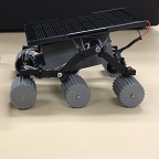
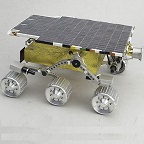
The Mini Pathfinder project for Spring 2017 is a scaled and modeled after NASA’s 1997 Sojourner rover of the Pathfinder mission. It will utilize the 3Dot board and a custom PCB. It is to be remotely operable with a fully functioning rocker bogie suspension system. It will be able to provide speed and battery telemetry to the user via the arxterra app and have a solar panel that charges the battery.
Mission Profile
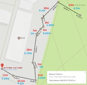
Our mission is a scaled version of the Pathfinder project. We will remotely traverse a course of 27.8 meters in length. The course will have 3 stairs it will descend and 3 stairs it will ascend with each stair being 27mm. During this course the Mini Pathfinder will demonstrate electronic differential turning, solar charging, proper rocker bogie mechanics and provide telemetry.
System Design
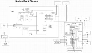
The Mini Pathfinder will use the 3Dot and a custom PCB for the extra motors and the encoders.
Subsystem Design
Modeling Results
Interface Definitions
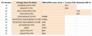
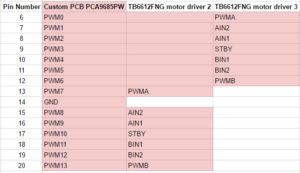
We have three interface definitions for three different IC’s. The first is for the 3Dot board. The next two are for the custom PCB that will have the two extra motor drivers and the digital io expander for the rotary encoders.
Cable Tree
Our cables will be routed from the motors and encoders through the suspension and into the electronics box. The solar panel will have a mount with a hole where the cable will connect so that it can charge the battery.
Mission Command and Control
Electronics Design
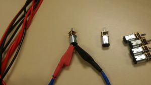
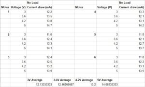
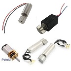
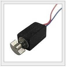
After the trade off studies, we have decided on micro metal gear motors and hall effect sensor based rotary encoders. To control the extra motors not connected directly to the 3Dot, we will be using a custom PCB that is base on the adafruit motorshield which houses a PCA9685 and two TB6612FNG motor drivers. In addition to the motorshield, we will also implement a MCP2301 I/O expander to take the digital input from the rotary encoders. The power for the extra motors will be supplied from the battery boost on the back of the 3Dot board so that we can access the same voltage that is supplied to the motors on board the 3Dot.
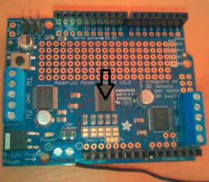
Figure 8. Adafruit Motorshield (PCA9685)
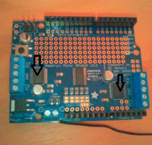
Figure 9. Adafruit Motorshield (TB6612FNG)
Firmware
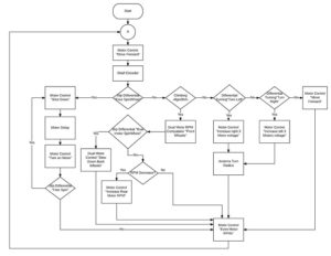
After discussing our project flow chart with an fellow Electronics and Control Engineer, Forest Nutter, we decided to redesign our flow chart. The initial image is the beginning stages of an overall view of the project.
PCB Schematic
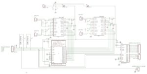
Since the 3DoT only has a single motor driver chip that is capable of driving two motors, we needed to make a custom PCB to interface with the 3DoT that will allow for 4 additional motors and also be able to take digital input for the rotary encoders. We modeled the motor driver off of the adafruit motor shield version 2.3. The motor shield consisted of the PCA9685pw PWM driver and two TB6612FNG dual motor drivers, which is what the 3DoT uses. The PCA9685pw allows for control of PWM outputs through the I2C bus, which is available through the 3DoT, so that we could properly control the motor drivers. For the digital IO expander, we chose the MCP23017 due to it having 16 digital IO channels for our rotary encoders, which use two digital outputs per wheel for a total of 12 outputs.
Our first schematic design had many errors that were easy to point out and a few that were only seen if looking very close. Fabian, previous EE 400D student, pointed out the schematic flaws and gave recommendations. One of the mistakes I made was in forgetting the pull up resistors for the I2C communication. The I2C needs the pull up resistors because most of the devices are active low. Throughout my ICs and the voltage in, (VCC and VBoost), I forgot to place decoupling capacitors for circuit protection and for clean signals. My first completed schematic looked great with labels on the wires. By simply clicking the name of the wire and looking closely, I connected the TB6612FNG dual motor driver outputs to each other which caused them to short. My project manager, Jon Her, advised that we start from scratch. After the irritative process the above image is the finish schematic. It was a tough process, but having the schematic looked over and over ensured that we have a potential working PCB.
PCB Layout
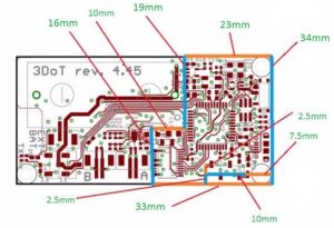
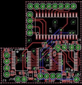
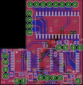
After the electronics and controls engineer(ENC), was finished with the schematic on EagleCAD, it was suggested that we try to make a printed circuit board(PCB) out of it and mount the PCB onto the 3DoT board like a “shield” because it was a level 2 requirement(See Figure 1). On the EagleCAD, requirements for the power lines had the size of 16mil. Data routes had 10mil. And there was a 20 drill size for vias. All of the lines had a 45 degree turn so that it doesn’t lose its connection when it is printed and powered up. The top and bottom planes of our PCB are ground copper poured planes. After placing all of the parts on the specified size of the layout, we made sure we used the DRC several times to make sure it completed all the requirements. We also ordered the parts and components before the PCB was made, so that it would arrive in a timely manner.
Dimension on 3dot board
Completed PCB Design
We created a custom PCB for our 3Dot board(see figure 3). After we did a final DRC on our final PCB, we then sent it to the president, customer, and Fabian for approval. We had to revise our board several times before it was approved, but once it was, it was sent to 4PCB to be manufactured. We then purchased the stencil from OshStecil. The next steps are to use the stencil and put solder paste on the top layer of the custom PCB. Then we will put the parts and components in its respective places. After, we will heat the board up using a heat gun so that the components will attach onto the board.
Hardware Design
Chassis
To ensure that the 3Dot sat correctly into the chassis, small cutouts were made to allow the Bluetooth module room along with a few pins that were sticking out from the battery holder. A channel was also cut out to allow a wire to access the battery boost on the underside of the 3Dot. There were also channels cut out to allow access to the usb port and the power switch on the 3Dot.
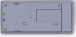
Figure 15. Inside the chassis
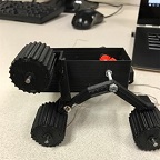
To allow proper rocker bogie mechanics, a three beveled gearbox was utilized. Each gear has 16 teeth to allow for a 1:1 gear ratio from the left side of the suspension to the right side.
Solar
As a requirement, the Mini Pathfinder was to have a Solar Panel charge the battery on the 3dot board. To accomplish this, the solar panel needed to be scaled to the rover, while also being able to supply enough voltage and current. The solar cells also needed to be encapsulated. The model of the solar panel was closely modeled after the Sojourner Rover.
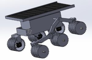
Figure 17. Solar Cell on the Mini Pathfinder
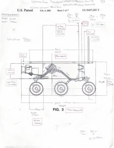
With the help of the chassis manufacturer for the mini pathfinder, we were able to scale the size in which the solar panel needed to be. The model was scaled using schematic renderings of the real Sojourner that were found on the internet. The size of the solar cell needed to be around 122x52mm.
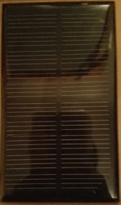
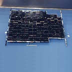
Once the size of the panel was found, I needed to find solar cells that were able to charge the 3dot battery and that would fit that size and then encapsulate them. To meet this, I used a 5V 200mA already encapsulated cell that was bought in store. The size of the solar cell was 120x70mm, which fit the requirement of size.
A micro usb was attached to both the positive and negative leads of the solar panel.
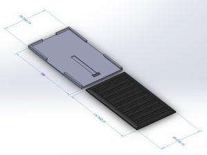
After finding the type of solar cell I’d be using, a way of holding the cell onto the rover needed to be found. Using Solidworks, I was able to create a holder to house the cell in place with a hole in the bottom to allow for the micro usb plug to pass through to connect to the 3dot board through the outside. This holder allowed for easy replacement of the cell, if needed. The cell could easily be removed by sliding in and out.
In conclusion, the solar cell needed to be tested more in order to observe how long it really took to charge the battery. Overall the solar cell was a success in looks and functionality as far as charging.
Verification & Validation Test
Verification and validation can be viewed at this link.
https://drive.google.com/open?id=1D4-kNlP_zy35XqHd-88Zd2Wl2X3w6gr05WJnChsNDzU
Project Status
Power Allocation
Mass Allocation
3d Print Allocation
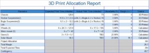
Figure 23. 3d Print time allocation
Cost Report
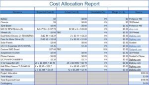
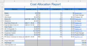
While we were able to get many parts and pieces for free, what cost the most was the custom PCB parts and the rotary encoders.
Burndown and Percent Complete
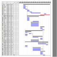
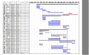
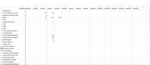
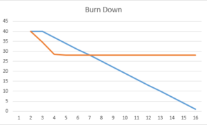
With all our tasks still left to finish and the progress we made on the project. We finished at %62 completion and remained behind schedule.
Concluding Thoughts
If there is anything I would change knowing what I know now, it would to ensure that progress is made consistently every week and that the project schedule be updated at every opportunity. Meeting up with Professor Hill is always a good idea as well. He has valuable input, and tries to help. The lectures may not cover everything but that is why there is so much documentation on Professor Hill’s website. I would also suggest reading over all the material and not taking any other classes that require a lot of time, as this class will already eat up all your time.
Project Resources
Project Video: https://youtu.be/HVbv6seOrCA
CDR:https://drive.google.com/open?id=1jm68b_I-lYIxEX2KnLQ9umSzJKdmA3KJs0HE2ciRDsY
PDR:https://drive.google.com/open?id=1ROLFfi2FNQnKXeBWZFecfNi36JnrB8bCFhlLQb2EYzE
Project Libre:https://drive.google.com/open?id=0BwLPwnTqIptrcWEwalpwLS1oVzA
Burndown:https://drive.google.com/open?id=0BwLPwnTqIptrWHE0c3lnbHEtYnM
Verification and Validation:https://drive.google.com/open?id=1D4-kNlP_zy35XqHd-88Zd2Wl2X3w6gr05WJnChsNDzU
Solidworks:https://drive.google.com/open?id=0BwLPwnTqIptremdfTTRaNkY5bFE
Fritzing Files: https://drive.google.com/open?id=0BwLPwnTqIptrc2xkWm5tYVdiM0U
EagleCAD:https://drive.google.com/open?id=0BwLPwnTqIptrM1pZbllodXVnbnM
Arduino Firmware: https://drive.google.com/open?id=0BwLPwnTqIptrQldiNFI1cDg3cW8

