
Color Test Blog Post
By: Alan Valles (Electronics and Control)
Approved by: Ijya Karki (Project Manager)
Table of Contents
The purpose of this experiment is to find the optimal distance between the phototransistor, TCS 34725 photo transistor, and the surface of the object to be read. This distance will allow us to create a cavity on the inside of the foot with the right depth to properly house our instrumentation.
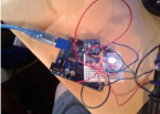
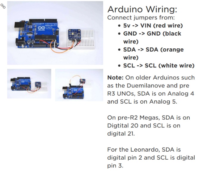
The Breadboard was set up as follows, and the guide that was followed was to set up per the adafruit directions found here:
https://learn.adafruit.com/adafruit-color-sensors/assembly-and-wiring
The Arduino Uno with an atmega328p was used as the microcontroller in this experiment. The sketch below prints the raw value of the color readings to the serial monitor.
First, a control reading was taken which grabbed the ambient color environment this value was found to be
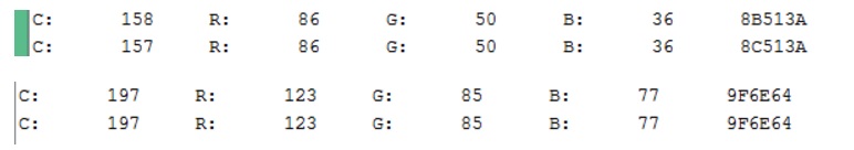
Here is also some of the raw data from the output the important data that was used in the readings was the RGB values in the columns.

After tabulating all of the raw data from the serial monitor and was put in the table below.
As shown in the table below, the delta between the green value for the control was greatest at ⅛ of an inch. However, Based on observation As the color cards were closer to the phototransistor, at a certain point the sensor did not greatly distinguish between Green and Blue Construction paper. However, this could be due to the fact that the colors used were not BOLD. Therefore, the correct materials should be used as the color sensors, such as dark construction paper. The ambient light environment the experiment was performed in may have also led to alter the results. Since an on board LED will provide the lighting source, no other ambient light is needed. Therefore, under optimal conditions the cavity in the foot will be closed and will not allow light in. However, even with external environmental light, the phototransistor will function to some degree.
| Card | Control | 2inches | 1inch | ¾ inch | ½ inch | ¼ inch | 1/8 inch |
| Red | 123 | 167 | 304 | 442 | 697 | 1712 | 7168 |
| Green | 85 | 145 | 342 | 542 | 944 | 2535 | 12658 |
| Blue | 77 | 114 | 248 | 380 | 644 | 1707 | 8312 |
As a cautionary measure, and for added flexibility the recommended distance between the phototransistor and the floor is ¼ inch. This gives us enough room adjust the distance inside the assembled foot as needed. It will also operate at this exact distance. Even though ⅛ of an inch gives us a higher delta between the control reading, the added flexibility and additional room by creating the cavity ¼ of an inch will allow us to have more options when assembling the final robot. Also, at ⅛ inch there seemed to be similar readings between green and blue construction paper. However, this could be because the color of the object used. This color differentiation problem could be mitigated when choosing final materials for the power up pad.
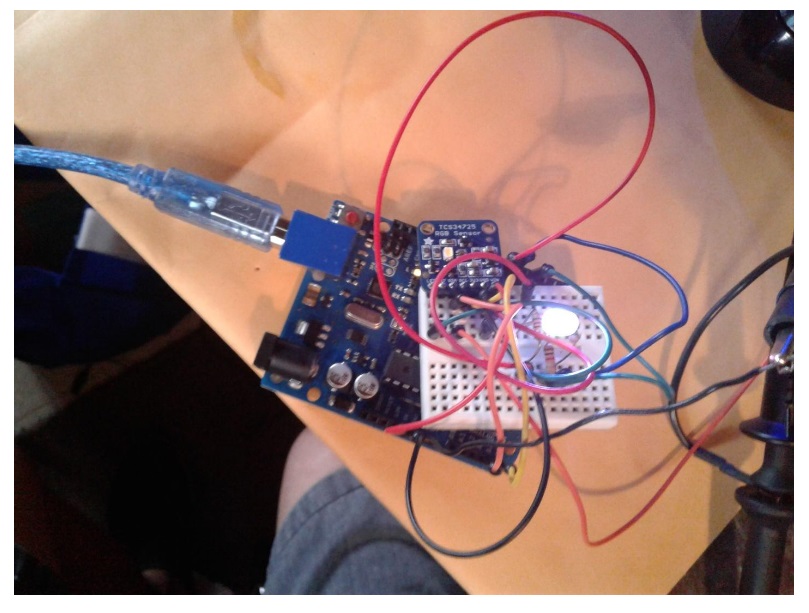
Figure 1: Realized Breadboard with RGB Matching LED
The LED is controlled using 3 digital pins from an Arduino Uno for this experiment. The functionality of controlling an indicator LED was also performed. During game play, the color will last for the duration of the power up length. This will be chosen at the discretion of the Game Committee and the Customer.
The code used was modified example code in the Adafruit_TCS34725 library.
#include <Wire.h>
#include “Adafruit_TCS34725.h”
// Pick analog outputs, for the UNO these three work well
// use ~560 ohm resistor between Red & Blue, ~1K for green (its brighter)
#define redpin 6
#define greenpin 3
#define bluepin 5
// for a common anode LED, connect the common pin to +5V
// for common cathode, connect the common to ground
// set to false if using a common cathode LED
#define commonAnode true
// our RGB -> eye-recognized gamma color
byte gammatable[256];
Adafruit_TCS34725 tcs = Adafruit_TCS34725(TCS34725_INTEGRATIONTIME_50MS, TCS34725_GAIN_4X);
void setup() {
Serial.begin(9600);
Serial.println(“Color View Test!”);
if (tcs.begin()) {
Serial.println(“Found sensor”);
} else {
Serial.println(“No TCS34725 found … check your connections”);
while (1); // halt!
}
// use these three pins to drive an LED
pinMode(redpin, OUTPUT);
pinMode(greenpin, OUTPUT);
pinMode(bluepin, OUTPUT);
// thanks PhilB for this gamma table!
// it helps convert RGB colors to what humans see
for (int i=0; i<256; i++) {
float x = i;
x /= 255;
x = pow(x, 2.5);
x *= 255;
if (commonAnode) {
gammatable[i] = 255 – x;
} else {
gammatable[i] = x;
}
//Serial.println(gammatable[i]);
}
}
void loop() {
uint16_t clear, red, green, blue;
tcs.setInterrupt(false); // turn on LED
delay(60); // takes 50ms to read
tcs.getRawData(&red, &green, &blue, &clear);
tcs.setInterrupt(true); // turn off LED
Serial.print(“C:\t”); Serial.print(clear);
Serial.print(“\tR:\t”); Serial.print(red);
Serial.print(“\tG:\t”); Serial.print(green);
Serial.print(“\tB:\t”); Serial.print(blue);
// Figure out some basic hex code for visualization
uint32_t sum = clear;
float r, g, b;
r = red; r /= sum;
g = green; g /= sum;
b = blue; b /= sum;
r *= 256; g *= 256; b *= 256;
Serial.print(“\t”);
Serial.print((int)r, HEX); Serial.print((int)g, HEX); Serial.print((int)b, HEX);
Serial.println();
delay(1500);// Added Delay in order to slow down serial monitor for reading.
//Serial.print((int)r ); Serial.print(” “); Serial.print((int)g);Serial.print(” “); Serial.println((int)b );
analogWrite(redpin, gammatable[(int)r]);
analogWrite(greenpin, gammatable[(int)g]);
analogWrite(bluepin, gammatable[(int)b]);
}
The distance range most optimal for the placement of the color sensor is between ¼ inch and ⅛ of an inch. However, in order to increase assembly flexibility and aid in final assembly the cavity containing the foot should have at least ¼ inch of separation between the sensor and the ground.
[1] https://learn.adafruit.com/adafruit-color-sensors/assembly-and-wiring
[2] https://learn.adafruit.com/adafruit-color-sensors/programming
Table of Contents
By: Brandon Perez (Missions, Systems, and Test Engineer)
Approved by: Ijya Karki (Project Manager)
Included is the post CDR updated requirements with an explanation of the quantitative values used.
Comment : The date is determined based off the class schedule and semester duration.
Comment : The budget has been determined by the customer.
Comment : These required items in our system have been set by the customer.
Comment : The speed has been determined based off the game arena dimensions, game duration, and the length of the typical expected path.
Comment : The turn angle interval has been set for the Biped to have effective turning capability when navigating the maze. The servos provided to us have mobility from 0 degrees to 180 degrees. If a turn command sets the Biped to turn at 180 degrees, then it will turn 180 degrees from where it is facing. This feature will help the Biped turn directly to the opposite direction to improve it’s agility in the game.
Comment : The distance has been determined since we expect to be sitting about 20ft away when operating the Biped during the game, “Save the Human”. The distance is yet to be determined by the game committee.
Comment : The mass has been determined by our Servo Axial Load experiment conducted by our Electronics and Controls engineer.
Comment : Colors have been selected because they are easily distinguishable from each other by the Human Vision System (HVS) when displayed on an RGB LED.
Comment : The minimum operating duration has been set by the customer.
Comment : The minimum incline and decline deviation level has been set by the customer.
Comment : The uneven surface height level has been set by The Game Committee.
Comment : This voltage rating for our DC Motor has been set because the 3Dot motor driver provides 5V. The torque rating has been set buy the minimum amount of torque required to move the legs.
Comment : The voltage rating for our servo has been because our External Power Supply with provide 5V. The torque requirement for the servo has been set by the minimum amount of torque required to shift the center-of-mass from foot to foot.
Comment : This requirement has been set so the MCU knows when our Bipeds legs have finished taking a step (half a revolution or 180 degrees) so it can stop the DC motor and shift the center-of-mass before taking the next step.
Comment : The servos being used at the feet of the Biped have been provided to us at no cost by the customer.
Comment : We have chosen a I2C compatible color sensor to be able to detect the color of the floor pads when walking over them.
Comment : We have chosen to use an IMU to sensor inclines an declines since it was provided to us at no cost by the customer.
Table of Contents
By: Brandon Perez (Missions, Systems, and Test Engineer)
Approved by: Ijya Karki (Project Manager)
Included is the post CDR updated system and software block diagrams.

This is Biped’s most up-to-date System Block Diagram. Start with the 3-Dot board block diagram provided in the 3-Dot folder.
On the bottom left, you can see the Arxterra App on the Android Mobile Device communicating with the Bluetooth v4.0 BLE Transceiver on the 3Dot Board.
On the top left, we have a 7.4V Li-Ion Battery connected to an LDO 5V Regulator which then connects to the external battery connector of the 3Dot board.
On the right side of the diagram you can see our DC Motor connected to Motor A pins of the 3Dot board. Servo (arms) and Servo (body) used for shifting center of mass are attached at the servo pins of the 3Dot board.
On the bottom right, we have three sensors (IMU, Color Sensor, and Rotary Sensor) connecting directly onto the I2C Peripheral Interface pins (PWR, GND, SCL, SDA) of the 3Dot board. We also have an I2C GPIO Expander connecting the I2C Peripheral Interface to help interface with our remaining devices: Left Ankle Servo, Right Ankle Servo, and RGB LED.
What did we change from our previous design?
Now using one motor to control the walking movement to closely resemble the Theo-Jansen walking mechanism. A rotary sensor is being used instead of the optical sensor for ease of implementation and programming.
What may be subject to change?
Servos being used to control the Center of mass shifting may be removed due to our mechanical design shifting the center of mass entirely with the help of our crankshaft turning the ankles. We may not need the body servo to shift the center of mass of the system when walking on inclines since we can mechanically design our system to be stable for varying angles. If that’s the case, we would be left with an RGB LED on the GPIO expander. However completely removing the servo to shift the center of mass is unlikely. A better solution would be to use both the mechanical design and a servo to shift the center of gravity (similar to the Theo-Jansen Biped).
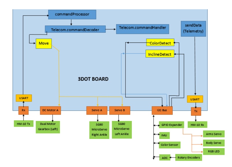
This is Biped’s most up-to-date System Software Block Diagram.
What has changed?
Our 2nd DC Motor has been taken out so our software has now changed. We are possibly not going to add any custom commands since we can ultimately utilize the parameters from sent to the predefined Move command and modify them to control our DC motor, and our 2 servos used for turning. The this will work is explained in the Arxterra Control Panel Blog post.

Table of Contents
By: Brandon Perez (Missions, Systems, and Test Engineer)
Approved by: Ijya Karki (Project Manager)
The predefined move command in Arxterra Control Panel located at address 0x01 operates under parameters set by the Directional Buttons (D-PAD) widget which is already on the control panel by default.
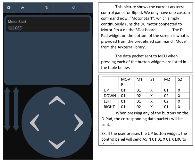
How we will use these data packet values to our advantage?
Since our MCU receives [A5 N 01 01 X 01 X LRC]. If the data transmission is successful, then we are only concerned with the highlighted values in the data packet [A5 N 01 01 X 01 X LRC]. The first value in the highlighted part of the data packet is the address of the predefined or custom command. In the data packet, 01 01 X 01 X, the green highlighted part of the code “01” is the command address. The following blue highlighted part of the data packet, “01 X 01 X”, are the parameters. Our goal to operate our Biped is to utilize these parameters to effectively have our Biped walk forward, turn left, and turn right. We will have to modify the code in the move command to include control of servos to have our Biped turn and walk without the use of any custom commands.


By: Brandon Perez (Missions, Systems, and Test Engineer)
Approved by: Ijya Karki (Project Manager)
Table of Contents
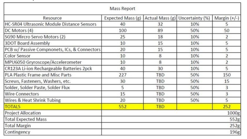

Changes to Mass Report:
New mass report is more organized and more easily read. Lots of items were bundled into the miscellaneous section. Ultrasonic sensors were taken out. All known masses were inputted and unknown masses were left as “TBD”. Allocation was determined by the mass our servos on the ankles could handle to turn.


Changes to Power Report:
2 DC Motors are now being used and ultrasonic sensors were ultimately removed off the system. A new battery was selected to be used, therefore we updated our Power Allocation to power that our new battery could provide over the course of an hour. Printed Circuit board was taken off since it practically consumes very minuscule power compared to the rest of the system. All components “Actual Power Consumption” has been left as “TBD” since our system hasn’t been constructed all together yet.
By: Brandon Perez (Missions, Systems, and Test Engineer)
Approved by: Ijya Karki (Project Manager)
Table of Contents
September 4th, 2016
Level 1
1.Shall be finished by the 9th of December, 2016 as designed in the CSULB calendar to correspond with the duration of the EE 400D class.
http://web.csulb.edu/~hill/ee400d/F’16%20Syllabus.pdf
2.Shall use a 3Dot board embedded system.
http://web.csulb.edu/~hill/ee400d/F’16%20Project%20Objectives%20and%20Mission%20Profile.pdf
3.Shall use one custom SMD I2C shield.
http://web.csulb.edu/~hill/ee400d/F’16%20Project%20Objectives%20and%20Mission%20Profile.pdf
4.The BiPed shall participate in an end of semester (December 9th, 2016) game where the BiPed’s goal is to outrun Velociraptor out of the arena with Goliath serving as its “eyes.”
http://web.csulb.edu/~hill/ee400d/F’16%20Project%20Objectives%20and%20Mission%20Profile.pdf
5.The BiPed shall use two DC motors to control walking movement of two legs. The choice of the DC motor will be compatible with the 3DOT board.
6.The BiPed shall walk statically and should demonstrate dynamic walking over flat, inclined, and declined surfaces for the entire duration of the game without falling over.
7.“Control of the walking robots will use the Arxterra Android or iPhone application operating in RC mode”
http://web.csulb.edu/~hill/ee400d/F’16%20Project%20Objectives%20and%20Mission%20Profile.pdf
8.The BiPed should be able to turn left and right at a maximum of 90 degrees at a time.
9.The BiPed should be able to maneuver around the arena and should avoid collisions with surrounding objects.
Level 2
1.Should use four ultrasonic sensors to support the BiPed in preventing numerous collisions into surrounding objects. Refer to requirement 9, level
2.BiPed will have a Bluetooth v 4 .0 BLE Transceiver integrated circuit that will be able to communicate with the class website of Arxterra. Refer to requirement 7, level 1
3.The 3Dot board shall be powered by a single CR123A 3.7V 650mA rechargeable Li-ion battery. A 9V battery will be used to amplify the 3Dot board’s signals. Refer to requirement 2 and 4, level 1.
4.The motors will receive their required voltage under operating conditions, as specified above, from the CR123A battery and the 9V battery.
5.The BiPed will use 2 DC motor to control its main walking motion. Refer to requirement 5, level 1.
6.The BiPed should use one wheel attached to one motor on each foot to execute the left and right turns. Refers to requirement 8, level
7.The I2C shield will utilize 4-pin connectors as well as a four-pin cable assembly to connect the four ultrasonic sensors via the I2C interface. Refer to requirement 3, level 1.
8.Biped should use a gyroscope as a sensor to determine its position with respect to the ground and shift center of mass in front of it or behind it when walking on inclined or declined surfaces respectively. The MPU-6050 (Gyroscope + accelerometer) should be used since it was implemented by previous BiPed projects and test software is readily available. Refer to requirement 6, level 1.
Oct. 10, 2016
Level 1 Requirements
1. Will be finished by the 9th of December, 2016 as designed in the CSULB calendar to correspond with the duration of the EE 400D class.
http://web.csulb.edu/~hill/ee400d/F’16%20Syllabus.pdf (Program Requirement)
Comment: Requirement left unchanged because it emphasizes a time-frame for our project.
2. Shall use 3Dot Board embedded system.
http://web.csulb.edu/~hill/ee400d/F’16%20Project%20Objectives%20and%20Mission%20Profile.pdf (Project Requirement)
Comment: Replaced word “one” to “a”. The previous requirement was forced to be quantitative.
3. Shall create a shield for the 3Dot board that utilize the I2C interference
http://web.csulb.edu/~hill/ee400d/F’16%20Project%20Objectives%20and%20Mission%20Profile.pdf (Project Requirement)
Comment: The new requirement is reworded for clarity.
4. Shall participate in an end of semester game where the Biped’s goal is to avoid contact with the Velociraptor. The Goliath team will be providing real-time video of the arena to the Biped group.
http://web.csulb.edu/~hill/ee400d/F’16%20Project%20Objectives%20and%20Mission%20Profile.pdf (Project Requirement)
Comment: Updated requirement provides a clearer description of the Mission Profile to the reader. Mission Profile needed to be restated in our requirements since it directly affects our overall system design.
5. Shall use a DC motor(s) to control its walking motion. (Project Requirement)
Comment: Removal of unnecessary information in the second sentence. The updated requirement emphasizes that each leg contains its own DC motor.
6. Shall be able to walk on flat, inclined, and declined surfaces of ± 6.5° angle measurement. (Level 2 Requirement)
Comment: Since the arena is described to be an environment with varying surface angles of ± 6.5° this requirement will now be serving as a Level 2 system requirement as a direct result of Level 1, Requirement 4.
7. “Control of the walking robots will use the Arxterra Android or Iphone application operating in RC mode”
http://web.csulb.edu/~hill/ee400d/F’16%20Project%20Objectives%20and%20Mission%20Profile.pdf (Project Requirement)
Comment: Requirement left unchanged since it is a project requirement from the customer for the teams to utilize the Arxterra Application for telemetry via Bluetooth to the 3Dot board.
8. The BiPed shall be able to turn left and right. (Level 2 Requirement)
Comment: The previous requirement stated a measurement of turning without any evaluation of why it had to be a maximum of 90° turns. This comment will now be utilized as a Level 2 system Requirement as a direct result of Level 1, Requirement 4.
9. This requirement will no longer be used. (Removed Requirement)
Comment: Removal of requirement because it is not a customer expectation or constraint.
10. Shall use a portable energy sources which should be capable of supplying power of a minimum duration of an hour. (Level 2 Requirement)
Comment: This requirement will be kept as a Level 1 Requirement since it emphasizes how long our system should be able to operate as a requested by the customer.
Level 2 Requirements
1. All sensors and actuators in our system shall be interfaced through the 3Dot board. Level 1, Req. 2
2. The 3Dot board only provides 2 DC motor drivers, and 2 servo drivers for direct component connection, therefore any sensors or additional actuators shall be controlled via an expandable 12C device addresser. Level 1, Req. 3
3. The Biped shall be walk, turn, detect pads on the floor, and operate for a minimum time frame of an hour in order to successfully compete in game designed by the game committee. The Goliath team shall require a proximity range from the Biped to provide video content for the Biped controller. The Arena in which the game will take place shall contain varying surface angles, therefore our Biped shall be able to walk on inclined and declined surfaces of ± 6.5°. Level 1, Req. 4
4. A DC Motor shall be allocated to control each leg to reduce the amount of torque applied if just one motor was being used. Level 1, Req. 5
5. Our Biped’s 3Dot board shall receive telemetry via Bluetooth communication with the Arxterra Application running on a group member’s Android device. Level 1, Req. 7
Oct. 16, 2016
Level 1 Requirements
The Biped Shall Statement:
1.Shall use a 3Dot Board embedded system.
2.Shall have a shield for the 3DOT board that will utilize the I2C interface.
3.Shall use DC motors to control its walking motion.
4.Shall be able to walk on inclines of (+/-) 6.5 degrees.
5.Shall be operated through Arxtrerra firmware via Bluetooth telemetry.
6.Shall be able to turn left and right.
7.Shall use a portable energy source capable of supplying power for an hour.
Level 2 Requirements
The Biped Shall Statement:
2.The system’s sensors and actuators shall interface through the 3Dot board. All system software shall be compiled onto the 3Dot board.
3.Arxterra firmware files shall be included in our software package for the 3Dot board.
4.An I2C interface shall be used to address additional devices for our system.
5.Two DC motors shall be used on our Biped to produce a walking motion.
6.Shall use a shaft encoding system to help keep the leg movement system in sync with the weight shifting system.
7.Servos on each of the Biped’s feet shall be implemented to produce turning.
8.Shall use a color sensor to detect floor pads in the playing arena.
9.Shall use a RGB LED to display the color of the pad that the color sensor has detected.
10.Shall use a servo to shift the system’s center of mass over from foot-to-foot.
11.Shall use accelerometer to detect when the Biped is on an incline or decline.
12.Shall use PID control method to keep the system balanced on inclines and declines.
13.Shall use a servo to shift the system’s center of mass when walking on inclined and declined surfaces.
Nov. 6, 2016
Program Requirements:
1. The Biped shall be ready to participate in the game, “Save The Human”, proposed by the game committee on December 14th, 2016.
2. The Biped budget determined by the customer shall not exceed $125.00.
Project Level 1 Requirements
The Biped Shall Statement:
1. Shall use a 3Dot Board embedded system.
2. Shall have a shield for the 3DOT board that will utilize the I2C interface.
3. Shall use one DC motor to control its walking motion.
4. Shall be able to walk on inclines of (+/-) 6.5 degrees.
5. Shall be operated through the Arxtrerra control panel via Bluetooth commands.
6. Shall be able to turn left and right when commanded.
7. Shall use a portable energy source capable of supplying power for an hour.
8. Shall be able to detect power-up zones that will be present during the game.
Project Level 2 Requirements
The Biped Shall Statement:
1. The Biped’s DC Motors and Servos shall have an operating voltage between 4.0 – 6.0V.
2. The Arxterra control panel shall be able send commands to the 3Dot and receive telemetry of the 3Dot board.
3. All external devices shall need to be 12C compatible or included onto an I2C GPIO expander.
4. Our choice of motor shall have a shaft output to both legs which shall be out-of-phase by 180°.
5. A rotary encoder shall be embedded onto the DC Motor shaft to provide data regarding the shaft’s position.
6. The servos acting as ankles on the Biped’s feet shall be able to turn the entire Biped’s mass of (TBD) while the Biped is standing on one foot. 7. Shall use a color sensor to detect color pads in the playing arena.
8. Shall use a RGB LED to display the color of the pad that the color sensor has detected.
9. Shall use a servo that produce a torque rating of at least (TBD) to raise the robot’s arms laterally.
10. Shall use accelerometer to measure the angle of incline the system is in when standing normal to the surface.
11. Shall use PID control method to keep the system balanced on inclines and declines.
12. Shall use a servo to correct the center of mass of the system when walking on inclined or declined surfaces.
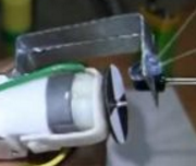
Table of Contents
By: Alan Valles (Electronics and Control Engineer)
Approved by: Ijya Karki (Project Manager)
A rotary encoder must be used to get the positional reading of the motor shaft. This information is key in understanding which part of the walk cycle the robot is in. For example, if the robot’s right foot is on a color pad, the rotary encoder would read that it is in this position.
With this information, the code could be utilized to read the color pad at this part in the flow chart. Another example is if we want to turn left, the walk function would be called until the left foot is planted. It is at this point that the robot would hold position, shift weight to the planted foot, and then use the ankle servos to turn.
Since a precise stepper motor will not be used in walking, a motor encoder must be used in order to have positional awareness of the robot. The two types of encoders that will be considered are an optical encoder and a rotary position sensor. The optical encoder subsystem uses a QRD1114 phototransistor and diode to send an IR signal and read with the phototransistor. It reads the amount of the IR signal that is reflected. The phototransistor receives an analog signal based on the light that is reflected and absorbed by the phototransistor. Thus, as the resolution of slices increases as shown in figure 4-17 or the parallax student manual, the resolution is improved. Another circuit is also necessary to convert the analog to a digital signal to be read by an input; the I2C bus is used. The other option is to utilize a rotary position sensor. This is essentially a potentiometer that is connected to the shaft so it is allowed to freely rotate. Its resistance is anywhere between 0 and 10k depending on the angle between o and 360 degrees. However, the Bourns 3322 series position sensor has a unknown region where its value is between 330 and 360 degrees based on the data sheet.
Table 1
| Encoder | MFG | Challenge | Additional components | Price: |
| Rotary | Bourns | Unknown region between 330 and 360 degrees | ADS1015 | 2.73 |
| Optical | TI | Signal processing and acquisition | OpAmp COmparator | 1.77 |

In Order to meet scheduling requirements, the rotary position sensor will be used in order to meet our deadline. It will also be used by the velociraptor group which will aid in debugging and coding. The best way to move the all projects forward across The Robot Company is to work in a collaborative environment which is easier if the platform is consistent across all BiPed robots.
An experiment was also done by the Electronics and control Division to test the optical encoder circuits which is similar to a lab done on campus for control systems.
The code below was done by Electronics and Control and is modified from sparkfun guide below.
The code:
/******************************************************************************
QRD1114_Proximity_Example.ino
Example sketch for SparkFun’s QRD1114 Reflectance Proximity Sensor
(https://www.sparkfun.com/products/246)
Jim Lindblom @ SparkFun Electronics
May 2, 2016
Connect a QRD1114, 330 resistor and 10k resistor as follows:
QRD1114 Pin ---- Arduino ---- Resistors
    1              A0      10k Pull-up to 5V
    2              GND
    3                      330 Resistor to 5V
    4              GND
As an object comes closer to the QRD1114, the voltage on A0 should go down.
Development environment specifics:
Arduino 1.6.7
******************************************************************************/
int QRD1114_PIN = A0; // Sensor output voltage
int LED = 13;
int x = 0;
int y = 1;
int z = 0;
void setup()
{
Serial.begin(9600);
pinMode(QRD1114_PIN, INPUT);
pinMode(LED,OUTPUT);
}
void loop()
{
// Read in the ADC and convert it to a voltage:
int proximityADC = analogRead(QRD1114_PIN);
if (proximityADC < 630){
digitalWrite(LED,HIGH);
z=x;
}
else {
digitalWrite(LED,LOW);
y=1;
}
if (y==1){
increment();
}
if (z!=x){
Serial.println(x);
}
// float proximityV = (float)proximityADC * 5.0 / 1023.0;
// Serial.println(proximityV);
// Serial.println(proximityADC);
delay(10);
}
void increment()
{
if (digitalRead(13)==HIGH){
z = x;
x = x + 1;
y=0;
}
else if (digitalRead(13)==LOW){
x=x;
y=1;
}
}

Figure 1

Figure 2
Figure 1 shows the realized circuit and an example of the Pizza slices that could be used for the encoder. Since it is difficult to get precise values from the optical sensor, the code above utilizes flags and a threshold value, which when passed dictates a state flag y. The circuit shown in figure 2 is a example circuit that could be used to output a square wave into an available pin on the GPIO expander, SX1509. However, due to the additional circuit complexity, and software hardware integration complexity, the rotary position sensor will be used since it is the most straight forward.
The Bourns 3382 series in conjunction with an ADS1015 delivers a digital value that is able to be mapped onto an SX1509 empty pin. The ADS1015 takes an additional address space on the I2C bus and appears much more straightforward. The optical sensor had to poll and use a counter to keep track of the number of logic HIGH that appeared. There are issues with timing based on this design among other things. Therefore, the Rotary encoder suite in conjunction with an ADS1015 will be used going forward.
In Conclusion a Rotary positions sensor, Bourns 3382 series will be used in conjunction with an ADS 1015. This subsystem was chosen over an optical encoder due to the simplicity, in hardware and software design.
[1]https://www.parallax.com/sites/default/files/downloads/122-28176-Process-Control-Text-v1.0.pdf
[2]https://www.sparkfun.com/datasheets/BOT/QRD1114.pdf
[3] https://learn.sparkfun.com/tutorials/qrd1114-optical-detector-hookup-guide
[4]http://www.digikey.com/catalog/en/partgroup/3382-series/7106
[5] http://www.ti.com.cn/cn/lit/ds/symlink/ads1015.pdf
[6] http://www.digikey.com/product-search/en?mpart=3382H-1-103&vendor=118
[7] http://www.digikey.com/product-detail/en/fairchild-semiconductor/QRD1114/QRD1114-ND/187536

Servo Ankle
By: Alan Valles (Electronics and Control Engineer)
Approved by: Ijya Karki (Project Manager)
Table of Contents
An unique design of Fall 2016 BiPed is the use of ankle servos. An experiment was done in order to see how much mass/weight can be held up on one ankle servos at a time. This is one of the primary constraints when selecting materials because the entire weight of the robot must be turned with the ankle servos.
All Servo motors have a stall torque which is the amount of torque that causes the servo to be fixed or not move.
Torque = Force * Lever arm and Force = mass*acceleration_due_to_gravity.(9.8m/s^2).
However, the ankle servos are slightly different than conventional servos because the entire weight of the robot is not hanging directly on the lever arm, but rather the force of the object due to gravity is parallel to the shaft of the servo. Under Ideal conditions, the Center of Mass would be Entirely over the shaft which would mean there is no torque. However, the test was done to see how much mass could be put directly on top of the servo.
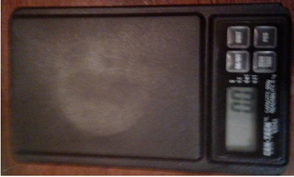
Figure 1
A Centech scale with a maximum reading of 500g was used for measure the weights of various objects. Ultimately, a coffee cup was used as the maximum weight of about 450g. However, the movement of the servo with the weight on top was not stable. 450g was the maximum mass achieved before the material was not stable directly on top of the servo. A plastic plate was fixed to the top of the servo in order to load the plate with various materials.
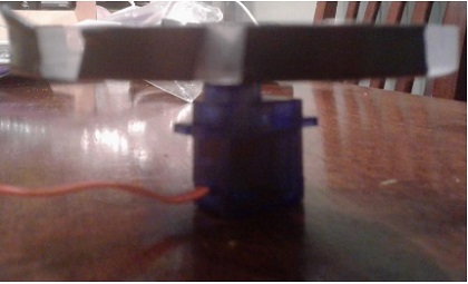
Figure 2
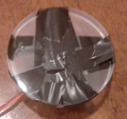
Figure 3

Figure 4


/* Sweep
by BARRAGAN <http://barraganstudio.com>
This example code is in the public domain.
modified 8 Nov 2013
by Scott Fitzgerald
http://www.arduino.cc/en/Tutorial/Sweep
*/
#include <Servo.h>
Servo myservo; // create servo object to control a servo
// twelve servo objects can be created on most boards
int pos = 0; // variable to store the servo position
void setup() {
myservo.attach(9); // attaches the servo on pin 9 to the servo object
}
void loop() {
for (pos = 0; pos <= 180; pos += 1) { // goes from 0 degrees to 180 degrees
// in steps of 1 degree
myservo.write(pos); // tell servo to go to position in variable ‘pos’
delay(15); // waits 15ms for the servo to reach the position
}
for (pos = 180; pos >= 0; pos -= 1) { // goes from 180 degrees to 0 degrees
myservo.write(pos); // tell servo to go to position in variable ‘pos’
delay(15); // waits 15ms for the servo to reach the position
}
}
The Arduino Servo.h library was used in conjunction with the test code above. However, the default delays were modified in order to slow down the motion for test mass stability. I improved the process by using other smaller masses that are more compact and easier to load and balance onto the test plate. Visual inspection showed that the servo motor performed with no noticeable speed decrease even with nearly 500g on it. This was a surprising result and in the future more in depth study will be done to load it past the maximum scale reading of 500g.
In conclusion, various masses were loaded onto the top of a servo. The maximum mass on affixed on top of the servo was 450g. However, based on visual inspection and more mass can be attached as long as it is stable.