Fall 2015 MicroBiPed Verification and Validation Tests

VERIFICATIONS & VALIDATIONS REQUIREMENTS

By Railly Mateo (Systems Engineer)
Approved by Paul Oo (Project Manager)
Approved by Railly Mateo (Systems Engineer)

Here is the link to the full Test Plans for Verification and Validation.

Fall 2015 MicroBiPed PCB

PCB DESIGN

By Michael Balagtas (Manufacturing Engineer)
Approved by Paul Oo (Project Manager)
Approved by Railly Mateo (Systems Engineer)

Introduction:

The Final PCB layout is the responsibility of the Manufacturing engineer. To maximize the grade acquired for the assignment, a combination of through hole and SMD packages were utilized in the design.

Obstacles:

The problem presents itself when there are too many components on a board. Some components will have plenty of connections, sometimes to the point where there is no choice but to block other channels. Naturally, the solution to this would be to rotate the device. However, doing so can block even more channels. Another option is to create a double sided junctions. However, the double sided wires starts blocking other bottom sided channels utilized by other components. The only other option would be to go around it. Unfortunately, the free version of EAGLE has a limit of 2 in. x 2 ½ in; therefore, we do not have the liberty of space to maneuver around the conflicted part.

pcb

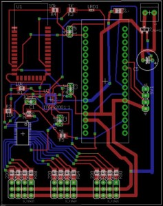
Final PCB Design. Note the part with the array of blue wires connected at the bottom left. That part is the servo driver, currently in the bottom of the board. Without it on the bottom, the order of the servo pins on the bottom would be convoluted.

The image above shows our finalized design for BiRex’s PCB. The red lines represent the copper tracing on top of the board, while the blue lines are underneath. An unpopular but effective method would be to have double sided SMD’s. By having an SMD on the bottom side, it is essentially mirrored by the axis that it is flipped on. This allows for some flexibility for routing.

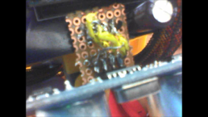
There were some unforseen problems, however. When the board was mounted on the robot, all of the parts were nominal except for the ultrasonic pins, which are the 4 pins on the right of the picture. The pins were oriented in such a way that the ultrasonic was facing backwards; we needed to mirror the pins somehow. We used a daughter board to jury rig the pins into flipping to correct the mistake, which is the brownish board in the following picture.

daughterboard

Conclusion:

In summary, if the design needs a mirror, a double sided PCB can be utilized. However, it is important to note that it can limit the mounting capabilities. Furthermore, when using Eagle, having a reliable mouse aids in alleviating the amount of controls needed to design.


Fall 2015 MicroBiPed Center of Mass

WORST CASE SCENARIOS FOR CENTER OF MASS TESTING

By Michael Balagtas (Manufacturing Engineer)
Approved by Paul Oo (Project Manager)
Approved by Railly Mateo (Systems Engineer)

Introdcution:

Solidworks calculates the center of mass and the overall mass of the model based on the present stance of an assembly. While walking, it is important to have the center of mass as close to the most supported leg to maintain balance. Unfortunately, only Solidworks premium has the motion analysis option, which calculates the parameters while the model is in motion.

Method:

There is still an alternative to the center of mass study without the premium version, and that is with a worst case scenario test. That is, position the assembly in a manner where it is only supported by one foot, and the other is completely in the air. Naturally, there are two worst cases for a biped – one for the right leg and left leg worst case.

worst Right

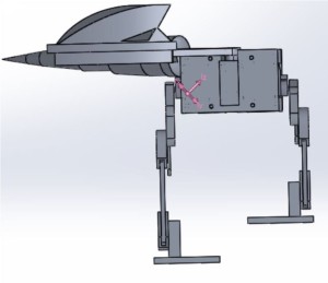
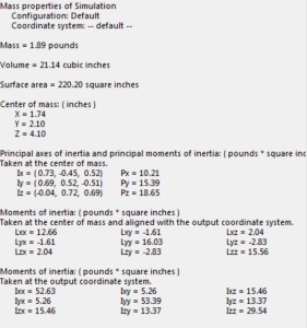
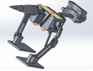
worst right calc Worst Case Scenario: Right Foot. The information on the bottom comes from the mass properties option in the Solidworks tools tab. Note the purple axis on the robot. That shows the center of mass on the robot, which is close to the joint, which is a good thing while walking.

The image above shows the worst case scenario test along with mass properties on BiRex. The goal is to have the pink axis as close to the leg as possible. When the pink axis arrows are at the leg (with the foot that is planted on the ground), then the BiRex is balanced. Other methods outside of the frame could be used for compensation.

Conclusion:

For the 2015 Biped team, this method helped validate the Level 2 requirement of maintaining balance while the robot is walking. This does not account for other unforeseen problems, but this test helped with validating one of our core requirements.

Fall 2015 MicroBiPed Stress Analysis

STRESS ANALYSIS USING SOLIDWORKS

By Michael Balagtas (Manufacturing Engineer)
Approved by Paul Oo (Project Manager)
Approved by Railly Mateo (Systems Engineer)

Introduction:

(This blog is written to accommodate stress test studies on strain heavy designs).

Previous Biped Robots had multiple joints connected by the servos. As such, it was easy to assume that, so long as the servo enclosure was thick and strong enough, the Biped could withstand the forces acted upon it during operation. However, for the 2015 BiRex design, the legs and joints are all connected via screws and nuts for articulation. Also, in order to reduce weight and size, some parts were thinned and holed, reducing their durability. This presents the team with a problem with the strain put on the joints and the parts as the BiRex moved.

Solidworks:

The parts had to be designed just enough to be easily manufactured and durable for walking. To accomplish this, the SimulationXpress feature on Solidworks was used to analyze the part for breaking points. The Simulation allows a user to determine which faces of the part will have a force applied into it (in the team’s case, the ankles) and which parts are stationary. It then allows the user to pick the specific type of material that the part is made out of, to determine the constants. By pressing run, the simulation starts calculating.

Results:

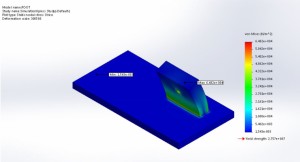
stress

The von Mises test results. Solidworks allows you to determine which faces are stationary and which ones have forces acted on them. The ankle, which is the thick block, has all of the forces, and the red coloration indicates where the most vulnerable area is.

As a gauge, we considered the maximum force given by the robot as F = ma, which is the mass times the gravitational constant. In our case, 1.438 x 9.8 = 14.09N. The report indicated that the maximum force is above 65000N, which is way above our total forces.

The simulation then compiles a report in Microsoft Word that shows the simulation parameters and results. The most important is the von Mises Stress, which determines the force at which a material deforms. By being below this, the part is guaranteed to retain state after operation.

Fall 2015 MicroBiPed Wiring Diagram

FINALIZED WIRING DIAGRAM

By Paul Oo (Project Manager)
Approved by Paul Oo (Project Manager)
Approved by Railly Mateo (Systems Engineer)

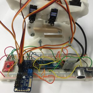
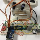
IMG_1746

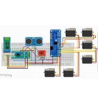
Breadboard Wiring Diagram

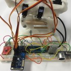
The image above shows the system integrated (without the battery) and connected to the 3rd generation of the BiRex prototype. To reduce the wiring of the main electronics system, we designed our own PCB on EagleCAD.

(Picture of PCB)

The image above shows the custom PCB for our BiRex. The details for how we designed in can be found on our PCB blog post. As previously mentioned, the production of a PCB reduces the complexity of wiring and creates a aesthetically pleasing look.

ssPgNDIWtiMxW7O

Wiring Method

Considering this year’s Project Objective is a feasibility demonstration, the overall aesthetic design is not a high priority.  In the image above, the yellow board represents the PCB, the wires represent the servo connectors, and the black cylinders represent wire looms. What is not seen is the battery (will be placed underneath the body), and the ultrasonic sensor (placed in front of the battery).

Conclusion:
As this project continues to progress into different Mission Profiles and Project Objectives, future generations can rely on the design innovations to understand how these changes affect the overall objectives. For example, the year’s model could potentially conceal the PCB by covering the back of BiRex with a 3D backbone print. The analog sensors (gyroscope and ultrasonic sensor) are limited to only be placed on the body (the neck, tail, and legs are mobile).


Fall 2015 MicroBiped Motion Sensor

MOTION SENSOR TRADE-OFF STUDIES

By Railly Mateo (Manufacturing Engineer)
Approved by Paul Oo (Project Manager)
Approved by Railly Mateo (Systems Engineer)

Parameters Gyroscope (ITG 3200) Accelerometer (ADXL335)
Input Voltage 3.3 3.3
Acceleration 10,000G 10,000G
Operating Temp Range -40 TO +105 CELSIUS -55 TO +125 CELSIUS
Storage Temp Range -40 TO +125 CELSIUS -65 TO +150
Price 16 to 20 dollars 14 to 28 dollars
Dimensions 3.0×3.0×0.9mm 4 mm × 4 mm × 1.45 mm

Overview:

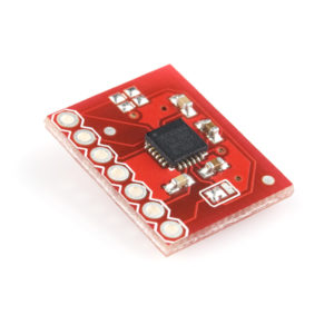
itg3200

ITG-3200

The accelerometer above is a compact device designed to measure non-gravitational acceleration. When the object it’s integrated into goes from a standstill to any velocity, the accelerometer is designed to respond to the vibrations associated with such movement.

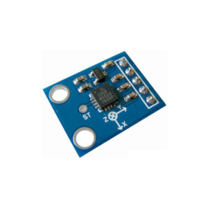
229-a-adxl335-triple-axis-accelerameter-analog-output-600x600

ADXL335

A gyroscope above is a device that uses Earth’s gravity to help determine orientation. Its design consists of a freely-rotating disk called a rotor, mounted onto a spinning axis in the center of a larger and more stable. As the axis turns, the rotor remains stationary to indicate the central gravitational pull, and thus which way is down.

Trade-Offs:

The table above gives specification comparisons between a gyroscope (ITG-3200) and an accelerometer (ADXL335).

Conclusion:

For our robot we were planning on using a gyroscope to measure the level of an incline on which our robot maybe standing on. However, the gyroscope only measures the change in the surface and then it stabilize itself. For example, if the gyroscope goes from flat surface to an incline, it will detect the differences in ground and then it will set this ground as its new flat ground. In the other hand, if an accelerometer goes from flat to incline, it will display the change in surface and maintain the angle of inclination. Therefore, an accelerometer should be used instead of a gyroscope.

Fall 2015 MicroBiPed Arxterra Application

ARXTERRA APPLICAIONT & ARDUINO IDE

By Railly Mateo (Systems Engineer)
Approved by Paul Oo (Project Manager)
Approved by Railly Mateo (Systems Engineer)

Configuration:

To establish communication between the robot and the phone, its important to know how the Arxterra application works and what kind of information it will send to the microcontroller (Arduino Micro). To interpret what the various telemetry commands were: the Bluetooth device (HC-06) was connected to the Arduino Micro. Next, the arxrobot-firmware was uploaded into the Arduino Micro to establish communication between itself and the Arxterra application (Android version).

Testing Connectivity:

To test connectivity, begin by opening he serial monitor on the Arduino. Play around by pressing on the Arxterra application. When the phone is not connected to the Bluetooth, the monitor will display “emergency exception 0x0100”. When the phone is connected, it will display “robber received command: 11”. When pressing on a direction (forward), five data inputs will be displayed on the monitor. According Hill’s command PDF file, the Arxterra application sends a 7 element matrix to the microcontroller.

Data Interpretation:

Data [0] A5 = Command Packet ID
Data [1] 05 = Packet Length N w/o parity byte
Data [2] 01 = Move ID
Data [3] 01 = Left Motor Forward
Data [4] 80 = Half Speed (128/255)
Data [5] 01 = Right Motor Forward
Data [6] 80 = Half Speed (128/255)
Data [7] A1 = Longitudinal Redundancy Check (LRC)

For our robot, the only elements of interest are data [2], data [3], and data [5]. This is due to our project only using servos, in comparison to using servos and motors. Thus the speed of the robot will only be controlled by using delays in the walking code.

Data [2]: if the command bit is 1, that tells the command decoder to issue a move command.
Data [3] and [5]: These elements are direction bits. If both are set to 1, it is interpreted as forward direction (would mean the reverse direction). However, our servos don’t go in reverse, therefore we won’t be setting these elements to 2.

Setting Up Walking Code:

Begin by pressing on the arrow control panel. Then write down all the telemetry responses that would be needed. By playing with remote functions, you will notice that setting data[3] and [5] to 1 and 1 will be move forward, 1 and 2 will be move to the right, and 2 and 1 will be move to the left.

Walking Command Examples:

If (data3 == 1 && data 5 == 1), the Arduino will read a series of servos angle that will make the walking forward motion.
If ((data3 == 1 && data5 = 2)), the Arduino will read a series of servos angle that will make the right turn.
If ((data3 = 2 && data5 == 1)), the Arduino will read a series of servos angle that will make the left turn.

You can see the implementation of the code in the Prototype blog post.

Fall 2015 MicroBiPed Prototypes

PROTOTPYE MILESTONES

By Railly Mateo (Systems Engineer)
Approved by Paul Oo (Project Manager)
Approved by Railly Mateo (Systems Engineer)

The video above shows the first step taken to understand the mechanics for how our Bipedal robot would walk. This model is considered our 1st Generation (1.0) of BiRex. It is a simply demonstration of a 5-axis leg using MG90S servos to rotate 2 axis, which then cause the rest of the leg to be displaced based on the angles of rotation. The commands used for this demonstration can be found in the Arxterra Application blog post.

This second video shows how we attempted to understand the coding for making our Bipedal robot walk. This model is considered our 2nd Generation (2.0) of BiRex. Although it has integrated 2 5-axis legs onto a body (wooden plank), this model lacked the feet needed to test stability.

This third video shows how we attempted to understand the motion for making our Bipedal robot walk. This model is considered our further developed 2nd Generation (2.5) of BiRex. As you can see, it has difficulty walking. This lack of balance comes from the fact that our legs cannot support overall stability alone, thus verifying the need to add the head and tail.

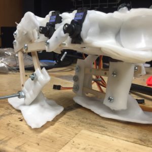
IMG_1852(1)

Image 1

The image above shows the inclusion of servos for head and tail. However, after showing the progress of our prototype to Professor Hill, he recognized the need to change the design of the leg. This model was unable to lift its leg up, but rather slid to go forward. Because of this detail, we were able to implement a more realistic prototype and find valuable feasibility information.

IMG_1853

Image 2 – 3rd Generation of BiRex

The image above shows the finalized design before moving into producing our last model. Although the plastic molding made the structure too heavy to stay standing, the legs’ rotations resembled human-like walking motion.

Conclusion:
After changing the Mission Profile & Project Objective, we were able to focus our time into learning from trials and errors. This, along with a progressive design innovation, gave us enough data to create proper verification and validation tests.


Fall 2015 MicroBiped Interface Matrix Update

FINALIZED INTERFACE MATRIX & DEFINTIONS

By Railly Mateo (Systems Engineer)
Approved by Paul Oo (Project Manager)
Approved by Railly Mateo (Systems Engineer)

SzTI3jcuUVDzZkg

Table 1

Table 1 above show the 1st portion of project’s updated system interface definitions. The left side of the table has information on our subsystem components, while the right side is simply the microcontroller (Arduino Micro). Each component is then defined by its pinout data (pin number and pin symbol), which is then used as information for the microcontroller’s pinout.

7vtOa7MLNMDapYW

Table 2

Table 2 above show the 2nd portion of project’s updated system interface definitions. Unlike the first table, this section focuses only on our servo interface. The left side of the table has information on the servo driver, while the right side is simply 6 µservos. Because the servo driver has no numbered pins, the table separates each section of the servo driver by its basic connections (PWM, V+, & GND). The µservos are then connected to these connections through their PWM, V+, & GND wires.

A full system block diagram explains how these subsystems structurally connect.
The wiring diagram post explains how we planned to eliminate any possibility of branch-like wiring.


Fall 2015 MicroBiPed System Block Diagram Update

FINALIZED SYSTEM BLOCK DIAGRAM

By Railly Mateo (Systems Engineer)
Approved by Paul Oo (Project Manager)
Approved by Railly Mateo (Systems Engineer)

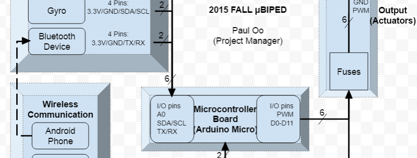
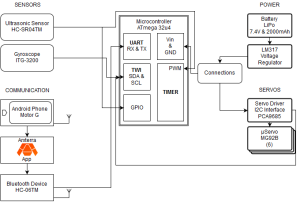
block diagram(1)

The block diagram above shows the updated block diagram for BiRex. The blocks are positioned based on their subsystem information. This post will give brief descriptions to explain each section of the block diagram.

The top left section comprises of two analog (orientation & distance) sensors. The ultrasonic sensor (HC-SR04) connects to the microcontroller (Arduino Micro) through the PWM & GPIO pins. The gyroscope (ITG-3200) connects the Arduino through its data line (SDA) and clock line (SCL).

The bottom left section comprises of 2 hardware devices (Bluetooth device & Android smartphone) for wireless communication between the Arxterra app and the microcontroller. The bluetooth device (HC-06) connects to the microcontroller through UART pins (RX & TX).

The top right section comprises of components (battery and voltage regulator) for energizing the system. The LiPo battery connects to the voltage regulator to ensure that we do not overload our subsystems. The voltage regulator (LM317) then uses our connections that bridge to the Vin and GND pins on the microcontroller.

Finally the bottom right section mechanical components (servos & servo driver). The servo driver (I2C interface) has two inputs and six outputs. It is energized from the battery and gets commands from the microcontroller through its data and clock lines. Then the signal is outputted to the six µservos (MG92B) allowing BiRex to walk.