By Kevin Huynh, Project Manager / Computer Systems and Software
Objective:
This blog will focus on the ideas behind how the code from projectbiped and the code from Spring 2014 handle the animation playback for walking and turning. It will also go into the reason for the switch.
ProjectBiped Code :
The most recent code can be found here:
http://www.projectbiped.com/prototypes/rofi/programs/arduino-action-playback
The code on project biped uses a timing system for the playback of the robot’s walking animation. The Action class holds all of the code for this movement method.
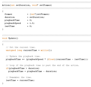
The timing system starts with the function Update, which calculates playbackTime with the variables currentTime, lastTime, playbackSpeed, and duration. The currentTime variable is determined by the Arduino command millis() which returns the number of milliseconds since the microcontroller began running the program. The lastTime variable is equal to the previous currentTime value from the last time the walking animation frame was updated.
The playbackSpeed is determined by the user, based on the speed they chose when creating action frames with in RobotPoser. The calculation value is assigned to a variable called playbackTime, which is used in the function GetCurrentFrame to get the frame the robot should be on. If the calculation for playbackTime resulted in a value greater than the duration, the duration value is subtracted from the playbackTime, to create the animation loop.

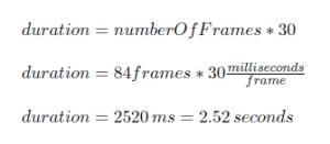
In the most recent code, the duration of the action is determined by the numberOfFrames variable multiplied by 30, but in the code exported from RobotPoser, it is multiplied by 20. ~I’m not exactly sure what those numbers are, but they are likely values for milliseconds per frame. This would result in a time value. For the most recent code, the duration would be 2.52 seconds for the entire walking animation.

Once playbackTime and duration are calculated, they are used in the GetCurrentFrame function. The parameter passed into GetCurrentFrame is a blank 1×12 array for containing the animation frame the robot will move to. The pointer sourceFrame points to the address of the frames array plus a value based on the playbackTime and numberOfJoints. From that address, the frame array takes 12 (numberOfJoints) from the frames array and the robot is told to move the servos to the specified positions.
Example:
When the robot starts up, the there is lastTime is set to 0. Suppose the value retrieved from the millis() command is 1000 ms, so currentTime = 1000 ms. The playback time is then equal to 1000 ms. Since the playbackTime is less than the duration of 2520 ms, there is no subtraction.
Then the GetCurrentFrame function is called and an empty 1×12 array named frame is passed into the function. From the equation, sourceFrame is equal to the address of the frames array + ((int)1000/30)*12. Since 1000/30 is type-casted to an integer type, the value is rounded down to 33, so sourceFrame = (address of the frames array) + 396. This points to the address of the first value of the 33th (if the first row is counted as the 0th row) frame of animation. Afterward, there is a for loop that loops 12 times to get all 12 values of the 33th row to put into the frame array for use in the SetServoPositions function. The frame array at 1 second should be:
{382, 70, -2837, 420, 4275, 1102, -1770, -472, 972, 0, -1520, -2612 }
Spring 2014 Code:
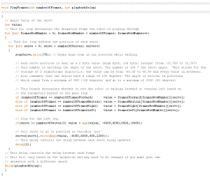
The code used for Spring 2014 used a simpler method for playing the action frames. Rather than use a timing system to determine which frame the robot should be on, the new code uses two loops to run through every element of the action frame array. One loop runs through the elements of each row to update each servo. The second loop moves from row to row to progress the animation. A playbackDelay variable is used to determine the speed of the action progression. The action of moving the servos to their positions is based on the SetServoPositions function from the original code. The rest of the code is similar to the original code.
Reason for the switch:
When creating the animations and testing them out on RobotPoser, there were no significant issues with the playback. However, when attempting to have the microcontroller handle the animation in a standalone code, the robot would start on a frame in the middle of the walking animation, rather than start on the first frame.
This issue became more prominent as more code was added to handle the obstacle avoidance using the ultrasonic sensor, since the delays caused by the use of the ultrasonic sensor affected the timing of the animation. The problem was found when two things happened. The first was that the incorrect leg oved forward at the start of the playback. The second was the effect of the addition of the ultrasonic sensor code and the right turn code on the forward walk layback. After the robot turned right in response to an object 30 cm in front of it, the forward walk would start on the incorrect frame.
With the new program, the robot will always start on the first frame and run through the animation without skipping a frame. The addition of more code has been simplified because of the minimal impact on the animation playbacks, since the playback speed is controlled by a manual delay. In addition, the new code will hopefully be easier to understand at first glance.
Main Code (without Arxterra):
https://github.com/kh0/Spring-2014-ROFIA/blob/master/ROFIACode/MovementCode
Note: The Arduino code exported from RobotPoser does not include the functions that apply the calibrations to the frames of animation.

