Current Draw

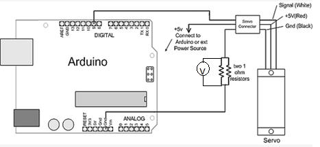
Figure 1: Circuit (Voltage showed on voltage meter will be equivalent to current draw from the servo) 

By Tien Dang

Objective:
For the Hexapod project, one of requirement is to determine the maximum current and to make sure the battery provide enough power for 18 servos to be run simultaneously and safely.

Servo Current:
In order to determine the maximum current, a trade off study has been done on the Power HD 1501 MG servo. We found out that the current drawn may reach up to 2.3 A.

http://www.pololu.com/file/0J729/HD-1501MG.pdf

To make sure the test is accurate; we performed a current test for our project to determine that the current will not exceed 2.3A. The maximum weight of the Hexapod (2066.74 grams which equal to 4.55 pounds), we used objects that has equivalent weight tie to the servo as following pictures.

figure 2

Figure 2:  Two parallel resistors were used to measure the current output following (figure 1 schematic).

Demonstration video for current testing:
https://www.youtube.com/watch?v=NhzRON_y3eg&feature=youtu.be

figure 3

Figure 3: Servo Strength Test

figure 4

Figure 4 : Object weight (2066 grams = 4.55 lbs)

After the test, we established that the maximum current with the 4.55 pound load is 450mAh at 6V.

Battery Choice:
Since there will be 18 servos that going to be used for the Hexapod,  the Turnigy 5000 mAh 2S 30C LiPo pack battery will be the sufficient choice in term of value and weight. Although the Venom battery might be a better choice because it can provide a much longer lifespan for the hexapod to operate (around 1 hour of operation) but due to its pricing ($50 plus shipping) and weight (288 grams which is 0.645 pounds) compare to the Turnigy battery ($20 plus shipping) and weight (275 grams which is 0.606 pounds).

http://www.hobbyking.com/hobbyking/store/__16202__Turnigy_5000mAh_2S_30C_Lipo_Pack_USA_Warehouse_.html

The Turnigy battery can deliver a high discharge rate, which equals to 300A. At the worst case scenario, the maximum current that needed for 18 servos is 81A. So this battery is a perfect choice to supply power for the Hexapod with a minimum duration of 7.5 minutes.

Formula to calculate discharge rate and duration:

Discharge rate = Battery Capacitor * Battery Capacitor Rating

Discharge Duration = (Battery Capacitor / Total Current Drain)

Conclusion:
After doing calculations, the Turnigy 5000mAH 2S 30C LiPo pack is a good choice to supply power for 18 servos with duration more than 7.5 minutes. The only problem that we encountered is the safety requirement. Due to the battery high delivering rate of current and power, we need to use opto-isolators and voltage regulator to protect the servos as well as the ADK board.

Mission Objective

By Mason Nguyen, Project Manager
and Elaine Doan

A hexapod is a six legged robotic capable of moving in all six degrees of freedom forward/backward, left/right, up/down with the combination of pitch, roll, and yaw rotations.  The objective is to deliver a hexapod that will need to operate safely during class room demonstration, capable of matching the speed with the rover, must be able to travel in a forest like setting while maneuvering over obstacles and must be built within $500 budget.

Requirements

  1. Hexapod will match the speed of the rover traveling on a surface with the speed of 0.20027 m/s or 7.8 inches/s as defined by the Rover Team.
    1. To match the speed of the rover, a calculation and verification testing will be performed so that Hexapod will have a walking speed of 8 inches in 1 second. 
    2. The hexapod will operate safely while navigating in a class room environment by operating a LiPo battery protection circuit in order to prevent the batteries from falling below or exceeding above the safe functioning point and avoid drawing too much current from the battery.
      1. Use power supply to mimic the battery and test and verify the performance of the protection circuit.
      2. The hexapod movement will be wirelessly controlled by the Arxterra Control panel via the Android Phone Arxterra app. Also it will utilize the phone camera to obverse the environment.
        1. Verification testing will be performed base on the Arxterra control panel test plan.
        2. The hexapod will travel and maneuver over obstacles 2.5 inches high at the designated terrain showed in figure (1 and 2).
          1. Angular swing of leg servos including Femur and Tibia servo will be calculated, and an2.5 inch object will be created in the classroom environment to test and to verify the maneuverable ability of the Hexapod.
          2. The project is anticipated to be within $500 range. However to improve the hexapod, the project budget could increase from extra components the team planning to add.
          3. The hexapod is expected to fully assembled by May 1st,2014. If time permits, the team will be adding more modifications. Demonstration will be presented by May 14h, 2014.

 figure 1

Figure 1. Location of the hexapod and spider bot Testing Terrain

figure 2

Figure 2. Route of the hexapod and spider bot going to travel.        


Opto-isolator

 By Chau To

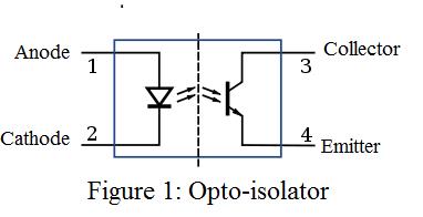
Optoisolator is a component that transfers the signal between 2 isolated circuits. It consists of an LED and a phototransistor as shown in (Figure 1). When a signal is applied at anode (cathode is usually connected to ground), the LED will emit light that shines on the base of the phototransistor turning the transistor on. The optoisolator is used to isolate two parts of a circuit that has different power consumption such as between a micro controller and the DC motor.

Why Optoisolator?

Since the hexapod drives servos directly from the digital pins of the Arduino board, the Optoisolator will provide protection for the board by isolating the servo and Arduino. Since the servo consumes a large amount of current than the board, a power surge could happen and as a result the current from the servo could damage the Arduino. In addition, servo is a very noisy component; the noise could leak to the sensitive microprocessor.

How to connect?

figure 2

As demonstrated from the figure, the output from the PWM digital I/O pins of the Arduino connects the anode than the cathode is connected to ground. The Servo has 3 pins (or 3 wires). The Vdd wire connects to collector of the phototransistor; the other 2 wires connect like figure 2.

Operation: When the PWM is high, the LED lights up; the transistor will switch on. The servo control pin is high, and the servo shaft will rotate.

How to choose an optoisolator?

There are many types of optoisolator in the market. The two important parameters while choosing an optoisolator are the diode forward current and the switching time. The maximum forward current can be found in the data sheet; for the Ardunio the maximum rating forward current should be around 50 to 80mA. The switching time of the optoisolator determines how fast the phototransistor turn on, or what the delay is when the signal passes through the isolator. Nowadays, optoisolator has very fast switching time in micro-seconds.

The hexapod team will use a PS2501-4 Optoisolator 4-channel (4 Optoisolator in 1 IC) to operate the robot.

 Datasheet can be found at: https://www.sparkfun.com/products/784.

figure 3


Hexapod Final Model

By Mason Nguyen, Solid Works model by Vinh Kim

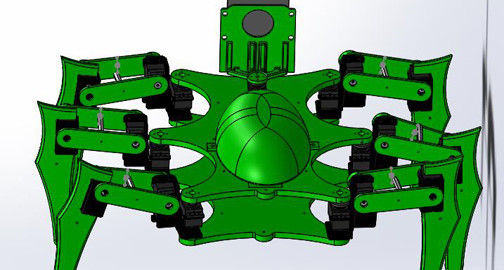
After many working hours, Vinh has finally created the real world final 3D hexapod model including the mounted with the cellphone. The hexapod will operate using 19 servos, 18 servos will serve as the hexapod movement while 1 servo will mount at the front to hold the cell phone. Vinh also modified few parts such as extending the femur length in order for the hexapod to travel over objects easier. We are on our final phase of this model and currently making pieces out of resin. Silicon molding will take place after the pieces are finished.

figure 1
Figure 1: Cell phone holder

figure 2
Figure2: Front Servo mount 

figure 3
Figure 3: Cellphone Samsung Galaxy S2

figure 4
Figure 4: Hexapod Final Model (Front) 

figure 5
Figure 5: Hexapod Final Model (Back)

Hexapod Forward and Backward Movement Calculation and Algorithm

By Chau To

Introduction:
Hexapod uses the tripod gait (3-leg combined showed in Figure 1) to perform forward and backward movement. In order for the Hexapod to move in a straight line, it is required all of the servos such as shoulder, femur, and tibia servo to be operated simultaneously. This blog post will give a detail calculation for the angle that each servo needs to make to compensate with one another. This blog post will also introduce the algorithm for the Hexapod forward and backward movement.

Hexapod Movement Analysis and Calculation:
The Hexapod will use 3 legs at the same time for movement as showed in Figure 1.

 figure 1

Each leg composed of a femur and a tibia and is controlled by 3 servos: shoulder servo, femur servo and tibia servo as showed in Figure 2. 

figure 2


 Forward and backward movement analysis:
When the Hexapod is moving, if the Tibia servo does not rotate, the Hexapod body will be shifted by the “x” distance (bottom picture in figure 3.) The purpose of the following calculation is to find the angle of the Tibia and Femur to compensate and to prevent the “shifted body problem.”

Let’s declare the variable like in figure 3:

figure 3


  • F is the length of the Femur (from the shaft of the Femur servo to the shaft of the Tibia servo)
  • T is the length of the Tibia (from the shaft of the Tibia servo to the ground)
  • α is the angle of the Tibia assuming that the initial position of the Tibia is perpendicular to the ground.
  • β is the angle of the Fumur assuming that the initial position of the Femur is parallel to the ground.
  • A is the project of the leg on the ground
    • θ is the angle the shoulder servo rotates
    • x is the distance that the body is shifted

 Let’s α’ be the new angle of the Tibia servo to compensate the x distance:

 The angle that the Tibia servo has to adjust:

 In order to balance the Hexapod, the Femur servo also has to rotate to a new angle

Let’s y is the length the Femur need to compensate like in Figure 4

 figure 4

Let β’ be the new angle of the Femur servo to compensate the x distance:

 The angle that the Femur servo has to adjust:

Example: Hexapod matching the speed of the Rover 0.2m/s
In order to match the speed of the Rover, each Hexapod step needs to be 4 inches assuming that the Hexapod takes 2 steps in 1 sec, and the speed of the Rover is 8 inches/s

Let the length of the Femur: F = 3 inches, length of the Tibia: T = 6 inches, and α = β = 300

  • A = 6sin(30)+3cos(30) = 5.5980 inches

To reach 4 inches, Let θ = 450  à Hexapod step will be: Asin(45) = 3.958 inches.

So, with this setting, the Hexapod should be able to match the speed of the ROVER!!!

Let calculate the angle of the Tibia and Femur for the forward movement:

  • x = A – A cos(θ) = 5.5980-5.5980*cos(45) = 1.159 in
  • α’ = 43.88660
  • ∆α = 43.8866 – 30 = 13.88660 (from initially 300 to 43.8860)
  • y = 0.8718 in
  • β’ = 120
  • ∆β = -180 (from initially 300 down to 120)

In summary, in order for the Hexapod to move in straight line with a step of 4 inches with the settings in the example, the shoulder servo needs to rotate 450; the tibia servo need to rotate an extra 140 and the femur servo also needs to rotate an extra 180.

Movement Algorithm:
Screenshot (33)

Delay is very important because it requires certain time for each servo to rotate. Therefore, each delay makes sure that the previous stage is completed. Maximizing the delay also increased the performance of the Hexapod. 

At the final stage when the shoulder servo rotates back to –θ, i.e it means that the servo rotate to the initial angle before the robot move. The delay between each rotation is very important and needs to be precise because each angle of the leg servos might be different from each other.

3D Model!

By Mason Nguyen, Project Manager
Solid Works simulation by Vinh Kim

Solid works model:

In order to build a durable and low budget hexapod, resin molding would the primary component for our team to use.  The robot is developed based on a previous version which is focused on the straight-line walking. To enhance its ability to adapt to the terrain, each leg has three revolute joints driven by Power HD 1501 servos. Wasting no time, Vinh Kim our manufacturer started working hard on 3D initial design for our hexapod in Solid Works.  Our main priority we would focus on would be the hexapod shoulders. Both robots had the same dilemma where their legs bent forward while walking and ended up tumbling due to an enormous amount strain from the heavy body weight.

To correct that error, we will be limiting the amount of materials that going to be placed on the hexapod. Also, aluminum brackets will serve as a strong supporting pillar on the hexapod shoulders when operating.

Over the weekend, Vinh has been busy working on the Hexapod body design. Full 3D body assemble will be posting up later around the middle of this week.

3D Body:

 3dbody

Height and Width = 11 by 9.8
6 large holes is .30 in
26 small holes each .06 in

Femur:

 femur

Width = 4.05 in
Thickest = .276 in
Height = .95 in

2 large holes is .30 in

8 small holes each .06 in

Tibia:

 tibia

Height = 6.34 in
Width = 1.75 in
Thickest = .354 in
4 small holes each .06 in

Bracket:

brack

Height = 33 mm
Width = 54.18 mm

16 small holes each .06 in
Aluminum bracket to support the hexapod shoulders

This week goal is to assemble our 3D model!

Vinh Kim is working hard to create and assemble a perfect 3D model. We will have it by the end of this week.  

Meanwhile, Chau To our computer programmer continues working hard to program our servos with the edition of the Adafruit driver.

Tien Dang who is our communication engineer also lends the team a hand by assisting Chau with the programming and putting together our hexapod prototype.

Here is a video of our hexapod prototype where we demonstrating how the servos will rotate and operate.

Hexapod ADK board

By Mason Nguyen
ADK board tested and programmed by Chau To, Tien Dang and Mason Nguyen

ADK Board
Based on previous objective, the team is to build a hexapod using the wireless control interface. In order to achieve that goal, we need to use the ADK Mega 2560 board where it has the ability to connect to the Android phone and control it wirelessly.

mason1
ADK Microcontroller Mega25 Cappuccino Board

Description:
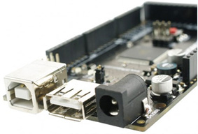
ADK board came with a power jack, a USB connection, an ISCP header, and reset button. Also the board can connect up fifty four outputs/inputs pins. Those pins contained four UARTs with hardware serial ports, sixteen pins inputs, and fifteen pins PWM outputs.

The team decided to use this board instead of the Uno because it can regulate up to 18 servos without the servo shield controller. Moreover, it’s easier to code compared to the Uno where it required using servo shields controller (2-16 channels Adafruit servo controller board or 1-24 channels) and Uno board also needed to use library provided from the servo controller shield to code as well.

For each Power HD servo, it has 3 pins. One pin contains a control V+ and the other contains V-. V+ pin goes to the servo and the V- pin will be grounded. Digital Pin 30 to pin 47 of the ADK is use to connect the servos. Furthermore, algorithm test will be performed to test the maximum operation of the servos being used will only be 10 as the same time.

The efficiency of a voltage regulator, defined as is an important quantity of its performance, especially when comes battery life or heat. In order to protect the board, we will be using a voltage regulator to limit the current spikes.

We concluded that the Mega2560 can support up 50 digital I/O pins so it will be enough to run our Power HD servos.

mason2
ADK Board where the power supply connected to the voltage regulator and from the voltage regulator it connected to 18 servos.

Here is the video from the servos testing!