Spring 2016 3-DoT Goliath Research and Intro
Ayman Aljohani (Project Manager)
Tae Lee (Mission Systems & Test)
Kevin Moran (Electronics & Controls)
Rickeisha Brown (Manufacturing Division)
Jerry Lui (Manufacturing Division)
By: Ayman Aljohani (Project Manager):
The 3-Dot Goliath is a new project that will be working with a new board referred to as the 3- Dot board.
As a project manager, I will be responsible of my team’s final product, and making sure it meets the customer’s requirements (level 1 requirements) which are:
- low-cost ( $ 90 total)
- less 3D- printing time ( 6 hr maximum),small size Goliath look.
- successfully compete in a laser-tag (optical transmission device)battle with 3-DOT Spider project.
- sensor placed horizontally on the rover with zero degree along x-axis,located at a height of 3 inches above the ground.
- When getting tagged three times, the rover should be disabled.
- the rover should be piloted via a live camera view only.
- looks of the RoSco has to be cool
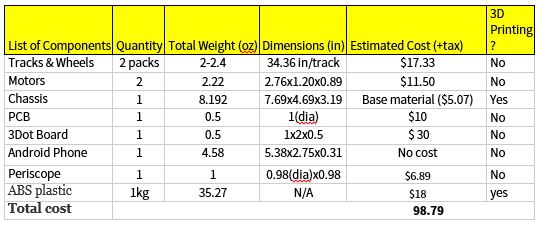
From researching past projects, we have our preliminary budget as follows:
In order to meet those requirements, I have developed a work breakdown structure (WBS) where the the work is broken down into tasks assigned to each division with a deadline.
A prototype version of the project is schedule to be tested on week 5 of the semester.
A research on sensors in terms of (field of view, cost, safety, and interference from outside source) will be assigned to Systems engineer .Based on the research results, the type of sensor will be determined to be one of the following:
IR – LED – Laser – Ultrasonic
- cost
- field of view
- safety
- interference from another external source i.e lights of the room, distance
The research will be joined efforts with our opponent robot team (3DOT Spider).
One important decision should be made as soon as possible is the type of communication devise used in laser-tag battle.
Source materials:
By: Tae Lee (Mission Systems & Test) :
Source Material:
- Battery Comparison,NiCd vs NiMH vs. LiPo Battery Packs, 12-04-13,https://www.arxterra.com/battery-comparisons/
- System and Subsystem Requirements, Level 2 and Level 3 Requirements, 10-31-2013 https://www.arxterra.com/system-and-subsystem-requirements/
- I.Y. Laser Tag Electronics, Head, 2003, Sensors, http://www.lasertagparts.com/mtsensors.htm
- Project Summary, Major Project Features, 12-20-2013, https://www.arxterra.com/project-summary/
- Robot Block Diagram, http://web.csulb.edu/~hill/ee400d/Technical%20Training%20Series/04%20Robot%20Block%20Diagram.pdf
- How to Make a Fritzing Diagram, 12-28-2014, http://web.csulb.edu/~hill/ee400d/Technical%20Training%20Series/08%20How%20To%20Make%20Fritzing%20Diagram.pdf
- What is Arduino?, Fall 2015, http://web.csulb.edu/~hill/ee400d/Technical%20Training%20Series/02%20Intro%20to%20Arduino.pdf
Introduction
The 3D Dot Rosco is a new project that will require a little bit of research. We will be working with a new board referred to as the 3D Dot board.
Some of my responsibilities are performing
- Verification and validation
- Creating level 1 requirements
- Creating the product breakdown structure.
- Able to integrate everything together to create a product that meets the customer’s expectations.
- Power Distribution
- Testing of servos, motors, and sensors
From researching past projects I have noticed they used the Arduino board, Arduino motor shield, and a Bluetooth module that will be used to program a rover to do various tasks [7]. However, the new 3D dot board now incorporates all the hardware into a single board that will be used to control and perform various tasks on the rover. The 3D dot has dimensions 1.38 x 1.73 inches making it portable and convenient when printing 3D parts for the RoSco. Using the Arduino programming language (C++) we will then code and test the servo, motor, control panel, and the Bluetooth module[7].
Review of Literature:
Trade Off Studies of Batteries Review:
The blog post provided information on the research to determine which types of batteries will be suitable for the rover.
Notes for Requirements:
The research that was conducted on the type of batteries seemed unnecessary. This section should be replaced with a tradeoff study on the uses of different batteries. The group provided with informative information on the characteristics of the battery. However, it is more important to provide calculations to determine which battery will last longer for the rover. This requirement of comparing batteries does not contribute with moving the design forward. It would be better to narrow down a few batteries and documenting the amount of current that can be produced by the battery. Next step will to determine the milliampere-hour by adding up all the currents drained from each device to determine the total current. By doing this we can than calculate an approximate value of how long the rover will last by multiplying the total current with the desired operation time [1].
Level 2 and Level Requirements Review:
The rover team provided a good understanding of the level 2 requirements before building the product. They performed research on the terrain for obstacles and the distance that is needed to travel to fulfill the requirement. This included simple calculations to approximate the distance that was needed to travel. In addition, provided information and calculation of determining the required speed of .05 m/s. The next requirement was to determine a battery that will be used on the rover to last 20 minutes. Performing a simple calculation, they were able to determine the type of battery needed (890mAh) [2].
Note on Level 2 Requirements:
A recommendation to improving the blog is to combine the level 2 and level 3 requirements. An example of this is when they discussed the Power and the Power Storage. These sections are closely related and should be combined to make it clear to the reader of choosing the battery that will be used on the rover [2].
I agree with most of the level 2 requirements; however, the power storage will be modified because of the various components that will be used on the rover. The rover will be using a Bluetooth module, 3D Dot Board, laser, laser sensor, and two motors. This will require different type of battery that will power these components. In addition, the speed requirement will be changed by the customer needs.
Laser Communication Device:
We need to implement a sensor that is able to receive a certain wavelength from a laser. Once the laser hits the sensor it will send a signal to an LED or a buzzer to indicate we got hit by the enemy. The laser and the sensor will be connected to the 3D dot board and controlled by a wireless controller. This field will be further researched to be implemented on our rover [3].
New Requirements:
- Battle with spider bot
- Control methods (ex. Bluetooth, Axterra, or Both)
- Sound indicator (ex. Detect when hit or firing)
- Have fun
System Block Diagram:
The systems engineer provided a satisfying block diagram that shows the electrical interface of the rover. This includes the connections for the motor, illuminator, pan & tilt motor, and other components powered by the battery. We will be able to apply a similar block diagram with a few changes to help us create the new rover [4]. These changes include the laser, laser sensor, and the 3D Dot board.
By : Kevin Moran (Electronics & Controls):
Sources material :
Double Gearbox Motor
For more info on batteries
http://batteryuniversity.com/learn/article/understanding_lithium_ion
Level 2 Requirements: (Based on requirement to make a “low budget” and “cool” rover)
- Motor selection
In this year’s project we will be using the 3DoT board which comes with a motor shield and a voltage booster from 3.5V to 5V to control the motor speed. I will be testing the board to ensure it meets the requirements to power the rover. The motors should not exceed a combined force of 5V since that is the board’s limitations
- Battery Life
In order to meet the level one requirements for a game of laser tag, the length of the game must be decided in order to ensure the batteries chosen for the task of powering the rover last until the end of the game. The selection of the batteries will depend on their mAh, their discharge rate, and size. Since our rover is the next generation and because of level 1 requirements, we must ensure it fits in the overall design of rover.
- Laser Tag Game
Level 1 requires that a game of laser tag be played between the Rosco team and the Spider bot. The length of the match is still to be determined. Lasers will not be allowed in this laser tag game. An LED will be used in its place. In order to be able to hit a target, the LED must be focused on the objective.
Rover from previous generations:
In order to build a next generation rover, I read the documentation on previous projects, trying to learn from their successes but also their mistakes. To demonstrate the effectiveness of the 3DoT board, our rover must exceed previous expectations and results. Below are a few of the experiments done by previous groups.
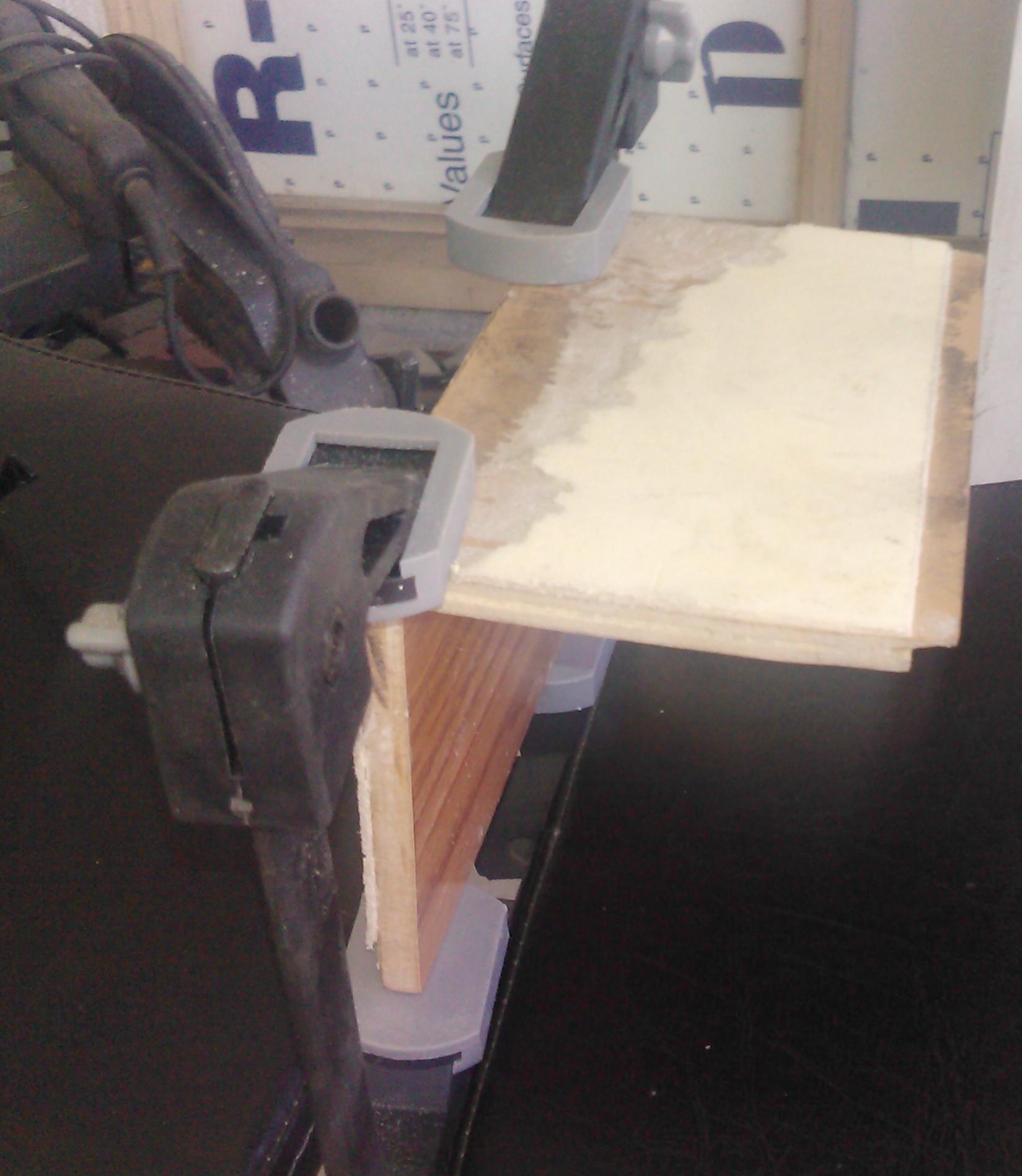
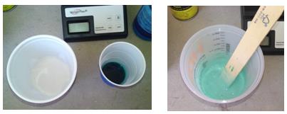
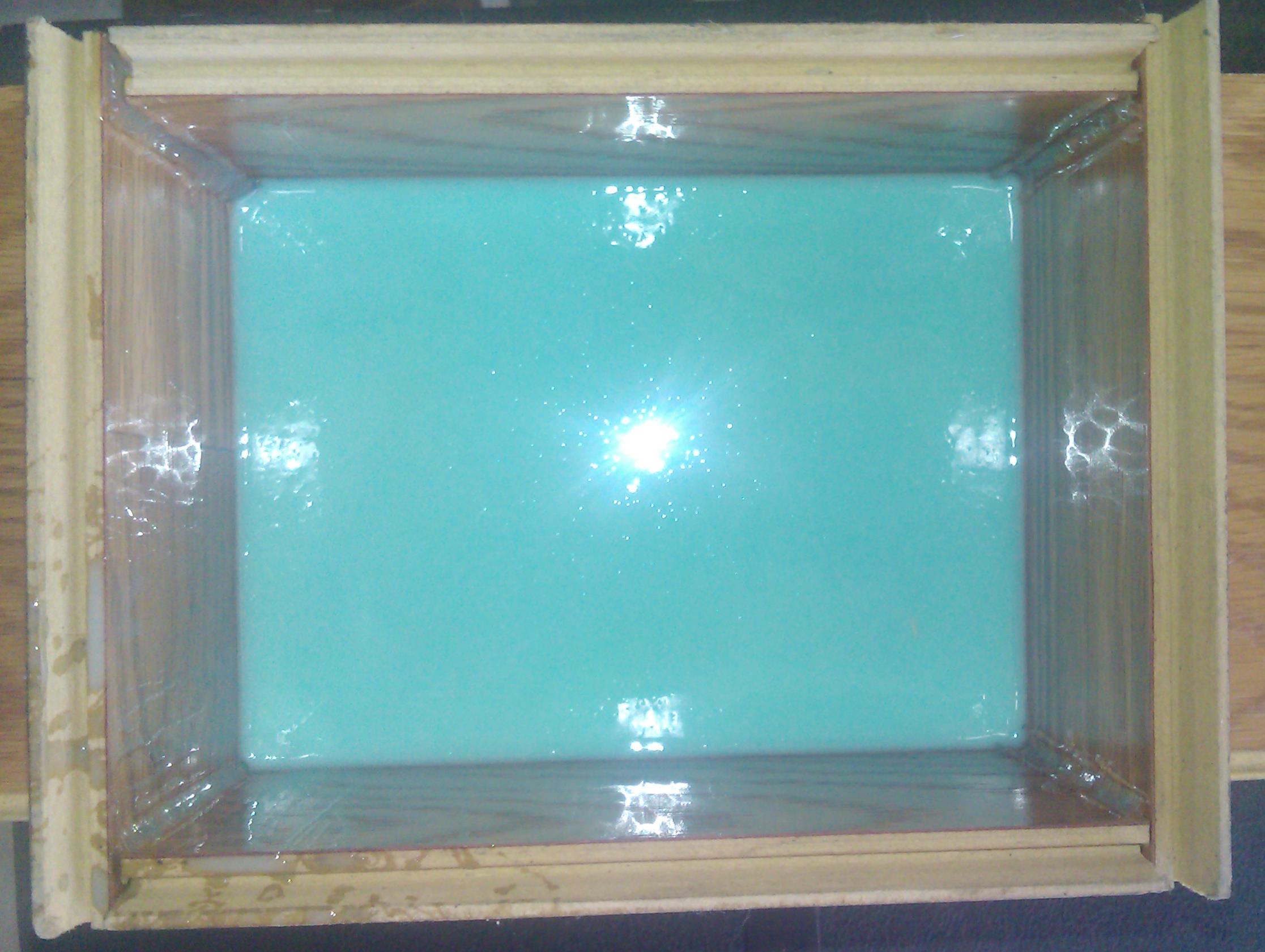
- Waterproofing Servo Experiment
In order to ensure the survival of the rover through its respective test course, the team needed to waterproof their servos to ensure full functionality in wet conditions, and completion of the required task. They enclosed the PCB in waterproof box. They had to spray the servos with plastic dip and submerged them under water for thirty seconds in order to prove they were safe to work in wet conditions. The only problem I see with this way of waterproofing is in the long run of the project. For our specific project we will not be able to waterproof this way, for we are not using servos. However, since we are using a prototype 3DoT board we need to be extra careful to protect from any outside interference, such as a single drop of water. All of our circuitry must be inside the rover and protected by our 3D printed rover.
- Field of Vision Experiment
In order to fully simulate a soldier crawling through a barbed wire course, the designed their rover to avoid obstacles, to match the speed of a soldier, and visualize what a soldier sees in the crawling position. They tried to find the information on the internet but were not successful, so they decided to perform an experiment on field of vision. They needed the field of vision of a HTC Evo phone.
- Power Budget:
The majority of the power was used by 6 different servos and 4 different motors. They needed to know the current the rover uses in order to figure out if their batteries were enough to complete the task. They were given batteries with 700mAH capacity, 7.2V batteries were used on previous semesters. By building their prototype, they were able to determine the exact current their rover would use when it was operational. They discovered that their batteries allowed them to run their rover for 40 minutes. For our project I need to determine how much power the laser will use, and for how long our game of laser tag will last. I need to ensure sufficient battery life for the motors and the laser circuitry. Since it is our first time using the 3DoT board, I will also need to run experiments and seeing how it functions and if it uses up much battery life to function since it’s such a compact design
New Ideas to meet level 1 requirements
Since the rover has been done by previous teams before using the Arduino plus a motor shield along with other components, in order to make our project a new generation we must improve on previous models. However, we must be realistic, we will not be reinventing the motor or the batteries used for the rover. Our focus will be to improve on previously known data. We will choose a similar motor and batteries but according to our 3DoT board, to ensure full cooperation amongst the subsystems. Below are some ideas to meet the level 1 requirements
- Motor
- We will research if 2 separate motors, or a single double-gearbox motor with individual control for the sides works best with the 3DoT board. The location of where the motor is placed will also play an important role, as it will allow for maximum torque and efficiency
- Battery Life
- Since the 3DoT board has a place for a lithium battery, we will research and see if a battery that can fit there can meet all of our requirements. Such as the voltage, the amperage needed during a certain amount of time, and the discharge and charging rates. Since our goal is to reduce costs by reducing the size, it would be ideal to just have 1 set of batteries. We must also figure out a way to charge the battery once it is already in place. I have thought of creating a USB adaptor and placing it on the side of the rover to recharge the batteries as needed. We must also be able to determine the charge of the battery at any given moment.
- Laser Tag Game
- In order to ensure a successful game of laser tag, I have suggested adding the “laser” to the pen tilt that will be holding the phone and the periscope. The point of any game is to try and have a good time (usually by winning). If we are able to have the laser point in the direction of the center of the periscope, we can potentially be able to target the other team by moving the pen tilt until their sensors are in our sights. This will meet the level 1 requirements by reducing the amount of single moving parts, and allowing our team a successful game of laser tag.
- Crazy Idea
- Since our point is to demonstrate the ability of the 3DoT board to power a rover by itself, I have suggested trying to take that a step further. If we were to be able to have two android devices control the rover simultaneously, our rover will be very successful. Person 1 would control the movements of the rover and speed, while person 2 will be control the pen tilt and trying to hit the laser sensors. Both persons would have access to the camera on their devices.
By: Rickeisha Brown (Manufacturing Division):
Source Material :
- Rosco Fall 2015 Custom PCB Manufacturing, Pg. 1, December 19, 2015, https://www.arxterra.com/rosco-custom-pcb-manufacturing/
- RoSco Budget, Pg. 1, October 11, 2015, https://www.arxterra.com/rosco-budget/
- Micro Rover Design Manufacturing, Pg. 1, May 12, 2015, https://www.arxterra.com/micro-rover-design-manufacturing/
- Micro Rover Final Design and Dimensions, Pg.1, May 12, 2015, https://www.arxterra.com/micro-rover-final-design-and-dimensions/
- Micro Rover Final Eagle Schematic, Pg. 1, May 4, 2015, https://www.arxterra.com/micro-rover-final-eagle-schematic/
- MyBot, Pg. 11-13, http://web.csulb.edu/~hill/ee400d/Project%20Folder/Robots%20and%20Drones/Track%20Rover/Track%20Robot%20S’12/Tracked%20Robot%20PDR.pdf
Manufacturing our rover incorporates the actual publishing and printing of the PCB board, soldering IC components and other necessary components to the IC board, along with designing 3D structure components. We will use Eagle Cad to draft our design of circuit boards, create a Gerber file and place an order with a PCB manufacturing company of the Manufacturing Division Manager’s choice. It is vital that we confirm with systems and controls a final PCB board design before moving forward with Eagle Cad and Gerber files prior to printing. It is our goal to utilize production time effectively for adequate testing time.
As stated, we are responsible for the 3D design of rover components on a computer software that allows us to do so. For the sake of time ease and access, our manufacturing team will use SolidWorks. SolidWorks will allow us to draft all parts required to manufacture our rover including: the chassis, gears, battery holder and shell.
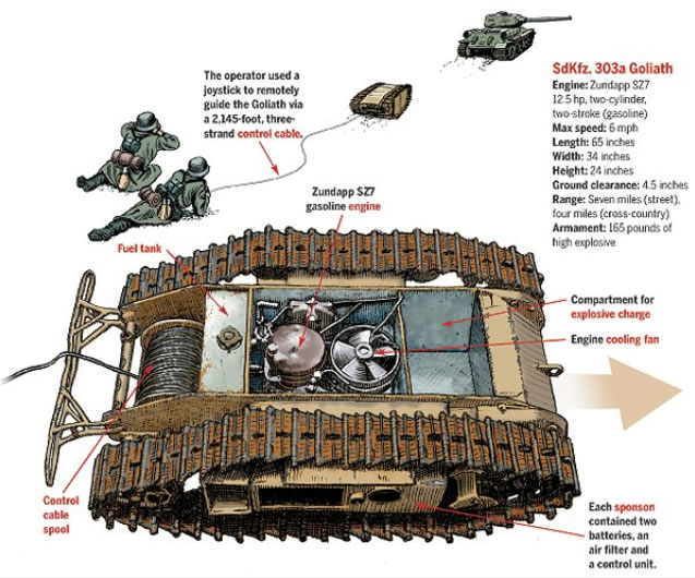
The customer requests that our manufacturing team design a rover which mimics the German Rover Goliath. The German Rover Goliath has a distinct height and length ratio, such as 1:3. However, the most recent rover designs are replicas of Mars Rover and/or NASA’s Curiosity Rover, which have a height/length ratio of 3:1. Goliaths requirements:
- Lower Cost (comparison to recent RoSco specs)
- Minimizing use of 3D-printing
- Smaller/Compact design
- Smaller PCB
- 3D Printing Time: 6 hrs.
- Chassis
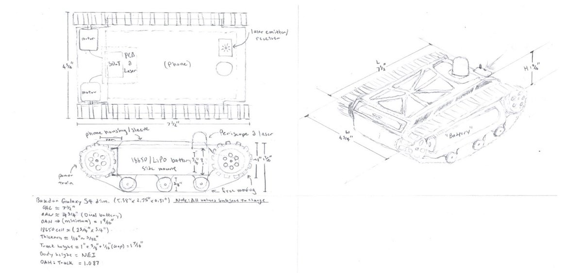
- Dimensions: 7.69×4.69×3.19
- Miscellaneous bolts (prints provided by Division Manager: Kevin L.)
- Chassis
- Goliath Replica
- Tracks & wheel design
- Chassis-body structure includes phone, PCB & 3 Dot wiring components
- One level structure: no neck attached to pen tilt
- Pen Tilt replaced Periscope
- Range of view: Dependent on periscope specs-90 degree angle turns
Estimated total weight of Goliath Rover: 1.88-2.00 lbs
The manufacturing division will be responsible for the generation of an Eagle Cad design of the PCB Board, a 3D model of our Rover design using SolidWorks, & the calculation of material and supply needed to build the desired design.
By: Jerry Lui (Manufacturing Division):
Sources materials:
http://www.toybuilderlabs.com/blogs/news/13053117-filament-volume-and-length
http://www.amazon.com/gp/product/B001VZJDY2?refRID=BT3DN2GHRMF7CEJ988CY&ref_=pd_ybh_a_4
Level 2 subsystem requirement
Chassis material has to be light weight (at least under 1.63lbs)
- Based on the previous Rosco project, the prime material to use for 3D printing would be ABS.
- The overall weight must at least be less than the previous teams Rosco chassis weight of 1.63lbs.
The overall cost has to be low (<$80)
- As per customer suggestions 3D printing should be used. This will cut down on costs.
- ABS is priced, on average, $20 per kg or $9.07 per pound which can significantly reduce weight compared to PLA.
A game has to be implemented in conjunction with the 3Dot Spider-bot team
- A led has been suggested to replace the original laser tag system as per customer request.
The Rover must be similar to the german Goliath ROV
- A prefabricated, commercial track has been proposed to meet the customer objective of having a wheel-tracked system.
Suggestions
- The body of the old Rosco was fairly bulky which accounted for the majority of the 3.25lbs. A more skeletonized body was proposed to help minimize the weight, speed up printing time, reduce costs, and to make it look aesthetically pleasing as per customer objectives.
- The reduced weight of the body will also minimize the strain on the motor(s), and tracks thus increasing product longevity.