Hexapod System Diagram
By Chau To
This blog post contains the system block diagram, fritzing schematic diagram, breadboard diagram, and a bonus MATLAB code for angle calculation of the Hexapod movement.
Hexapod system block diagram:
 Fritzing schematic diagram:
Hexapod connected servo directly from Arduino ADK Digital I/O pins.

Fritzing Breadboard Diagram:
The digital pins we used are pin 30 to 47 for leg servos. Pin 26 for Camera servo.

The protection circuit such as:
- Opto-isolators are connected between the Arduino pins and servo pin can be found at: https://www.arxterra.com/opto-isolator/
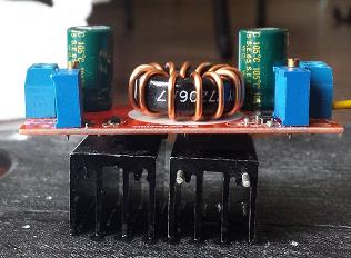
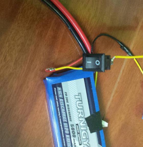
- Voltage regulator is connected between the battery and servos and Arduino board is available at: https://www.arxterra.com/voltage-regulator/
BONUS:
This is the bonus MATLAB code for my “angle calculation” blog post (available at: https://www.arxterra.com/hexapod-forward-and-backward-movement-calculation-and-algorithm/)
This code calculated the angle where the shoulder, femur, tibia have to make and compensate with each other so that the hexapod can move forward or backward steadily.
Please read the link for blog post provided above to understand the input and output parameters of this function:
function [new_a,del_a,new_b,del_b] = cal_ang( T,F,alpha,beta,theta )
%Inputs parameters: T, F, alpha, beta, theta
%T = length of Tibia
%F = length of Femur
%alpha = inital angle of Tibia
%beta = inital angle of Femur
%theta = inital angle of shoudler
%Outputs:
%The New and the adjustment angle for alpha
%The New and the adjustment angle for beta
A = T*sind(alpha)+ F*cosd(beta);
x = A – A*cosd(theta);
new_a = asind((T*sind(alpha)+x)/T);
del_a = new_a – alpha;
y = T*cosd(alpha)-T*cosd(new_a);
new_b = asind((F*sind(beta)-y)/F);
del_b = beta – new_b;
fprintf(‘The new alpha is: %.2f\n’,new_a)
fprintf(‘The adjust in alpha is: %.2f\n’,del_a)
fprintf(‘The new beta is: %.2f\n’,new_b)
fprintf(‘The adjust in beta is: %.2f\n’,del_b)