By Vinh Kim, 3D Modeling and Manufacturing
Introduction:
Here I will show you how to perform a Stress test using Solidworks and SimulationXpress Study for the Hexapod leg and bracket design to determine its maximum stress level.
Leg Stress Testing:

Figure 1
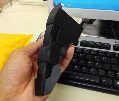
First, open Solidworks and open the leg design the user wants to test.
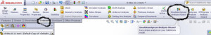
Figure 2
Click on “Evaluate” and next on the top right click on “SimulationXpress Analysis Wizard”
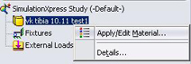
Figure 3
Now, on the box on the left side using the mouse, right click, and click on the “Apply/Edit Material”

Figure 4 a
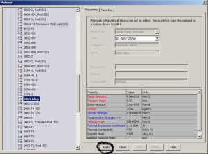
Figure 4 b
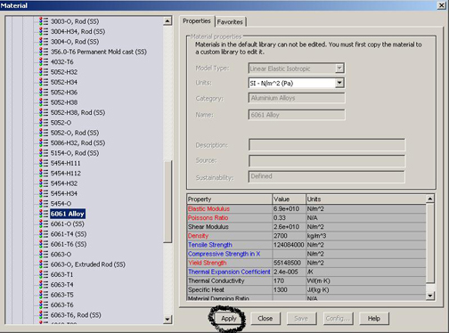
A Material box will show up. Now pick any material that the user wants to test. I picked 6061 Alloy because SolidWorks already had the value in auto set so simply click apply and close.

Figure 5
Now, right click on fixtures than click on fixed geometry.

Figure 6
The Fixture box will show up. As shown, here I clicked on the four holes than a green arrow will pop up and that means that this will be the precise location where the user chose. When done, just click on the green check mark on the left side.
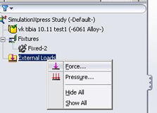
Figure 7
Now, right click on the External Loads and click on the Force and apply the force.
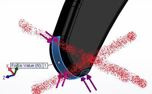
Figure 8
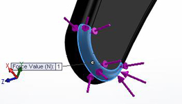
Figure 9
When the leg is sweeping, Figure 8 shows the wrong way of applying the force at the bottom on the leg and Figure 9 shows the right way of applying the force at the bottom from the side.

Figure 10
Now in the Force box, I set the force to 500 N and click on the green click mark
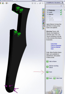
Figure 11
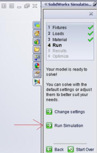
Figure 12
When finish setting the force number, in the left side the user will see a box (similar to Figure 11) than click next three times and click Run Simulation (Figure 12)
Here is the video of the leg sweeping: http://youtu.be/z0AmgpNLJIg
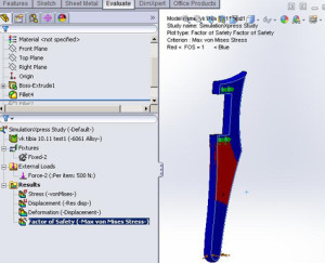
Figure 13
Click on the Factor of Safety (-Max von Mises Stress-) and the user will see a lot of red that mean that the force of 500 N is pretty high, so I am going to lower the force and rerun the study until we see all blue and that will be are maximum force.
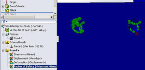
Figure 14
At 102 N, we see a little red.
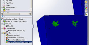
Figure 15
At 101 N, we see no more red, so this is our maximum force for this leg design.
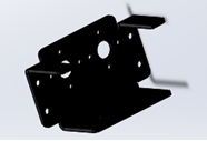
Bracket Stress Testing:

Figure 16

Figure 17
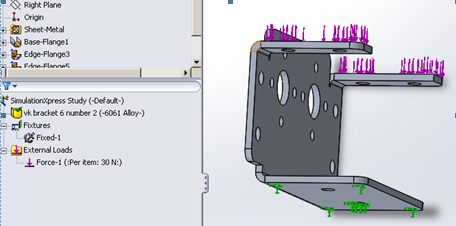
Here I am using 6061 Alloy again and applying fixtures in the bottom (green arrow) and force of 30 N on the top (purple arrow).
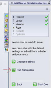
Figure 18
On the left hand side click next three times and run simulation.
Here is a video of the bracket bending: http://youtu.be/RigGvNsRHT4
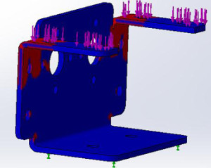
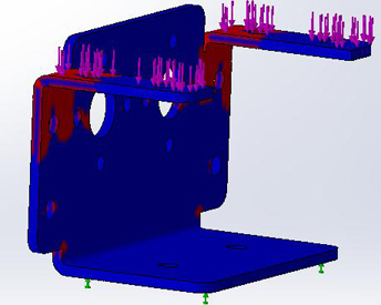
Figure 19
This is at 30 N and you can see all the red, which is not good because it will break. Rerun the test again now lowering the force down.

Figure 20
Here we find out that the maximum of this bracket is 6 N.
Conclusion:
It is recommend to manufacturer that when designing any types of robotic model. They should always consider of using Solidworks SimulationXpress Study to check their design and use different material to run simulation to test their design if its strong enough to handle all those pressures and burdens that will be placed on the robot.