Hexapod Coding Preferences

 By Chau To

  • Introduction:

This blog post will discuss some issues of the servo library (Servo.h) and how coding of the Hexapod was built including functions and subfuctions as well as some tips and troubleshooting.

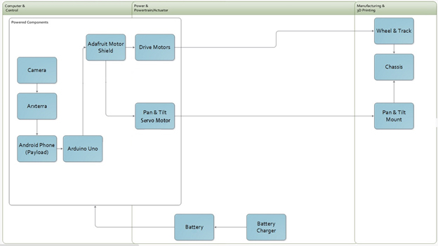
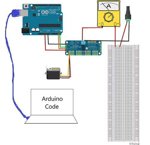
Note: Hexapod team drives 19 servos directly from the Arduino board (digital I/O pins), and it uses the built-in Servo.h library functions such as “write” and “attach” as the main code to rotate the servo shaft. If your hexapod uses an additional servo controller boards such as the Adafruit etc, some of the materials discussed in the post would not apply in that situation.

  • How to create object servo in the Servo.h library:

Since the coding will require “for” loops, creating individual servo object such as servo1, servo2, etc.. Similar to the example in the Ardunino websites is impossible. The only way is to create an array of servo object. How can we do it? We can define a number of servo then call the servo library to create and array of servo object:

#define number_of_servos 19
Servo servos[number_of_servos];

So, we will have an array of servos; in this example, we will have array of 20 servos. Each servo will be appearing like this servo[1], servo[2], etc… NOW! We can put these into for loop. For example: servo[i].write(180).

  • Array:

Array is very important. As mentioned above, when we run “for” loop we need to use array because it will optimize our coding. An array of digital I/O pin is a great example since we need to attach each servo to a specific pin on the Arduino. Here is a sample code:

int pins[] = {30,31,32,33,34,35,36,37,38,39,40,41,42,43,44,45,46,47,48};

void set_servos() {

  for (int i=0; i<number_of_servos; i++)  {

    servos[i+1].attach(pins[i]);

     }}

The above example is a simple function I wrote to attach the pin to the servo. My digital pins will be from pin 30 to pin 48 of the ADK board.

The same concept applies for the servo’s shaft angle rotation. If user wants a specific servo to rotate at a specific angle, they can make an array of angles and run it in a for loop. More detail about array of C++ can be found at: http://www.cplusplus.com/doc/tutorial/arrays/

  • Subfunctions:

Subfunctions are smaller functions that will be called in a main or larger function. Breaking a long and complex function into smaller subfunctions is very useful because it’s easier for the user to double-check and debug the code.  For example, one of the main function of the hexapod is run which includes 2 stages; first stage is moving the femur, tibia, and shoulder to a new position, and second stage is to bring them back to the initial position. So, we can break these 2 stages into 2 subfunctions. And, even smaller subfunctions for controlling and debugging.

  • Serial Monitor:

Serial Monitor can be turned on by Ctrl+Shift+M after uploading the code into the Arduino board. The serial monitor is extremely useful when testing the code. It’s used to keep track of the codes and fix all the bugs before uploading to a real model. This is the sample of the serial monitor added in my set_servo function that was discussed in the previous part:

void set_servos() {

 for (int i=0; i<number_of_servos; i++)  {

    servos[i+1].attach(pins[i]);

    Serial.println(“attach pin”);

    Serial.println(i+1,DEC);

    Serial.println(pins[i],DEC);

  }}

With these serial function added in, I can monitor for my loop as well as to see which servo had attached to which pins. The serial monitor is available at: http://arduino.cc/en/reference/serial

Note: In order to run the serial monitor, in the setup you have to call the serial.begin

void setup()

{

 Serial.begin(9600);

figure 2

Figure 2

System/Subsystem Design

by Suhyun Kim

System Block Diagram

block 

The image above provides an overview of how each component is linked together within the rover. 

Camera/Phone:
From a remote location, using the Arxterra interface we will be able to communicate via the phone and camera.  The camera will provide an image to the Arxterra interface.  Through the phone, we can use the interface to communicate with the microcontroller.

Microcontroller:
The microcontroller subsystem includes an Ardiuno Uno and a Motor Shield.  The Uno will be the bridge between the phone and the motor shield.  The motor shield is used to control the 2 motors and 2 servos on the rover.

Battery:
The rover will have several batteries.  One dedicated battery to power the microcontroller and one to power the motors and servos.  The batteries must provide enough power for all of these components until the end of the mission.

Motors/Servos:
The motors will drive the wheels.  The motors must provide enough torque to move and enough RPM to fulfill our speed requirement.  The servos must provide enough torque to pan and tilt and must provide a range of vision as described in the test plan.

Detailed Cost

By Maxwell Nguyen and Anthony Vo

The first link below provides the BOM for the standard RoSco as provided by Arxterra.  The second link sums the price of each part in order to provide a projected cost of the standard RoSco.

Bill of Materials:
Standard RoSco BOM

Standard RoSco Cost:
https://www.dropbox.com/s/kpw4iobx1h1ova2/standard%20rosco%20bom.xlsx

The link below is the projected cost of the rover taking into account of parts replacement.  This link provides a complete BOM, which includes parts description, quantity, price, and source.

New Rover BOM:
https://www.dropbox.com/s/439vaho8fhycdth/Rover%20Projected%20Cost%20new.xlsx

Task Descriptions

by Maxwell Nguyen

  • 1.      Trade off studies: 1 week

Compare different motors and servos.  Determine which motor and servo will best meet our subsystem requirements.


 2.      Test motor: 1 week
Test/record current draw and RPM of motors at different voltages.


 3.      Test Servo: 1 week
Test/record current draw of servo depending on required torque.  The required torque will be simulated by lifting an object.  Verify torque load of servo.

 4.      Mirror Study: 1 week
Test mirror functionality with phone camera.  Record a video with mirror in place at different angles.

 5.      Battery test: 1 week
Measure/record current and capacity of the battery.

 6.      H-Bridge Study1 week
Research and report the functionality and purpose of an H-bridge.  The new Adafruit Motor Shield comes with an H-bridge on board.  Research will be done on how to implement the H-bridge into the rover design.

 7.      Program testing:  1 weeks
Learn and write up a program to test servos and motor shield.  Coding will most likely be done in C++.

 8.      Motor shield test 1 week
Confirm that the motor shield is working properly by testing injunction with motors and servos.

 9.      Track research 2 weeks
New track design will be based on tank treads.  The goal will be to design tracks that can be printed as separate individual pieces.  The pieces will be able to attach to each other to create a single belt.

10.     Phone to Arxterra test:  1 week
Download and install Arxterra app onto the teams dedicated Samsung Galaxy S3.  Confirm that the phone can communicate to Arxterra and provide and image via phone camera.

11.     Arxterra to Arduino test:  1 week
Confirm that the Arxterra is communicating to the Arduino Uno.  Confirm that the Arxterra user interface can relay signals to the Arduino and Motor shield.

12.     Remodel Head:  2 weeks
Design a new head that will support the phone and allow for panning and mirror tilting.

13.     Print parts:  3 weeks
Send orders to manufacturing division to get parts printed

14.     Assemble Rover 1 week
Rover and track assembly will be done.  Some sanding and reshaping may be required if parts do not fit together.

15.      Conduct Test Plan: 2 weeks
Test and verify that rover can achieve the requirements laid out in the test plan.

Test Plan

By Suhyun Kim and Robert Licari

For our new design of Rover, we will do some tests such as electrical tests, software tests and functional tests. The electrical tests would be minor and basic tests, and software and functional tests would be main tests for our project.

Electrical Tests:  1 week duration
Electrical Tests will mainly include Current and Voltage Tests of battery, motor, servo converter and microcontroller. 9VDC motor supply and 9V UNO supply will be tested to ensure that the supplies are providing the proper amount of current and voltage required to power the rover.  Also, the two of DC motor and Servos will be tested for their current draw because all of motors are core parts in controlling the Rover.

   Test Type       Test sub-type
Battery 12VDC Motor Supply
  9V UNO Supply
Motor DC Motor (x2)
Servo Servo (micro)
Microcontroller Arduino Uno

Motor Shield


Software Tests: 1 week duration
On the Software Tests, we will test how applications of Arxterra are well connected to Arduino Uno and Control Panel. Also, we will check Image Processing parts. These tests would influence on how the Rover is exactly navigating through the course.  We will confirm that the Axterra interface can communicate through the phone with the microprocessor.

Test Type Description
Applications with Control Panel How applications are well connected to Control Panel
Control Panel with Arduino Uno How Control Panel are well connected to Arduino Uno


Functional Tests: 2 week duration
Functional Tests is our project’s main tests. It will include Speed Tests, Turn Tests, Pan Tests and Tilt Tests. In speed tests, we will do forward speed and backward speed tests on flat surface and natural surface. We will check that Rover can navigate like calculated speed on any surfaces, especially natural surface.  To navigate through designated course, the Rover has to turn left side and right side. Therefore, we will do 90 degrees left and 90 degrees right turn tests from forward (normal position). Pan tests will be same to turn tests. Also, because rover will have a mirror to secure views, we need tilt tests.  We will test 45 degrees upward tilt and downward tilt from normal position. 


Test Type Test sub-type Description Desired Results
Speed Tests Flat surface A 10 meter “dash” across a flat, smooth, surface.  


Calculated Speed @0.200277 m/s

  Natural surface A 10 meter “dash” across a natural, earthen, surface. (loose earth).
  Flat surface Test

(Reverse)

A 10 meter “dash” across a flat, smooth, surface backwards.
  Natural surface

(Reverse)

A 10 meter “dash” across a natural, earthen, surface. (loose earth) backwards.
Turn Tests Right Turn A 90 Degree Turn Right from Normal (Forward) Position  
  Left Turn A 90 Degree Turn Left from Normal (Forward) Position  
Pan Tests Pan Right A 90 Degree Pan Right from Normal (Forward) Position  
  Pan Left A 90 Degree Pan Left from Normal (Forward) Position  
Tilt Tests Shutdown A Test -45 Degrees from Normal (45 Degrees)  
  Normal A Test at 45 Degrees  
  Look-up A test +15 Degrees from Normal (45 Degrees)  
  Sky box A Test +45 Degrees from Normal (45 Degrees)  


Rover Team Servo Holder and Mirror

By Vinh Kim, 3D Modeling and Manufacturing

Introduction:
Using SolidWorks, the Rover project manager Maxwell had requested me to design him a servo and mirror holder.

figure 1 

Figure 1: Servo holder

 figure 2

Figure 2: Mirror

figure 3 

Figure 3: Servo holder and mirror with cell phone.

How to use STL file cutting

By Vinh Kim, 3D Modeling and Manufacturing

Introduction:
To print out 3D materials, the Manufacturing Division Manager Ali Etezadkhah will provide his own 3D printer that can print 5 by 8 in parts. In some cases, the 3D printer cannot print larger parts because its size is too small. In order to cut down the size of the model, we have to use a program call STL (Surface-Tesselation-Language) so that it will fit the 3D printer for parts print out.

STL Step by step guide:
Here we have a model from the rover team where we have to use STL file to cut the parts.

figure 1 (1) 

Figure 1

Step 1:

 figure 2

Figure 2

Go to www.netfabb.com and download the netfabb Basic since SolidWorks program cannot cut the STL file. Now open the netfabb program than open the STL file.

Step 2:

figure 3

Figure 3

Here we see that the model length is 140 mm (5.51181 in) and the width is 150 mm (5.90551 in), (as expected, the model is too large).

Step 3:

Next, go to Extras and click on the Free cut (Pro).

figure 4

Figure 4

Step 4:

figure 5

Figure 5

A product information menu will pop up which telling the user that we need netfabb Professional is required to use. It costs 1,799.00 USD to buy on the netfabb website. In this case, we do not need to buy the license program since the netfabb basic will cut the STL model too so just close the window.

Step 5:

figure 6

Figure 6

From the box on the right hand side, we can see cuts (X,Y,Z). Just use the X and move the bar to 70 mm because 140/2 = 70 mm and click Execute cut.

Step 6:

figure 7

Figure 7

Now, on the bottom right side, click cut.

Step 7:

figure 8

Figure 8

Next, click on the model (right side) and it will turn green. Now, right click on the mouse and go to export part as STL and save it. Finally, use the same method for the left side of the model.

Conclusion:
For the hexapod, we also used this program to break down our parts since the body is too big for the 3D printer (size … ). The STL file will cut it into four pieces and later will be printed parts by parts. Everything will be compressed into a STL file and sent to Ali to print out the pieces. 

Current Test of the Power HD High Torque Servo 1501 MG

Experiment Conducted by: Matthew Clegg (Controls – Spiderbot), Elaine Doan (Systems Engineering Division), and Kristine Abatay(Project Manager – Spiderbot)

Test Setup written by: Matthew Clegg and Kristine Abatay

 Discussion and Results written by: Elaine Doan

A test will be performed in attempt to find the current the Power HD High Torque Servo 1501 MG consumes during operation of the Spiderbot or Biped when 6 volts is applied.  From the test, the idle current of the Power HD High Torque Servo 1501 MG will also be identified.

Test Setup

The following setup was used for this test:

Blog7_image2


The test was run using breakout boards since they will be used to power the many servo motors in the final construction of Spiderbot. A plastic indicator was attached to the wheel of the servo, which was placed in front of a protractor since the test code used was based off of PWM adjustment as opposed to angle. The following image shows the test code that was used. Matthew Clegg modified the code that was provided by Adafruit (the brand of the breakout board used) to cater to this test:

Blog7_image3


The final construction of Spiderbot will involve the use of metal brackets to securely connect the servos with the designed components, so a metal bracket was also used in this test. In order to acquire accurate current readings and properly mimic the motion that Spiderbot’s legs will use, small weights were attached to the end of the bracket.

The estimated weight that a single leg servo on Spiderbot will have to support came out to be 437.55 g. This value was acquired using estimates provided by SolidWorks for the designed components and actual weight measurements from a scale for components that we had. The total is comprised of a single femur and tibia component, as well as three servos to account for a single leg, and 1/6 of the chassis design with all of the components it will hold (i.e. Android phone, pan and tilt platform). The total mass that was tested went up to as high as 500 g in order to account for the possibility of undershooting the final mass, keeping in mind the total mass that the servo can handle with the extended arm attached. The following image provides an idea of the approach taken in finding the current for varying lengths of the servo arm:

Blog7_image4


The first panel of the image shows the metal bracket and the small weights that were attached to it. In order to maintain a constant test mass with a varying arm length, the weights were first placed on the inner and outer portions of the bracket without exceeding the initial length of the arm, as depicted in the second panel of the image. Finally, the masses were stacked on the bracket to extend the length of the arm, as shown in third panel, and more current measurements were obtained.

 The current read through the multimeter varied constantly throughout the test, so the values that were recorded were the largest values that appeared consistently on the multimeter for each angle value. A quick video depicting the setup of this servo test can be found in the link below:

http://youtu.be/b5Dv5LfQsCQ

Discussion and Results

When working with servos, there are two currents worth noting: the idle current and the stall current. The idle current is the current consumed by the servo when it is not performing but connected to the power source. It is important to identify the idle current because it will provide users with the upper bound on how long a battery powered application can run. The stall current is the maximum current drawn by the servo when it is performing. The stall current will provide users with the minimum current requirement for the power supply. The actual current a servo consumes during operation will vary between the idle current and stall current. Servo currents usually are not specified by the manufacturer and the user is required to run tests to find the idle current and stall current. It’s easy to measure the idle current since it is low, constant, and only requires a simple connection to a power supply. A standard servo such as the Power HD High Torque Servo 1501 MG will have an idle current around 0.01 -0.03 amps depending on the power supply. Stall currents are more difficult to measure because stalling a servo can result in a damaged servo. A standard servo such as the Power HD High Torque Servo 1501 MG will have a stall current around 1 amp (finding the stall current of the Power HD High Torque Servo 1501 MG will not be attempted in this test.  Finding the current a servo draws during normal operation of the Spiderbot and Biped will be attempted instead). The current will be approximately linear with the supply voltage, so the currents drawn at 7 V will be almost double those at 4 V. Adjusting the rotational degrees of the servo will typically draw more current linearly. Increasing the torque by ten times will typically draw ten times the current.

Part A
IDLE CURRENT

Idle Current at 6.0 V = 0.03 amps

Part B
SHAFT ROTATION VS CURRENT

 Blog7_image5

The graph shows how the current draw is affected by the increasing rotation of the servo’s shaft from 10 to 90 degrees. The current drawn increases steadily by approximately 10 mA as the rotation degrees increase by increments of 10 degrees. 

Part C
TORQUE VS CURRENT


Blog7_image6


The graph shows how the current draw is affected by the increasing torque from 0.10 to 6.48 kg•cm. The current drawn increases by approximately 40 mA as the torque increase by increments of 1 (kg•cm). 

Current Draw

Figure 1: Circuit (Voltage showed on voltage meter will be equivalent to current draw from the servo) 

By Tien Dang

Objective:
For the Hexapod project, one of requirement is to determine the maximum current and to make sure the battery provide enough power for 18 servos to be run simultaneously and safely.

Servo Current:
In order to determine the maximum current, a trade off study has been done on the Power HD 1501 MG servo. We found out that the current drawn may reach up to 2.3 A.

http://www.pololu.com/file/0J729/HD-1501MG.pdf

To make sure the test is accurate; we performed a current test for our project to determine that the current will not exceed 2.3A. The maximum weight of the Hexapod (2066.74 grams which equal to 4.55 pounds), we used objects that has equivalent weight tie to the servo as following pictures.

figure 2

Figure 2:  Two parallel resistors were used to measure the current output following (figure 1 schematic).

Demonstration video for current testing:
https://www.youtube.com/watch?v=NhzRON_y3eg&feature=youtu.be

figure 3

Figure 3: Servo Strength Test

figure 4

Figure 4 : Object weight (2066 grams = 4.55 lbs)

After the test, we established that the maximum current with the 4.55 pound load is 450mAh at 6V.

Battery Choice:
Since there will be 18 servos that going to be used for the Hexapod,  the Turnigy 5000 mAh 2S 30C LiPo pack battery will be the sufficient choice in term of value and weight. Although the Venom battery might be a better choice because it can provide a much longer lifespan for the hexapod to operate (around 1 hour of operation) but due to its pricing ($50 plus shipping) and weight (288 grams which is 0.645 pounds) compare to the Turnigy battery ($20 plus shipping) and weight (275 grams which is 0.606 pounds).

http://www.hobbyking.com/hobbyking/store/__16202__Turnigy_5000mAh_2S_30C_Lipo_Pack_USA_Warehouse_.html

The Turnigy battery can deliver a high discharge rate, which equals to 300A. At the worst case scenario, the maximum current that needed for 18 servos is 81A. So this battery is a perfect choice to supply power for the Hexapod with a minimum duration of 7.5 minutes.

Formula to calculate discharge rate and duration:

Discharge rate = Battery Capacitor * Battery Capacitor Rating

Discharge Duration = (Battery Capacitor / Total Current Drain)

Conclusion:
After doing calculations, the Turnigy 5000mAH 2S 30C LiPo pack is a good choice to supply power for 18 servos with duration more than 7.5 minutes. The only problem that we encountered is the safety requirement. Due to the battery high delivering rate of current and power, we need to use opto-isolators and voltage regulator to protect the servos as well as the ADK board.

Mission Objective

By Mason Nguyen, Project Manager
and Elaine Doan

A hexapod is a six legged robotic capable of moving in all six degrees of freedom forward/backward, left/right, up/down with the combination of pitch, roll, and yaw rotations.  The objective is to deliver a hexapod that will need to operate safely during class room demonstration, capable of matching the speed with the rover, must be able to travel in a forest like setting while maneuvering over obstacles and must be built within $500 budget.

Requirements

  1. Hexapod will match the speed of the rover traveling on a surface with the speed of 0.20027 m/s or 7.8 inches/s as defined by the Rover Team.
    1. To match the speed of the rover, a calculation and verification testing will be performed so that Hexapod will have a walking speed of 8 inches in 1 second. 
    2. The hexapod will operate safely while navigating in a class room environment by operating a LiPo battery protection circuit in order to prevent the batteries from falling below or exceeding above the safe functioning point and avoid drawing too much current from the battery.
      1. Use power supply to mimic the battery and test and verify the performance of the protection circuit.
      2. The hexapod movement will be wirelessly controlled by the Arxterra Control panel via the Android Phone Arxterra app. Also it will utilize the phone camera to obverse the environment.
        1. Verification testing will be performed base on the Arxterra control panel test plan.
        2. The hexapod will travel and maneuver over obstacles 2.5 inches high at the designated terrain showed in figure (1 and 2).
          1. Angular swing of leg servos including Femur and Tibia servo will be calculated, and an2.5 inch object will be created in the classroom environment to test and to verify the maneuverable ability of the Hexapod.
          2. The project is anticipated to be within $500 range. However to improve the hexapod, the project budget could increase from extra components the team planning to add.
          3. The hexapod is expected to fully assembled by May 1st,2014. If time permits, the team will be adding more modifications. Demonstration will be presented by May 14h, 2014.

 figure 1

Figure 1. Location of the hexapod and spider bot Testing Terrain

figure 2

Figure 2. Route of the hexapod and spider bot going to travel.