Subsystem Requirements: Power Budget

by Robert Licari and Anthony Vo

Power supply of the Rover:
Rover must provide sufficient power to clear the course of 50m.

To ensure that the rover is able to complete its mission in a timely fashion, the rover’s load cannot exceed 6.72 Wh. For this to be true, we must consider how much power and current draw will go into each of our major components powered by this battery pack. In accordance with this math, we should be able to run approximately 13 W of power during the duration of 30 mins. Keeping this in mind, we will continue with the analysis of our motors.

DC Motor:

120:1 Plastic Gearmotor 90-Degree Output


Typical operating voltage: 6 V
Gear ratio: 120:1
Free-run speed @ 6V: 85 rpm
Free-run current @ 6V: 70 mA
Stall current @ 6V: 800 mA
Stall torque @ 6V: 75 oz·in

The single most important consideration that we have is with our DC Motors. We will be running two motors which will alter the above specifications as follows:

 Stall current @ 6V =>            1.6 A
Stall Torque @ 6V =>            1.05924 N-m   (converted from 150 oz*in)

Given this information, we will be able to determine that ~1 N-m of torque is where our DC motor will stall a will effectively put us dead in the water. So long as our torque remains underneath this value we can safely say that our current draw will be under 1.6 A and that our motors will not stall.

 For this purpose, we will be working backwards. Our considerations will work from an outlandish power involving our Stall values, and we will be able to take steps backward in order to figure out where we want to be in terms of power usage and current draw.

 Therefore, we will, once again, use our power equation utilizing our stall values and our rated voltage:

P_stall = V * I_stall
P_ stall = 6V * 1.6 A

= 9.6 W

This value is our stall power for both of our motors at Stall. Now, we do not wish for our motors to stall because that would be detrimental to our fundamental mission objective of forward motion. Therefore, we will simply scale backwards from our stall power and find a current draw that will fit with the specifications of our battery pack.

 Here are some basic equations demonstrating this:

Let I = P / V
If P = 9 W then
9 W / 6 V = 1.5 A

If P = 5 W then
5 W / 6 V = 0.83 A

 If P = 3 W then
3 W / 6 V = 0.5 A

These current values will be considered when we bring our Rover from rest to forward motion, and are integral to the mission objective. From a purely theoretical standing, the motor will never draw this much power at free-run, but we must also consider that the amount of time that our rover is at free-run speed will be minimal given the nature of the course we must navigate. Taking these into consideration, it is best to err on the side of the worst case scenario in order to avoid the necessity for a new battery pack or motor.

To meet our loose requirement for under 13 W of power consumption, if we consider our motors to draw about 5 W collectively, we are well under the power consumption thus far.

Also, do keep in mind that we are using the specification of 6 V, which can be subject to change as a work-around for our power budget.

Servo Motor:

 Towerpro MG996R 10kg servo
Weight                                    55g
Dimension                              40.7*19.7*42.9mm
Stall torque                            10kg/cm = 0.01 kg/m
Operating speed                    0.20sec/60degree(4.8v)
Operating voltage                  4.8-7.2V
Temperature range               0_ 55
Servo Plug:                             JR (Fits JR and Futaba)

Just like for the DC Motor, we will consider a purely electrical requirement. We will use the same approach that we have used previously but utilize different formulae in order to account for our different specifications.

Our first goal was to find an equation that could accurately and easily find a reasonable power consumption. Therefore, we will be using this equation:

P = ( N * T ) / C_1

For the use of this equation, we will use the fact that N is the number of revolutions per minute (RPM) and that C_1 is a Torque conversion constant related to the desired units of power that follows the below table

We must also consider that our operating speed is in improper units as well. So we will use the conversion provided by our conversion calculator (see Sources), which will give us the following:

0.2s / 60 degrees = 1/300 s/degree

 => ~50 RPM @ 4.8 V

Now that we have our operating speed in RPM, we can begin using our new power equation in order to discover what our stall power is and work backwards just as we did with the DC motor.

If P = ( N * T ) / C_1

Our stall power will be the following:
P_stall = ( N * T_stall ) / C_1
= ( 50 RPM * 10 kg/cm ) / 97.3

= 5.1387 W

This tells us that our maximum power before stall is ~ 5 W at our operation voltage of 4.8V. Now if we work backwards just as we’ve done before:

If P = 5 W then
5 W / 4.8 V = 1.0417 A

If P = 3 W then
3 W / 4.8 V = 0.6250 A

For our application here, we have a tremendous amount of flexibility with the servos. Unlike the DC Motor, the servos will not be running constantly in order to fuel our objective, but we must also consider that there is a finite amount of power that we have at our disposal. Therefore, if we propose that our servos run at approximately 3 W collectively then we can use that in our calculation of our battery life.

Hexapod Forward and Backward Movement Calculation and Algorithm

By Chau To

Introduction:
Hexapod uses the tripod gait (3-leg combined showed in Figure 1) to perform forward and backward movement. In order for the Hexapod to move in a straight line, it is required all of the servos such as shoulder, femur, and tibia servo to be operated simultaneously. This blog post will give a detail calculation for the angle that each servo needs to make to compensate with one another. This blog post will also introduce the algorithm for the Hexapod forward and backward movement.

Hexapod Movement Analysis and Calculation:
The Hexapod will use 3 legs at the same time for movement as showed in Figure 1.

 figure 1

Each leg composed of a femur and a tibia and is controlled by 3 servos: shoulder servo, femur servo and tibia servo as showed in Figure 2. 

figure 2


 Forward and backward movement analysis:
When the Hexapod is moving, if the Tibia servo does not rotate, the Hexapod body will be shifted by the “x” distance (bottom picture in figure 3.) The purpose of the following calculation is to find the angle of the Tibia and Femur to compensate and to prevent the “shifted body problem.”

Let’s declare the variable like in figure 3:

figure 3


  • F is the length of the Femur (from the shaft of the Femur servo to the shaft of the Tibia servo)
  • T is the length of the Tibia (from the shaft of the Tibia servo to the ground)
  • α is the angle of the Tibia assuming that the initial position of the Tibia is perpendicular to the ground.
  • β is the angle of the Fumur assuming that the initial position of the Femur is parallel to the ground.
  • A is the project of the leg on the ground
    • θ is the angle the shoulder servo rotates
    • x is the distance that the body is shifted

 Let’s α’ be the new angle of the Tibia servo to compensate the x distance:

 The angle that the Tibia servo has to adjust:

 In order to balance the Hexapod, the Femur servo also has to rotate to a new angle

Let’s y is the length the Femur need to compensate like in Figure 4

 figure 4

Let β’ be the new angle of the Femur servo to compensate the x distance:

 The angle that the Femur servo has to adjust:

Example: Hexapod matching the speed of the Rover 0.2m/s
In order to match the speed of the Rover, each Hexapod step needs to be 4 inches assuming that the Hexapod takes 2 steps in 1 sec, and the speed of the Rover is 8 inches/s

Let the length of the Femur: F = 3 inches, length of the Tibia: T = 6 inches, and α = β = 300

  • A = 6sin(30)+3cos(30) = 5.5980 inches

To reach 4 inches, Let θ = 450  à Hexapod step will be: Asin(45) = 3.958 inches.

So, with this setting, the Hexapod should be able to match the speed of the ROVER!!!

Let calculate the angle of the Tibia and Femur for the forward movement:

  • x = A – A cos(θ) = 5.5980-5.5980*cos(45) = 1.159 in
  • α’ = 43.88660
  • ∆α = 43.8866 – 30 = 13.88660 (from initially 300 to 43.8860)
  • y = 0.8718 in
  • β’ = 120
  • ∆β = -180 (from initially 300 down to 120)

In summary, in order for the Hexapod to move in straight line with a step of 4 inches with the settings in the example, the shoulder servo needs to rotate 450; the tibia servo need to rotate an extra 140 and the femur servo also needs to rotate an extra 180.

Movement Algorithm:
Screenshot (33)

Delay is very important because it requires certain time for each servo to rotate. Therefore, each delay makes sure that the previous stage is completed. Maximizing the delay also increased the performance of the Hexapod. 

At the final stage when the shoulder servo rotates back to –θ, i.e it means that the servo rotate to the initial angle before the robot move. The delay between each rotation is very important and needs to be precise because each angle of the leg servos might be different from each other.

Motor Trade-off Study

By Anthony Vo

In order to decide which motor will meet our level 1 and subsystem requirements, it is important to conduct a trade-off study of several motors.  The goal of the trade-off study is to compare and contrast the RPM, current draw, torque, and cost of each motor.  From the trade-off study, we will be able to determine which motor will best fit out design specifications.


Type of Motor

plastic gearmotor

GM8

GM9

GM10

GM17

Cost

$5.75

$5.75

$5.75

$9.26

$5.75

           
Voltage (vdc)

6

5

5

5

6

Current (mA) free-run

70

57.6

73.2

24.6

29

Power=IV (mW) electrical

420

288

366

123

174

RPM (speed)

85

70

66

370

32.4

Torque (oz-in)

75

43

43

3.6

69

Torque (kg-cm)  

3.096

3.096

0.26

4.97

Torque (N-m)

0.529

0.303

0.303

0.025

0.487

Reduction

120:1

143:1

143:1

81:1

228:1

Weight (grams)

32

32


5

35

Weight (oz)  

1.13


0.176

1.23

Above is a chart of 5 different motors with a hyper link to each one.  The description and specification for each motor is arranged into a chart for easy comparison.  From the data above, we have narrowed down our motor to 2 choices: the GM8 and the plastic gearmotor.

GM8:
The pros for choosing the GM8 over the plastic gear motor include lower current draw at free-run and lower power consumption.  The lower power consumption allows us to meet our power requirement defined in the subsystem requirements.  However, this motor will not provide the RPM required to achieve our speed requirement at the rated 5 volts.

Plastic Gear Motor:
The pros for choosing the plastic gear motor over the GM8 include higher RPM and higher torque rating.  The higher RPM ensures that our level 1 speed requirement is met.  This motor also provides more torque which will allow the rover to move over more difficult terrain without stalling.

Conclusion:
After comparing the two motors, we are leaning towards the plastic gear motor.  Although the motor is less power efficient, it will still meet the subsystem power requirements.  The plastic gear motor will provide the RPM and torque we need to drive the rover at our speed requirement.

Mirror Study

By Maxwell Nguyen

In order to eliminate the need for larger servos, the rover team will be implementing mirrors to provide vision for the rover.  As compared to lifting a phone, the torque and power require to lift a mirror is substantially less.

Objective:
The objective of this study is to examine whether a mirror used for vision control will provide a clear and undistorted image.

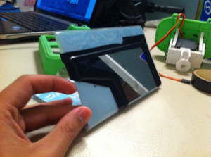
 A study must be conducted in order to verify if mirrors can be used for the pan and tilt vision.  We will use a basic, homemade apparatus to test the camera vision through the mirror.  The apparatus can be seen below and consists of a mirror taped to a small booklet to provide stability and a tilt function.

2 

Mirror apparatus

Equipment and materials:

   -Phone with camera
   -Mirror
   -Tape
   -Small booklet

Procedure:
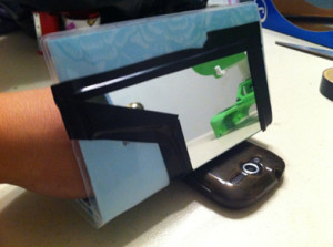
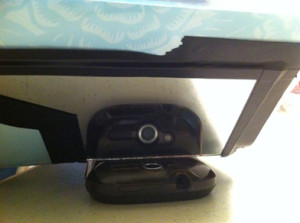
The setup will have the phone placed on a flat surface with the camera facing up towards the ceiling.  The phone will remain stationary throughout the entire test.  The mirror apparatus will be placed directly over the camera.  Using the flap of  the booklet, a tilt function can be simulated.  By turning the booklet/mirror left and right, we can simulate vision control to the left and to the right. 

 3

Test setup

 4

 Test setup(different angle)

Results:

The following short clip provides results to the mirror study.

Conclusion:
Mirrors do in fact provide a clear image for the camera.  Tilting and panning of the mirrors shows no distortion.  From this study, the team will move into designs to implement the mirror on the rover.

3D Model!

By Mason Nguyen, Project Manager
Solid Works simulation by Vinh Kim

Solid works model:

In order to build a durable and low budget hexapod, resin molding would the primary component for our team to use.  The robot is developed based on a previous version which is focused on the straight-line walking. To enhance its ability to adapt to the terrain, each leg has three revolute joints driven by Power HD 1501 servos. Wasting no time, Vinh Kim our manufacturer started working hard on 3D initial design for our hexapod in Solid Works.  Our main priority we would focus on would be the hexapod shoulders. Both robots had the same dilemma where their legs bent forward while walking and ended up tumbling due to an enormous amount strain from the heavy body weight.

To correct that error, we will be limiting the amount of materials that going to be placed on the hexapod. Also, aluminum brackets will serve as a strong supporting pillar on the hexapod shoulders when operating.

Over the weekend, Vinh has been busy working on the Hexapod body design. Full 3D body assemble will be posting up later around the middle of this week.

3D Body:

 3dbody

Height and Width = 11 by 9.8
6 large holes is .30 in
26 small holes each .06 in

Femur:

 femur

Width = 4.05 in
Thickest = .276 in
Height = .95 in

2 large holes is .30 in

8 small holes each .06 in

Tibia:

 tibia

Height = 6.34 in
Width = 1.75 in
Thickest = .354 in
4 small holes each .06 in

Bracket:

brack

Height = 33 mm
Width = 54.18 mm

16 small holes each .06 in
Aluminum bracket to support the hexapod shoulders

This week goal is to assemble our 3D model!

Vinh Kim is working hard to create and assemble a perfect 3D model. We will have it by the end of this week.  

Meanwhile, Chau To our computer programmer continues working hard to program our servos with the edition of the Adafruit driver.

Tien Dang who is our communication engineer also lends the team a hand by assisting Chau with the programming and putting together our hexapod prototype.

Here is a video of our hexapod prototype where we demonstrating how the servos will rotate and operate.

Rover Level 1 Requirements

By Maxwell Nguyen

Level 1 Requirements:

Our top mission requirements are derived from the specifications of the standard Arxterra Rosco.  The requirements will include speed, power consumption, cost, and time.

Speed:
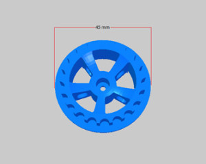
Our rover is expected to move at a speed of 0.200277 m/s.  This is calculated using the standard wheel diameter of 45mm and RPM of the motor. 

Wheel diameter = 45 mm

 wheel

3D model of wheel


Motor Specs:
120:1 Plastic Gearmotor 90-Degree Output

 motorspic

Free-run speed @ 6V: 85 rpm

Velocity calculation:
Radius = d/2
R = 0.045/2
R = 0.0225 mm
Circumference = 2*pi*r
C = 2*pi*0.0225
C = 0.141372 m

Velocity = RPM*C

V = (85 rot * 0.141372 m)/60 sec
V = 0.200277 m/s

Cost:
Must have a lower cost compared to the standard RoSco of $284.13.  The BOM for the standard RoSco can be found in the two links below.  The first one lists the parts and links to find the parts while the second link provides a sum of all the costs of each part.

Parts list and where to purchase them.

Rover Projected Cost List

Time:
The rover must be completed by May 12.  This takes into account CSULB’s final exam schedule and deadline for the project.

Hexapod ADK board

By Mason Nguyen
ADK board tested and programmed by Chau To, Tien Dang and Mason Nguyen

ADK Board
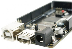
Based on previous objective, the team is to build a hexapod using the wireless control interface. In order to achieve that goal, we need to use the ADK Mega 2560 board where it has the ability to connect to the Android phone and control it wirelessly.

mason1
ADK Microcontroller Mega25 Cappuccino Board

Description:
ADK board came with a power jack, a USB connection, an ISCP header, and reset button. Also the board can connect up fifty four outputs/inputs pins. Those pins contained four UARTs with hardware serial ports, sixteen pins inputs, and fifteen pins PWM outputs.

The team decided to use this board instead of the Uno because it can regulate up to 18 servos without the servo shield controller. Moreover, it’s easier to code compared to the Uno where it required using servo shields controller (2-16 channels Adafruit servo controller board or 1-24 channels) and Uno board also needed to use library provided from the servo controller shield to code as well.

For each Power HD servo, it has 3 pins. One pin contains a control V+ and the other contains V-. V+ pin goes to the servo and the V- pin will be grounded. Digital Pin 30 to pin 47 of the ADK is use to connect the servos. Furthermore, algorithm test will be performed to test the maximum operation of the servos being used will only be 10 as the same time.

The efficiency of a voltage regulator, defined as is an important quantity of its performance, especially when comes battery life or heat. In order to protect the board, we will be using a voltage regulator to limit the current spikes.

We concluded that the Mega2560 can support up 50 digital I/O pins so it will be enough to run our Power HD servos.

mason2
ADK Board where the power supply connected to the voltage regulator and from the voltage regulator it connected to 18 servos.

Here is the video from the servos testing!

Spring 2014 Rover Introduction

By Maxwell Nguyen

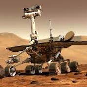
This new semester brings along a brand new team with inventive and innovative minds. The rover team will be aiming to create a brand new and improved design for the RoSco Rover.

The Rover Team includes:
Maxwell Nguyen – Project Manager
Robert Licari – Communications
Anthony Vo – Sensors, Actuator, Powertrain
Suhyun Kim – Image Processing, Computer Systems

Mission Objective:
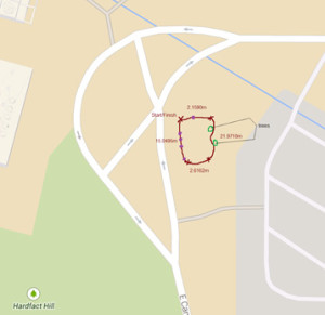
Construct a rover that will be able to navigate through a natural set course shared by the Spiderbot and Hexapod.  The rover must be able to navigate around sprinkler and branches on the course.  The route was determined by the Spiderbot team and can be viewed below.

map
course top view

mapIllo

Course map view

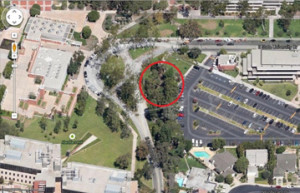
The course is located in the East Wind of campus and is about 42 meters long.

Spiderbot: Chop Suey Returns

By Matthew Clegg, Computer & Control Systems

Chop Suey has returned! David Gonsalez, a member of the Hexapod team from the previous semester, has loaned us the hexapod prototype he built. Having access to an already built prototype will save time and money because we will not have to devote resources to make one. It will also allow me to visualize how the servos will be working to move the legs and body, depending on which type of walk, or gait, the Spiderbot will use.

We scouted the area where Spiderbot will be required to move through and took measurements of obstacles. After previewing the terrain, it seems that Spiderbot may have to switch between two different types of gaits in order to overcome obstacles and move with good speed. The two gaits in consideration are the tripod gait, which will allow for a greater speed on level surfaces, and the wave gait, which is slower but will allow for more stability over uneven terrain.

Further explanation of these gaits can be found in the blog of the previous semester’s Hexapod project.

Sprinkler_Top

The length of some of these obstacles will also affect the distance that the legs of Spiderbot will have to sweep.  This will be determined in part by the length of the legs. The photo above indicates that the maximum width of the obstacles from a top view (both sprinkler heads and branches) measured to 2.5 inches, which is the leg sweep that will be required of Spiderbot.

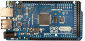
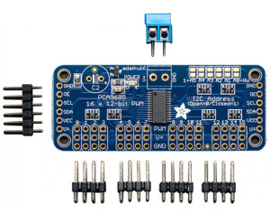
In accordance with the previous semester’s design choices, we have also decided to use the Arduino Mega ADK, as well as the Adafruit 16-Channel 12-bit PWM/Servo Driver in Spiderbot’s design. The Mega ADK will allow for fewer complications when interfacing with an Android smartphone because of the dedicated usb port placed on the board. The Mega ADK will not be able to support the number of servos we will be using (a total of 20 servos!), which is why we will be using servo drivers. The use of the drivers will also free up processing power from the Arduino ADK. These components are shown below:


ArduinoADKFront450px

Image from: http://arduino.cc/en/uploads/Main/ArduinoADKFront450px.jpg


adafruit-16-channel-i2c-servo-controller-1_1

Image from: http://www.robotshop.com/media/catalog/product/cache/1/image/800×800/
9df78eab33525d08d6e5fb8d27136e95/a/d/adafruit-16-channel-i2c-servo-controller-1_1.jpg

The next thing in store for Spiderbot: trade-off studies of servo motors for leg operation of Spiderbot and familiarization with everything Chop Suey has to offer to better our design.

Spiderbot – Life & Times (Vol. 2)

Spiderbot_Logo_smaller

By Kristine Abatay, Project Manager

main()
{
printf(“hello, world!”);
}

It is a new semester at Robot Company and with it, a new Spiderbot!

 Our mission: construct a six-legged robot that will match the speed of the Robot Company’s rover project, operate safely, and have the capability of maneuvering a route in a natural setting.

 This robot will have a spider-like appearance and walk, but with six legs instead of eight, all the while being controlled wirelessly using an application for Arxterra, designed for Android smart phones. Spiderbot will achieve a speed of 0.2003 m/s on a flat surface – the calculated speed using specifications from components of the rover project last semester.

Click here to see the calculation used to determine the speed requirement  

The natural setting that Spiderbot will be able to maneuver is located on the East Wing of the CSULB campus as shown by the following map:

Map

 Our group surveyed the area and created a route for Spiderbot to complete as indicated in the picture above and the total length measured to roughly 42 m. This is the same path that will be used to test both the Rover and the Hexapod projects. A quick run through of the route can be found in the following link:

The pictures below are some of the obstacles encountered while surveying the Spiderbot route. A sprinkler head with a height of roughly 4 inches and a branch with a width of 2.5 inches were the most notable obstacles. These measurements will dictate the overall body design of our Spiderbot. In addition to these design requirements, our Spiderbot will function properly while following the health and safety policy of the engineering department of CSULB (found here: http://www.csulb.edu/colleges/coe/views/safety_and_environment/safety_policy.shtml).

SONY DSC

Our date of completion is set for May 12, 2014 so stay tuned for future updates as we progress in our construction of Spiderbot!