By Nicholas Jacobs – Project Manager
As the Preliminary Design Review approached, Daniel, our Manufacturing Engineer, diligently modeled all of SpiderBot’s pieces in SolidWorks. SpiderBot’s design, originally found at Instructables. com, came with .dwg CAD files that had to be converted into .dfx files, which act as the industry standard for laser printing. This conversion unknowingly created a very expensive problem I’ll talk about shortly. When it came time to print, we erred on the side of caution choosing to construct SpiderBot using a mix of 1/4 inch and 1/8 inch acrylic thicknesses. Excited for being one for being one of the first groups to have a design ready for print, I enthusiastically coordinated a meet-up with the Shop Foreman at CSULB’s Design Center and sent Daniel on his way to print. Not knowing what to expect, Daniel meets up with Foreman and learns that printing consists of $5 upfront and $1 per minute thereafter. Agreeing to this, Daniel begins to print. Remember that expensive problem I mention above? Well 45 minutes later, our parts are still printing-long story short, we spent $89 dollars on our first print for SpiderBot version 1. After talking to Daniel, we had no idea as to what caused this or how to fix it. On the bright side, all our parts were ready to be assembled, but at that point 45% of our $200 budget had been consumed.
Daniel began to scour for answers, not finding anything explicit, he did notice after the conversion process, any part that had a curve or bend was altered- now consisting of what he called ‘infinitesimal’ line segments instead of one smooth curve to make its shape. So when it came time to cut, the laser cutter was literally cutting each ‘infinitesimal’ line segment, hence the super long cut time.

Infinitesimal lines that increase print time.

Leg design with regular curves – faster print time.
We never found a quick fix for a smoother file conversion, Daniel decided to remake each part by hand ( in SolidWorks) to ensure that there were no more ‘infinitesimal’ to hamper our cut time. When talking about this problem during one of our weekly meetings, Daniel did suggest that follow-on semesters take a screenshot of the desired part, import into SolidWorks, and suggests using the ‘Trace tool’ in SolidWorks .
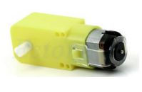
Accepting our losses, we moved ahead assembling SpiderBot while also conducting trade-off studies to determine what DC motors should drive our walking mechanism. At the time, I had two GM3 DC motors laying around from a previous project, and we decided to use in the meantime. Once assembly was complete, we tested our new design, by applying a 9 volt battery to both of the leg motors…it walked-just not consistently. This was mainly due to SpiderBot’s plus size weight of 842 grams, which is including two 31g GM3 DC motors. Hats off to the mail room located within the shipping and receiving building across the street from ECS building for weighing both builds of SpiderBot. After presenting our preliminary design to the class, the customer stated that our design is too big and that we need to downsize.

build_1 – look at nuts and bolts for size comparison.
Reducing the size of SpiderBot isn’t as tedious as you may think. Daniel again found a ‘scale’ tool (mold tools> scale OR insert>features> scale) within SolidWorks that allows you to expediently reduce/enlarge the size of each part by a certain factor. With the infinitesimal lines gone, the creation of a smaller more streamlined design, and all parts planned be recut using 1/8 inch acrylic, we rush to print build 2 eager to see our reduction in weight and size.
$25. That is all our 2nd cut cost to complete. That included $5 upfront cost and then 11 minutes ($11) to cut, plus $9 for a sheet of 1/8 inch acrylic. The cost breakdown is as follows:
$89 + $20 ( materials) = $109 for build_1
$11 + $5 + $9 = $25 for build_2
The corrections made from build_1 to build_2 led to a 77% reduction in price. However, the best is yet to come- our desired mass. After all pieces were cut Daniel quickly assembled SpiderBot build_2, he used a Parallax proto-board from EE 370 Lab to act as a power source to drive both motors.

build_2 – notice how much larger the nuts and bolts appear
With GM3 motors attached, we took build_2 and returned to the post office to check the new weight.

much better…for build_2!!
A breakdown of our mass:
780g + 31g(2) = 842 g build_1
385g (includes GM3s) build_2
Build_2 was a 54% reduction in mass!!
With this significant weight reduction, SpiderBot walks consistently, smoothly and appears to have little to no friction points.
As of 19 April 2017, with the 3Dot board, camera (smart phone – 178g), prototype grappling system, we’re approaching 750 grams. If we would have stuck with Build_1 we would have approached and most likely exceeded 1Kg. During our verification and validation stages over the next two weeks, the SpiderBot team will continue to look for ways to reduce our weight to ensure the best most efficient design.

