BY: Christopher Hirunthanakorn (Missions, Systems and Test Engineer)
Introduction:
The purpose of this blog post is to summarize all of the work that has been done for the software design of the 3DoT David and inform the reader of the final state of the software. It will cover the software flow chart to introduce the tasks the software has to accomplish and then explain the different modules in the software block diagram. Finally, a brief overview of how each module works in the final version of the code will be provided.
Related Level 2 Requirement:
- The 3DoT David shall be controlled by the Arxterra App used on a smartphone.
Software Flow Chart
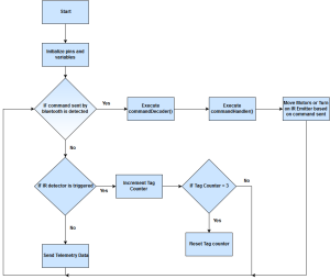
The software flow chart shown here shows what the modified Arxterra firmware that will be programmed to the 3DoT board will do. The program will start by initializing all pins and variables used such as the pins for the Sparkfun Dual Motor Driver TB6612FNG, the IR emitter, IR detector, and speaker. Next, it will check to see if a command is sent via bluetooth from the ArxRobot App. If a command was sent, the commandDecoder and commandHandler functions will be executed and the action related to the command sent will be done. When no command is detected, the program will check if the IR detector has registered a tag from an opposing robot. If it is tagged, a sound will be made and the tag counter will be incremented. When the tag counter reaches three, a song will play, the robot will be disabled for 10 seconds, and the tag counter will reset before the loop continues. If there was no tag detected, the program will send any telemetry data that is required. Currently, there was no requirement for the 3DoT David to send any telemetry back to the ArxRobot App.
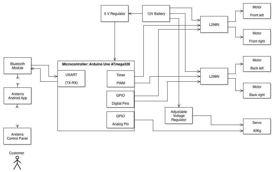
Software Block Diagram
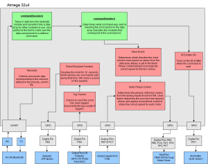
The software block diagram shown here explains what the different modules do and the types of inputs/outputs of each module. The modules are the commandDecoder, commandHandler, Move Robot, Motor Phase Control, IR Emitter On, Tag Tracker, Robot Disabled, and Telemetry.
CommandDecoder Module
For the commandDecoder module, the input is the command data that comes from the ArxRobot App through bluetooth. This data is sent one byte at a time and the commandDecoder module saves this data into an array. Once the entire array is received, this module verifies that all of the data was sent correctly using a state machine and that the command ID matches one of the defined commands. It outputs this array for other modules to use.
CommandHandler Module
For the commandHandler module, the input is the data array containing the command information sent from the ArxRobot App. This module will check the command ID from the array and then execute the corresponding functions for that command. Those functions must be defined individually. If there are any custom commands that need to be added, a corresponding if statement is required to modify the commandHandler module to handle that command ID. There are no outputs from this module.
Move Robot Module
For the Move Robot Module, the input is the command data that comes from the ArxRobot App through bluetooth. This module includes all of the functions required to move the 3DoT David and is only executed when the move command is sent from the app. It uses the functions defined in the sparkfun_TB6612FNG.ino file and a custom function that operates the motors based on the direction of the move command that was sent. The outputs of this module are the control signals for the Sparkfun dual motor driver and the PWM values for the motor speed, which are designated as digital pins PB5, PB6, PC6, PD7, PF5, PF6, and PF7.
Motor Phase Control Module
For the Motor Phase Control module, the inputs are the current outputs from the flexible resistor sensors. This module processes those inputs using the code that was provided by the Electronics & Control Division Manager Jeffery Cool. It will compare the two inputs and determine if one of the motors is moving faster than the other. This works because the two inputs will be equal if the motors are in phase. The module will make the two motors in phase by changing the speed of the motors. The output of this module are the PWM values for the motors.
This module was tested and had a slight improvement to the movement of the 3DoT David but it was determined that it was not necessary. It is not implemented in the final version of the firmware because of the limited number of pins that are readily available on the 3DoT Board.
IR Emitter On Module
For the IR Emitter On module, there are no inputs. It will only be called by the commandHandler module when the correct command is received. The purpose of this module is to send the command signal to turn on the IR emitter and attempt to tag the opposing robot. It is not always on and will only be turned on when the correct command is received. The module outputs the control signal to the digital pin PD1.
Tag Tracker Module
For the Tag Tracker module, the input is the current output from the IR detector. If the signal that is being detected at the digital pin PD0 is low, that means a tag has not been detected. When the signal is high, this module will increment the tag counter which starts at zero. After the tag counter reaches three, this module will call the Robot Disabled module and then reset the tag counter to zero. This module will also create a 5 second delay before it checks the output from the IR detector to prevent consecutive tags. There are no outputs from this module.
Robot Disabled Module
For the Robot Disabled module, there are no inputs. When it is called by the tag tracker module, this module will prevent the robot from responding to any commands for 10 seconds and play a short song to indicate that the 3DoT David is disabled. There are no outputs from this module.
Telemetry Module
For the Telemetry module, the inputs will vary depending on what type of telemetry needs to be sent back to the ArxRobot App. This module will collect the current values from the sensors on the robot and send that information back to the app. It should be called at a maximum frequency of 1 Hz in order to prevent data overload. The output of this module will be a data array that is sent via bluetooth. For the 3DoT David, there was no telemetry that was required.
Implementation of modules
For the Move Robot module, the existing code was designed for operating a rover and needed to be modified to fit our robot’s movement system. With the new movement system design, both motors will need to be controlled at the same time in order to move because each motor is driving one set of three legs. Additionally, the smoothest movement of the legs required the PWM value to be set to the maximum of 255. If it was any less, the motion of the 3DoT David would look very slow and feel weird. Because of the way the ArxRobot App is set up, the user has to press and hold the direction button to increase the speed of the motors to move in that direction. The code was changed so that the PWM value would be a constant 255 and that the leg movements would be fluid.
For the IR Emitter On module, it was decided that the IR emitter will be turned on whenever the 3DoT David is moving and is off the rest of the time. This is because the ArxRobot App can only send one command at a time and the alternative method of controlling the IR emitter would be using a slider on the app to turn it on or off. Implementing this in the code was easily done by incorporating the command into section of the commandHandler function that executed the move commands.
For the Tag Tracker and Robot Disabled modules, code was added to the main loop to check the output of the IR detector and if the 3DoT David should be disabled. The code is executed after the commandHandler function is called and checks if the robot has been tagged. If so, a counter would be incremented and if that counter reaches three, the robot will be disabled. When hit, the speaker will make a sound and the robot will not check for tags for 5 seconds. When the robot is disabled, it will not respond to any commands for 10 seconds and play a short song to indicate this change. All of this is done by using a flag variable to keep track of whether or not a tag has occurred. The flag will be cleared after 5 seconds have passed. When this has happened three times, the code will enter a loop that keeps it from responding to commands for 10 seconds.
Additionally, all of the extraneous code that was a part of the latest version of the arxterra firmware was removed. This includes all of the telemetry and sensor definitions that were left over from older projects that are not being used for the 3DoT David. All of the code used for debugging and testing were also removed or commented out to make sure additional processing time was not being used up. Comments were also added to help future students understand how the code functions.
The final version of the Arxterra Firmware (click here)


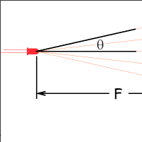
 I did further research online in order to preform calculations that would work with the measurements I do have thus far. The following image is of calculations I found on the magnification (M) in relation to the distance projected from the lens to a wall (d
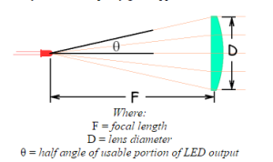 On the webpage I found this picture, it listed a formula for determining the minimum lens diameter. It is as follows: