Spring 2016: 3DoT David Leg Movement Angle Study

BY: Andrew Saprid ( manufacturing engineer)

Introduction:

The leg must be lifted in order for the spider to walk. Supplying 5 volts will be efficient enough to lift the leg, and rotating 360 degrees continuously.

Related Requirements:

Level 2 system requirement states:

The 3DoT David shall use two micro motors for the movement system of the robot.

Leg Study

Calculations are done to find out the angle and the leg lifted off the ground. The calculated  circumference of the 3 cm gear came up to be 4.78 cm. The initial lift of the leg is to be 5 degrees. by using sine to find x, it came to be .42 cm. The final lift is 13.3 degrees. The same method is done which came to be 1.1cm. Subtracting .42cm to 1.1cm, came up to be 0.68 cm off the ground.


           Initial lift: 5 degrees                                                            Final Lift: 13.30 degrees

Screen Shot 2016-04-10 at 3.30.39 PMScreen Shot 2016-04-10 at 3.31.50 PM


The calculations are as follow:

Circumference of the 3 cm gear

C = 2πr  = 2π(0.76) = 4.78 cm

Given 5 degrees for the initial lift

sin(5) = x/4.78

4.78 x sin(5) = .42 cm  

Final lift is 13.30 deg

4.78 x sin(13.30) = 1.1cm

1.1cm – .42cm

= 0.68 cm off the ground

Spring 2016: 3DoT David Motor Driver Control

BY: Kent Hayes (Electronics and Control)

Introduction:

The motor driver on the 3DoT board is the Sparkfun motor driver 1A dual tb6612fng. Therefore Kent bought the actual component and began to experiment with how it will be controlling the motors.

Related requirements

A part of our project requirements includes the following:

  1.  The 3DoT David shall compete with other robots in a game of tag to demonstrate the functionality of the robot.

Motor Driver Control
In order to play “tag” one would have to be able to maneuver in order to get in range of another player as well as dodge being hit by the person trying to tag them. In order for the robot to demonstrate the ability to walk and turn, we will use motors to rotate the legs

MotorDriver_Test_Schematic

(Fig. 1: Fritzing diagram of motor control setup)

The following are pictures of portions of the arduino code used to test motor control:

MotorDriver_Code1_BlogPost

(Fig. 2: Comments for setting up the code to drive the motors)

MotorDriver_Code2_BlogPost

(Fig. 3: Defining the pins and constants for clockwise/counterclockwise rotation)

MotorDriver_Code3_BlogPost

(Fig. 4: Setup and loop code to drive the motors clockwise)

Each motor needs 1 digital pin for sending a PWM signal with values ranging from 0~255 (the greater the value of PWM the more voltage is used and the faster the motor will rotate), and 2 digital pins for determining the direction. The motorDrive function accepts three inputs: one to determine which motor is being used, the other to determine what direction you want the motor to turn, and the final input for the speed of the motor. Once Kent became more comfortable  with the code, he generated an alternative code to make the motors change direction based on user input, thanks to the assistance of Chris (3DoT Systems). The following is the resulting code:

MotorDriver_Code4_BlogPost

(Fig. 5: User input for controlling the motor direction)

Conclusion:

Once the user input code passed the test, Chris successfully came up with the Code to communicate through bluetooth based on the code presented by Kent. Throughout the entirety of the project, we will be referring to this code until we find a way to implement the FSR circuit properly.

Spring 2016: 3DoT David IR Emitter/Detector Testing

BY: Kent Hayes (Electronics and Control)

Introduction:

In order to implement a “laser tagging” system, the electronics and control engineer conducted research and performed tests in order to see that it is possible. You can view the results of the IR Trade off Study in our blog post (insert link to blog here). Taking these results he built the circuit shown in the PCB design blog post (insert link to PCB design process blog) to test the IR emitter and receiver.

Requirements:

  • As a part of the subsystem requirements, this test is to determine if we can achieve the 5ft (2m) of range with the IR emitter/receiver system.


Images of Circuits:

Copy of IR_Test_Schematic

(Fig. 1: Fritzing Diagram of IR System)

Screen Shot 2016-04-10 at 2.19.28 PMScreen Shot 2016-04-10 at 2.29.06 PMScreen Shot 2016-04-10 at 2.20.27 PM

While doing tests for sensitivity, he noticed the more you decreased the resistance being fed into the collector of the BJT, the more effective the IR emitter would become. In addition, the more you increase the resistance connecting from VCC to the detector, the more sensitive the detector would become. The detector was not receiving an IR signal further than 1ft from the emitter. As the components moved closer towards one another, the output voltage of the detector would decrease

IRTestResults

Table of results from varying resistors and ranges

Conclusion:

The best results appear to come when the RDetector is increased and not when R5 is changed. Even then, when we have such a short range which is only 3in. After reading a bit more online, Kent found the only other thing there is to increase the range of the IR emitter is a focusing lens made for LEDs. Depending on how wide the angle of the emitter is, how long the focal length is, and how wide the diameter of the lens is, we can then design our own lens tube. The following image is a table of how one might go about designing their own lens tube with various values:

IR_Test_LensStudy_BlogPost

We have ordered lenses and will begin testing to determine the most efficient design in order to meet the 5ft maximum range requirement.

Resources:

Lense Tube Table | http://www.lasertagparts.com/mtoptics.htm

Spring 2016: 3DoT David PCB Design

BY: Kent Hayes (Electronics and Control)

Introduction:

In order to create the PCB for our 3DoT David, we needed to know what areas the 3DoT board would be lacking. It turns out that the board would not have a signal processing circuit for our Infrared system, a speaker, and phase detection circuit. Therefore, all we needed to do was design an OP-amp comparator with hysteresis (Schmitt Trigger) in order to create a threshold for voltages that we would find acceptable. In addition we designed voltage buffers and hooked them up with flex sensors for the phase detection circuit.

Related requirements:

As a part of the subsystem requirements:

  1. The 3DoT David shall use an infrared LED emitter and infrared detector for the tagging system in the game of tag.
  2. The 3DoT David shall use a small speaker to produce the buzzing sounds to indicate the end of a round in the game of tag.
  3. The 3DoT David shall include a PCB that uses a Schmitt Trigger circuit to convert the analog output from the IR detector into a digital output to be handled by the 3DoT board. It will also have a voltage follower and anti-aliasing filter for the synchronization of the two motors. This PCB shall also provide the connections from the 3DoT board to the peripherals such as the IR emitter, IR detector, and micro motors.

In order to complete this requirement we will being going over each part of the PCB schematic that contributes to fulfilling it.

Signal Processing Circuit (Schmitt Trigger)

The Schmitt Trigger is able to clean up messy signals received from the IR detector and only accept input values that it will recognize as high or low values which will be defined as the threshold. This is important for our game of tag because we do not want just any voltage reading to register as being hit. Based on the voltage values being read at  various distances, we can then properly set the threshold values.  The threshold is will change by varying the resistor values and the Vcc. The following image is a picture of the calculations made by Kent (Electronics and Control engineer) for the design on the Schmitt Trigger resistor values.  

OPamp_ComparatorHysteresisDesign

(Fig. 1 Hand written calculation for voltage threshold)

These calculations were done with the thought of the threshold voltages being 3.3V and 5V, which, according to Jeffrey (E&C division manager) is incorrect because threshold voltages should be nowhere near the supply voltages. Once Kent conducted the test on the IR emitter/detector, he found more realistic values for the threshold which are 2V and 3V. Using these two values, he re-did the calculation and got the resistor values to be R2 = 10k and R5 = Rhys = 20k. We then multiplied the values by 10 to make sure there would not be much current going through the circuit. Here is a result of the final circuit done in EagleCAD:SchmittTrigger_Schematic

(Fig. 2: PCB Schematic of Schmitt trigger)

BJT Inverter (IR emitter driver)

The next part of the PCB that needed to be designed was the BJT inverter for driving the current for the IR emitter. The following is a picture of the calculations made by Kent for our design:

BJT_inverterDesign

(Fig. 3: Hand written calculations for BJT inverter)

After doing the calculations, he asked Jeff to check his work for mistakes, to which Jeff said that the IcMax was not the correct value taken from the data-sheet. It should be the typical forward current of the IR LED instead of the BJT. After looking at the data-sheet for the IR LED, he found the Ic value to be 50mA instead of 500mA. In addition, the source voltage coming from the collector side should be the forward voltage of the IR LED (1.35V) and not the VCC of the 3DoT board (5V). Finally, Jeff explained that Vbe should always be around 0.7V when doing designs. After making these changes, Rb = 3.9k and Rc = 68. The following is a circuit from the resulting calculations:

Emitter_Schematic

(Fig. 4: PCB Schematic of BJT Inverter)

Speaker Circuit:

Since we wish to implement a hit count system, we have decided to use a piezo speaker. It will have a resistance value that is inversely proportional to how loud the speaker will be. The following is a picture is of the circuit:

Speaker_Schematic

(Fig. 5: PCB Schematic of Speaker Circuit)

Motor Phase Detection/Correction (Flex Sensor Resistor)

The final part of our schematic is the motor phase detection. It includes an anti-aliasing filter and a flex sensor that acts as a potentiometer in the voltage divider. Our new mechanical design of the spider calls for the addition of a phase correction circuit. We are no longer controlling all of the legs with one motor and the head with the other, but instead we have separate motors controlling either the left or the right side. We plan for both motors to power on when a command to go forward/backward is entered, and for only one side to power on when wishing to turn left or right. After performing  the command for turning left or right, the legs may not be aligned when wishing to go forward. This is why we wish to implement a circuit that can track the phase of each motor in order to determine if they are in or out of sync. The flex sensor changes its resistance the more it is bent (See FSR test blog post), therefore with the help of Chris (3DoT David Systems) and Jeff( E&C Division manager), Kent was able to create a voltage divider with these flex sensors. We can then measure the voltage from the voltage divider of both sides and if they are not close enough, we will say they are out of phase. The OP amp that we are using is the LM324 series which is a quad OP amp package. We only had use for 3 of them so the last OP amp is connected such that it will not be using any power. The following image is of the voltage buffer circuit:

FSR_Schematic

(Fig. 6: PCB Schematic of FSR correction)

Conclusion:

Since we have incorporated the Schmitt trigger, BJT inverter, speaker, and motor phase correction in the final PCB schematic, we will be able to meet the different system requirements with which we were given. The following page shows an image of a fritzing diagram of the entire electrical system with which we are working and includes:

  • Sparkfun Pro Micro (32u4 microcontroller on 3DoT Board)
  • Sparkfun TB6612FNG motor driver( IC will be on the 3DoT Board)
  • Schmitt Trigger
  • IR emitter/detector
  • Voltage buffer with FSR for phase correction

FullSetupView

(Fig. 7: Full View of Electrical System)


Spring 2016: 3DoT David Arxterra Firmware Configuration

By: Chris Hirunthanakorn (Systems, Mission, and Test)


Table of Contents

Arxterra Firmware Configuration for 3DoT David

Introduction:

Because the 3DoT David is going to be controlled by the Arxterra App, the robot must use the Arxrobot Firmware that is available from here (https://github.com/arxterra/arxrobot-firmware/releases). For our particular robot, there were several things that needed to be changed or added such as the code for the tagging system, the subroutines for controlling the motors, and any custom commands that need to be added. This blog post covers all of the work done for the configuration of the Arxrobot Firmware for the 3DoT David as it went through various design changes and revisions.

Related Requirement:

All of the information presented in this blog post is related to the following project level requirement.

  • The 3DoT David shall be controlled by the Arxterra App used on a smartphone.

First Modification of Arxrobot Firmware for PDR Demonstration

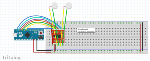
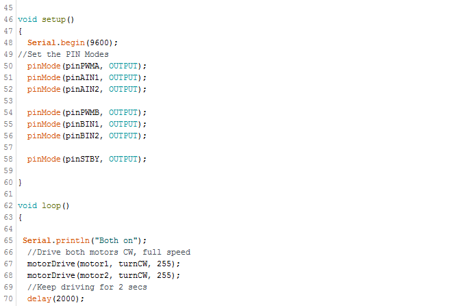
Because the 3DoT board was not ready for use by the PDR Demonstration, the base of a store bought hexbug was used with an Arduino Uno and an Adafruit Motor Shield in order to demonstrate the control of the robot with the Arxterra App. The first modification to the Arxrobot Firmware included changes to the pin and command definitions in the pinouts_robot.h file, including the header files needed for the Adafruit Motor Shield, and the creation of functions needed to control the motors and the movement of the robot.

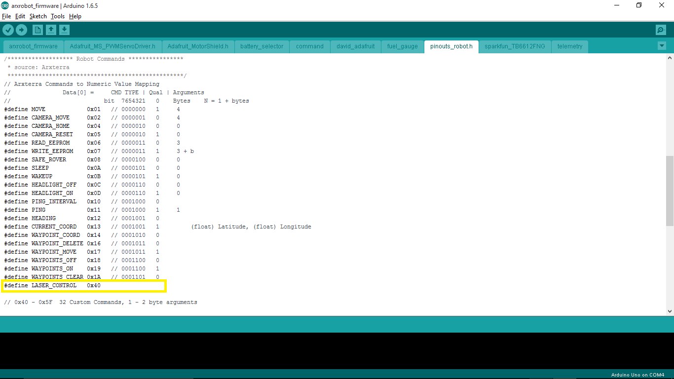
Changes to the pinouts_robot.h file

There was only one change to the pinouts_robot.h file, which was the addition of one custom command definition. This is the LASER_CONTROL command that is meant to demonstrate the control of our tagging system.pinouts change 1

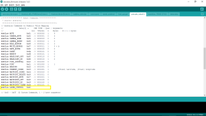
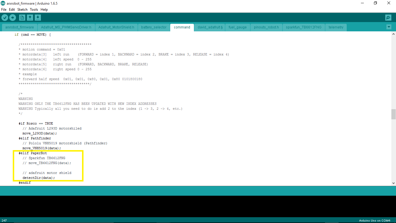
Changes to the command handler function

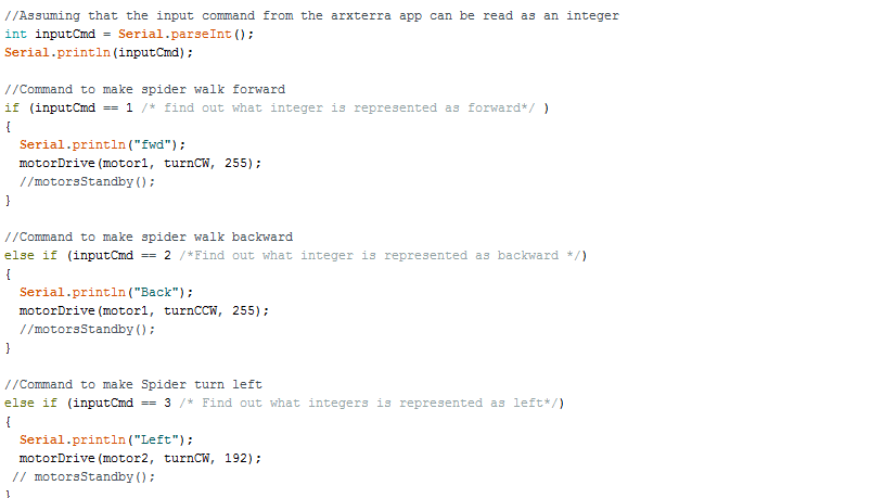
The first change to the command handler function involves changing which function is called when the move command is sent from the Arxterra App. Instead of calling the move_TB6612FNG() function, it now calls our detectDir() function.

The second change is to add the new custom command for LASER_CONTROL. A new elif block is added to execute the correct function when the custom command is sent.command change 2
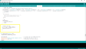
Functions to control motors and movement of the robot

Our Electronics and Control Engineer helped me create these functions by showing how to control the motors using the Adafruit Motor Shield. The detectDir() function interprets the move command sent from the Arxterra App to determine the direction the user wants the robot to move. From there, it will call the corresponding function that will move the motors. For example, if the direction is forward, the move_camf() function will be called and that function will cause the camMotor to start. The laser_status() function is for demonstrating the use of a custom command to control our laser/tagging system by turning an LED on or off.


void adafruitinit(){

 pinMode(10, OUTPUT); // Sets pin A10 as an output

}

void detectDir(uint8_t * motordata){

 // Create the motor shield object with the default I2C address

 Adafruit_MotorShield AFMS = Adafruit_MotorShield();

 Adafruit_DCMotor *headMotor = AFMS.getMotor(1);

 Adafruit_DCMotor *camMotor = AFMS.getMotor(2);

 AFMS.begin();  // create with the default frequency 1.6KHz

 uint8_t headdir = motordata[3];

 uint8_t camdir = motordata[5];

 if (headdir == 1 && camdir == 1){ // forward

  move_camf(camMotor, motordata[6]);

 }

 if (headdir == 1 && camdir == 2){ // right

move_headr(headMotor, motordata[4]);

 }

 if (headdir == 2 && camdir == 1){ // left

move_headl(headMotor, motordata[4]);

 }

 if (headdir== 2 && camdir == 2){   // backwards

move_camb(camMotor, motordata[6]);

 }

 if (headdir == 3 && camdir == 3){ // Brake

motor_brake();

 }

 if (headdir == 4 && camdir == 4){ // Release

headMotor -> run(RELEASE);

camMotor -> run(RELEASE);

 }

}

void motor_brake(){

}

void move_camf(Adafruit_DCMotor *camMotor, byte pwm){

 camMotor -> setSpeed(pwm);

 camMotor -> run(FORWARD);

}

void move_camb(Adafruit_DCMotor *camMotor, byte pwm){

 camMotor -> setSpeed(pwm);

 camMotor -> run(BACKWARD);

}

void move_headr(Adafruit_DCMotor *headMotor, byte pwm){

 headMotor -> setSpeed(pwm);

 headMotor -> run(FORWARD);

}

void move_headl(Adafruit_DCMotor *headMotor, byte pwm){

 headMotor -> setSpeed(pwm);

 headMotor -> run(BACKWARD);

}

void laserStatus(byte stat){

 if (stat == 1){

digitalWrite(10, HIGH);

 }

 if (stat == 0){

digitalWrite(10, LOW);

 }

}

Second Modification of Arxrobot Firmware

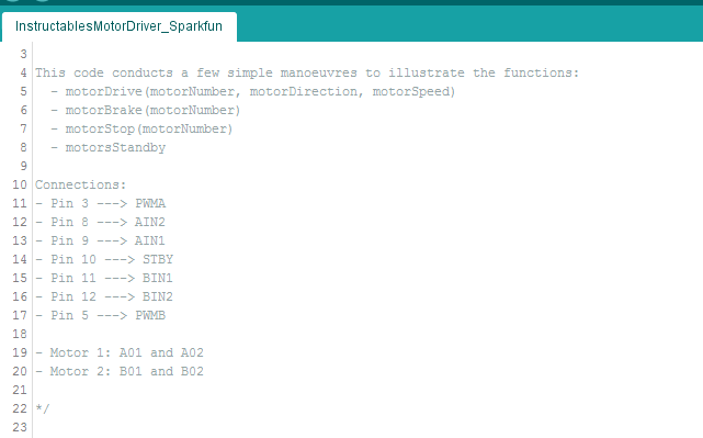
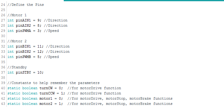
After the PDR Demonstrations, we were able to obtain the Sparkfun TB6612FNG Dual Motor Driver that is used on the 3DoT board and made the modifications to the Arxrobot Firmware to use this hardware instead. The changes made include removing the header files for the Adafruit Motor Shield, changing the functions used to control the motors, and modifying the functions in the sparkfun_TB6612FNG file. There were also a few additional definitions that were added to the pinouts_robot.h file.


Additions to the pinouts_robot.h file

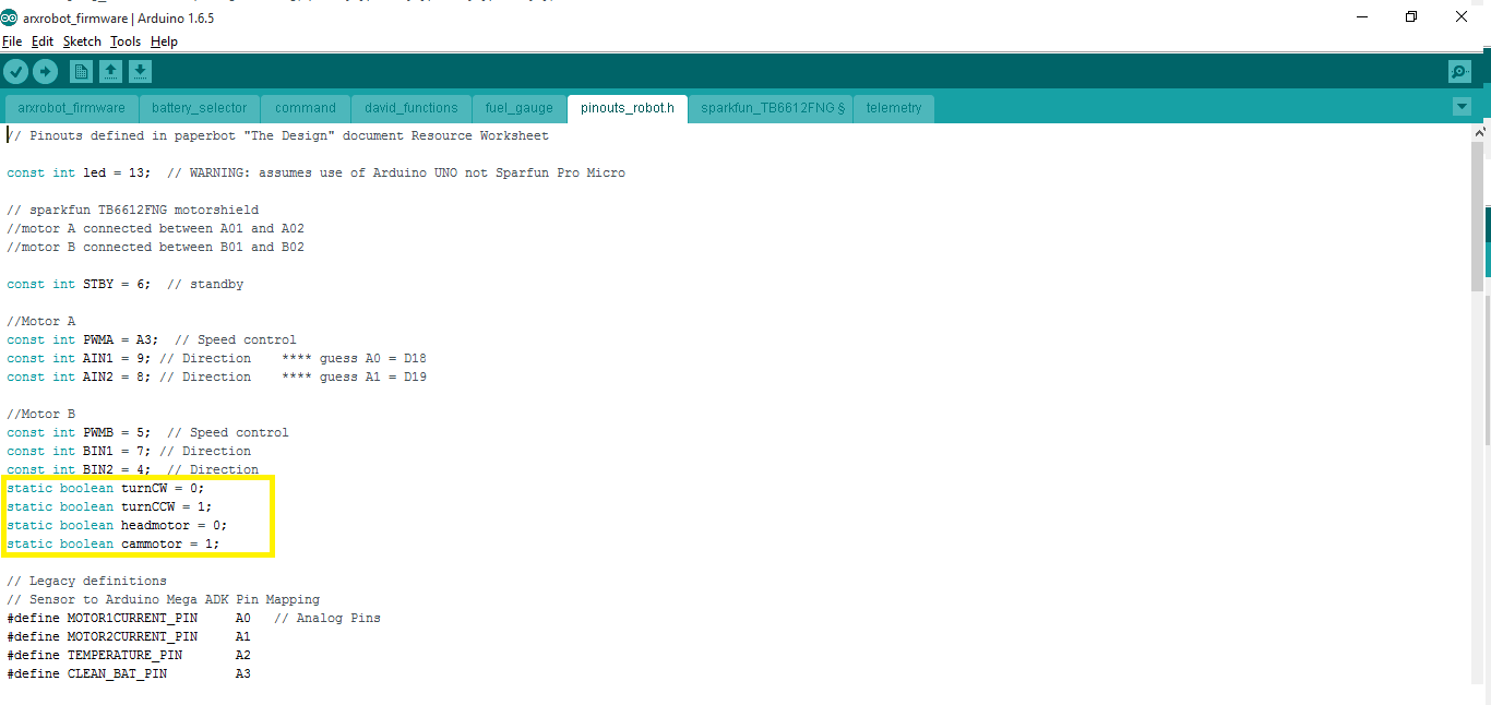
Definitions for which motor and which direction were added to the pinouts_robot.h file.pinouts change 2

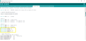
Changes to functions to control motors

The main changes to the detectDir() function are that they use the modified functions from the sparkfun_TB6612FNG file.


void detectDir(uint8_t * motordata){

 uint8_t headdir = motordata[3];

 uint8_t camdir = motordata[5];

 if (headdir == 1 && camdir == 1){ // forward button pressed – move cams motor forward

move_TB6612FNG(cammotor, turnCW, motordata[6]);

 }

 if (headdir == 1 && camdir == 2){ // right button pressed – move head motor right

move_TB6612FNG(headmotor, turnCCW, motordata[4]);

 }

 if (headdir == 2 && camdir == 1){ // left button pressed – move head motor left

move_TB6612FNG(headmotor, turnCW, motordata[4]);

 }

 if (headdir== 2 && camdir == 2){   // backwards button pressed – move cams motor backwards

move_TB6612FNG(cammotor, turnCCW, motordata[6]);

 }

 if (headdir == 3 && camdir == 3){ // Brake

brake_TB6612FNG(headmotor);

brake_TB6612FNG(cammotor);

 }

 if (headdir == 4 && camdir == 4){ // Release

release_TB6612FNG(headmotor);

release_TB6612FNG(cammotor);

 }

}

Here is the updated code for the sparkfun_TB6612FNG file.

void setup_TB6612FNG(){

 pinMode(STBY, OUTPUT);


 pinMode(PWMA, OUTPUT);  // motor A

 pinMode(AIN1, OUTPUT);

 pinMode(AIN2, OUTPUT);


 pinMode(PWMB, OUTPUT);  // motor B

 pinMode(BIN1, OUTPUT);

 pinMode(BIN2, OUTPUT);

 brake_TB6612FNG(0);    // brake

 brake_TB6612FNG(1);  

}

void brake_TB6612FNG(boolean motorNumber)     // initialize or stop TB6612FNG

{

 /* This stops the specified motor by setting both IN pins to HIGH */

 if (motorNumber == headmotor) {

digitalWrite(AIN1, HIGH);

digitalWrite(AIN2, HIGH);

 }

 else

 {

digitalWrite(BIN1, HIGH);

digitalWrite(BIN2, HIGH);

 }

  digitalWrite(STBY, HIGH);

}

void safeRover()

{

 digitalWrite(STBY, HIGH);  // TB6612FNG disabled (high impedance)

}

void move_TB6612FNG(boolean motorNumber, boolean motorDirection, int motorSpeed)

{

 /* This Drives a specified motor, in a specific direction, at a specified speed:

– motorNumber: motor1 or motor2 —> Motor 1 or Motor 2

– motorDirection: turnCW or turnCCW —> clockwise or counter-clockwise

– motorSpeed: 0 to 255 —> 0 = stop / 255 = fast */

 boolean pinIn1;  //Relates to AIN1 or BIN1 (depending on the motor number specified)

 //Specify the Direction to turn the motor

 //Clockwise: AIN1/BIN1 = HIGH and AIN2/BIN2 = LOW

 //Counter-Clockwise: AIN1/BIN1 = LOW and AIN2/BIN2 = HIGH

 if (motorDirection == turnCW)

pinIn1 = HIGH;

 else

pinIn1 = LOW;


//Select the motor to turn, and set the direction and the speed

 if(motorNumber == headmotor)

 {

digitalWrite(AIN1, pinIn1);

digitalWrite(AIN2, !pinIn1);  //This is the opposite of the AIN1

analogWrite(PWMA, motorSpeed);

 }

 else

 {

digitalWrite(BIN1, pinIn1);

digitalWrite(BIN2, !pinIn1);  //This is the opposite of the BIN1

analogWrite(PWMB, motorSpeed);

 }

 //Finally , make sure STBY is disabled – pull it HIGH

 digitalWrite(STBY, HIGH);

}

void release_TB6612FNG(boolean motorNumber){

 if (motorNumber == headmotor) {

digitalWrite(AIN1, LOW);

digitalWrite(AIN2, LOW);

 }

 else

 {

digitalWrite(BIN1, LOW);

digitalWrite(BIN2, LOW);

 }

 digitalWrite(STBY, HIGH);

}

Final Modifications

Due to several changes with the design of the 3DoT David, there were modifications to the functions that control the motors and the tagging system. With the new movement system design, both motors will need to be controlled at the same time in order to move because each motor is driving one set of three legs. Additionally, the smoothest movement of the legs required the PWM value to be set to the maximum of 255. If it was any less, the motion of the 3DoT David would look very slow and feel weird. Because of the way the ArxRobot App is set up, the user has to press and hold the direction button to increase the speed of the motors to move in that direction. The code was changed so that the PWM value would be a constant 255 and that the leg movements would be fluid.

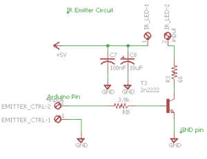
For the emitter part of the tagging system, it was decided that the IR emitter will be on whenever the 3DoT David is moving and is off the rest of the time. This is because the ArxRobot App can only send one command at a time and the alternative method of controlling the IR emitter would be using a slider on the app to turn it on or off. Implementing this in the code was easily done by incorporating the command into section of the commandHandler function that executed the move commands.

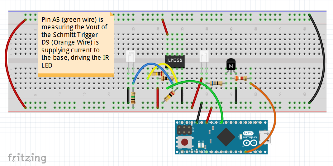
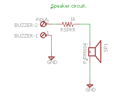
For the detector part of the tagging system, code was added to the main loop to check the output of the IR detector and if the 3DoT David should be disabled. The code is executed after the commandHandler function is called and checks if the robot has been tagged. If so, a counter would be incremented and if that counter reaches three, the robot will be disabled. When hit, the speaker will make a sound and the robot will not check for tags for 5 seconds. When the robot is disabled, it will not respond to any commands for 10 seconds and play a short song to indicate this change. All of this is done by using a flag variable to keep track of whether or not a tag has occurred. The flag will be cleared after 5 seconds have passed. When this has happened three times, the code will enter a loop that keeps it from responding to commands for 10 seconds.

Additionally, all of the extraneous code that was a part of the latest version of the arxterra firmware was removed. This includes all of the telemetry and sensor definitions that were left over from older projects that are not being used for the 3DoT David. All of the code used for debugging and testing were also removed or commented out to make sure additional processing time was not being used up.


Conclusion:

This blog post explains the process of the development of the Arxterra firmware code. It covers all of the changes done to prepare the demonstrations for the PDR and CDR.

Sources:

  1. https://github.com/arxterra/arxrobot-firmware/releases

Spring 2016: 3DoT Spider-Bot Alternative Printing for Small Parts.


BY:
Andrew Saprid ( manufacturing engineer)

After building the main parts of the 3Dot David in Solidworks, they were too small to 3D print. For the moment, it is the main problem for building and assembling the model. The picture below shows the quality of the 3D printed parts compared to the original parts. Because of the low quality of the printing, alternative methods were researched.

compare

 CNC Machine

CNC machining is a process used in manufacturing that involves the use of computers to control machine tools. CNC stands for computer numerical control. With the computer, it can control exact positioning and velocity from a computer program that customizes an object.

A 2D or 3D drawing is created from a CAD program and then a code is created that the CNC machine will understand. The process is more precise than manual machining, and can be repeated exactly the same manner.  

Screen Shot 2016-03-11 at 11.39.22 AMScreen Shot 2016-03-11 at 11.39.51 AM


The shopbot product on their site is a tool that precisely cuts, carves, and drills any machinery material. The figure below indicates a x and y axis for cutting material in either the x or y directions.

Screen Shot 2016-03-11 at 11.40.23 AM


Advantages Disadvantages
Printing small parts will provide exact replica of the drawing made from CAD/CAM program. If not proficient with CAD/CAM, then it will take 2 weeks to learn, which will take longer to learn the g code. It will take time and patience.
Fast Production Need to buy materials, which could increase the cost

Laser-cutting machine

Screen Shot 2016-03-11 at 11.41.00 AM
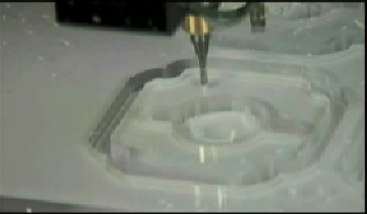
Laser-cutting will cut designs to create in most graphic software programs. Instead of laser printing paper, the machine will fire C02 laser beam that will cut through the material.

  • The C02 laser provides 30 – 120 watts of power
  • Engraving materials: wood, acrylic, glass, leather, corian, fabric, coated metals, anodized aluminum, stone, marble, ceramics, mylar, etc.
  • Cutting materials: wood, acrylic, plastic, delrin, cloth, leather, melamine, paper, rubber, veneer, cork, etc.

The Advantages of C02 Laser Cutting

  • The laser creates a beam of light that is used to cut through the material.
  • For thinner materials, all Epilog laser systems include an integrated vacuum table to hold down papers, fabric, and thin plastics as it cuts through the material.
  • It is very precise, following the design
  • Cut several patterns from the same piece of material.
  • Can be printed to the laser from variety of programs that include CorelDRAW, AutoCAD, and Adobe software

Molding and Casting

Although all are parts shall be 3D printed, this is the last resort, if 3D printing cannot print small parts.

One of the first steps is to design a mold in Solidworks to produce the parts.Screen Shot 2016-03-11 at 11.41.30 AM

When making a part, there should be a way for any air in the mold to be pushed out. This shows the flow of resin.Screen Shot 2016-03-11 at 11.41.52 AM

When casting the parts, according to the blogger, his favorite resin supplier is Smooth-On. It is very strong and flows wells into tiny parts. The cost is $27. The materials will be enough to make hundreds of the parts.Screen Shot 2016-03-11 at 11.42.27 AM

When making the perfect part, it is put inside the pressure pot because of the air bubbles the resin produces in the part. It is pressurized to 60 PSI using an air compressor, which eliminates air bubbles.

This is the last resort if any of the methods of printing small parts is not working. The reason this is the last resort is because COST is the issue. But the advantage of molding will make lives easier when replicating a part, making production faster.

Here are the materials he used:

-Solidworks

-MeshCAM CAM Software

– Delrin Sheets for the molds $6.84-$878.56 on Amazon

-Pipettes $2.98-$15.73 on Amazon

-Smooth-On task 3 Resin $26.41 on Amazon

-Smooth-on 200 Release Agent $13.20 on Amzon

-Smooth-On Pressure Pot

Stereolithography
Screen Shot 2016-03-11 at 11.56.12 AM

This is a technique for creating 3D objects, in which a computer-controlled moving laser beam is used to build up the required structure, layer by layer from a liquid polymer that hardens on contact with laser light.

Advantages Disadvantages
Parts can be shortly Can be expensive depending on which company service it provides
Creates smoother surfaces Companies have charged $30/hour
Smoother surfaces mean high level design detail and will be accurate SLA machine equipment can cost between $100,000 and $400,000
Size doesn’t have to be an issue Simple small finished prototype starts at $100
have lots of finish options

Companies that offer services for Stereolithography:

  • Quickparts
  • Ponuko
  • Shapeways
  • 3D
  • Scicon Technologies


References:

CNC Machine

http://www.thomasnet.com/about/cnc-machining-45330503.html

http://www.datron.com/Small_Part_Machining.htm

http://www.shopbottools.com/mproducts/whatscnc.htm

http://blog.cnccookbook.com/2012/02/22/10-things-beginning-cnc-milling-machine-users-need-to-succeed/

Laser Cutting Machine

https://www.epiloglaser.com/laser-cutting/laser-cutting.htm

Molding and Casting

http://www.machinistblog.com/casting-small-parts/

Stereolithography/SLA printing

http://www.intechrp.com/advantages-of-stereolithography/

http://intermag-modelex.com/advantages-and-disadvantages-of-laser-stereolithography/

http://www.designboom.com/technology/low-cost-stereolithography-3d-printer-by-formlabs/

http://www.cs.cmu.edu/~rapidproto/students.02/sstille/project2/sla.html

http://honeybuild.com/guides/stereolithography

http://scicontech.com


Spring 2016: 3DoT Spider-Bot IR Transmitter and Receiver Research

By: Christopher Hirunthanakorn (Missions, Systems and Test Engineer)

PIR diagram

Introduction:

In order to determine which optical transmitter and detector would be the best solution for implementing the game of tag between the 3DoT David and 3DoT Goliath,, the following research on IR transmitters and detectors was done. It started with learning about the various types of transmitter and detector systems that are available such as pre-made transmitters and passive infrared sensors (PIR sensor). From there, specific characteristics were researched such as range, sensitivity, power consumption, and size. Afterwards, the pros and cons of using a basic IR transmitter and detector are listed to be used for discussion.

Related Requirement:

Because this research was done before the type of tagging system to be used was decided on by both teams, this is the most relevant requirement.

  • The 3DoT David shall use an infrared LED emitter and infrared detector for the tagging system in the game of tag.

Types of IR systems:

The various types of transmitter and detector systems can be broken down into three major groups, which are the basic systems, data transmission systems, and the motion detection systems. The basic systems are composed of just an infrared emitter and an infrared detector. The emitter is typically an IR LED that emits light in the 850 nm to 950 nm range(1). The detector is usually a photosensitive transistor that conducts current when IR light is detected. Data transmission systems are the IR transmitters and receivers that are typically found in remote controls. They are used to send data and are more expensive than the basic systems because they are pre-made circuit boards. They have better range and sensitivity than the basic systems(2). Unfortunately, they are not suited for the game of tag because those features are beyond the scope of the project. The final type of IR transmitter and detector systems are the PIR sensors. They are typically used in motion detection applications and passively detect changes in reflected IR waves(3). The PIR sensor would have been the most promising solution except for the issue with false positive results when the robot moves or turns. Once this was done, more detailed research was performed on the basic system of IR transmitters and detectors.

After additional research, more information on the range, sensitivity, and ways to improve those characteristics was found. The normal range of the IR transmitter is two to four feet when it is supplied with the rated current. It is possible to improve the range of the transmitter by amplifying the current above the rated value as mentioned in several forum posts(4). It requires building a small circuit with a transistor to provide the necessary current. As for the sensitivity of the IR detector, some types have a large viewing angle. This means that the detector has a wide field of vision for detecting any infrared light. The large viewing angle could cause issues for the game of tag since it is possible for the detector to trigger when the transmitter of the other robot is not pointed in the right direction to hit the detector. After searching the internet, two possible solutions to issue were found. One solution involves picking an IR transmitter with a narrow viewing angle and utilizing a collimator to decrease the spread of the infrared light(5). It will make sure the infrared light is directed in the desired direction and improves the range of the transmitter(6). The other solution is to create an enclosure around the detector so that it will narrow down the viewing angle and modify the sensitivity to the level that suits the game of tag.
IR range pic

Conclusion:

When considering the use of an IR transmitter and detector for the tagging system, the best solution was the IR emitter and detector combination. Our robot needed the sensitivity and controllable intensity that this combination provides because the range of the tagging system must be customizable. The other IR systems did not provide this amount of control and were eliminated. We are currently considering the solution that involves using a lens to focus the intensity of the IR emitter.

Work cited:

  1. http://www.futureelectronics.com/en/optoelectronics/infrared-emitters.aspx
  2. http://www.seeedstudio.com/wiki/Grove_-_Infrared_Emitter
  3. https://learn.adafruit.com/pir-passive-infrared-proximity-motion-sensor/how-pirs-work
  4. http://www.instructables.com/answers/How-to-get-the-best-range-out-of-an-IR-LED/
  5. http://electronics.stackexchange.com/questions/170993/can-an-ir-transmitter-be-focused
  6. http://forum.arduino.cc/index.php?topic=157622.0

Spring 2016 AdBot Preliminary Design Documentation & Plan

AdBot is a rover that will climb stairs.

Preliminary Design Document

By Dang Le, Project Manager, and Don Tran, System Engineer

  • Dang Le (Project Manager)
  • Don Tran (System Engineer)
  • Muhammad Ali Siddiqui (Electronic Engineer)
  • Muhammad Maqbool (Manufacturing Engineer)

Program Objective/Mission Profile
The customer wants a stair climbing robot to advertise his company in front of a building, and wants wireless steering using the Arxterra app for smartphones. We will give the customer Bluetooth. We will design the rover by May 14, 2016 around a $400 starting budget. The customer wants to use any parts available in the Electrical Engineering department or from the previous semester’s RoSco. We will document our thinking across the semester. The mission profile will be a test course consisting of the 9 steps in front of the USU building, then the concrete path clockwise leading down some inclines back to the bottom of the stairs. The images below show the bird’s eye view, front, and side of the test course.

AdBotRoute FrontUSU LeftUSU

Project Program Requirements

Level 1 Requirements
1. The project involving making AdBot and the blog posts shall be completed by 5/13/2016, which is last day of this 400D course:
2. The budget shall be $250, which is an estimate of most parts needed.
3. AdBot shall follow CSULB regulations for activities and for advertising.

4. AdBot shall travel 160 feet on concrete. This distance is the length of the test course counting inclines and stairs.
5. AdBot shall travel up 9 or more steps. The stairs in front of the University Student Union building consists of 9 4.3″x16″ steps.
6. AdBot shall use the Arxterra application for smartphones.
7. AdBot shall protect its hardware from rainfall and from a 50 psi water sprinkler.
8. The rover shall have at least one 3D-printed wheel, track, or parts.

ADVERTISING/PUBLICIZING EVENTS
All programs must be properly scheduled, confirmed and cleared prior to any notice or advertising of the event. All advertisements must include the sponsoring organization, name of program, date, time, location and contact information. Advertising in the USU of events hosted in the University Student Union and Soroptimist House require posting approval by ASI Communications, USU-235.

Level 2 Requirements

Level 1 requirements below are the same as the ones above, but restated.

Mission

L1: The primary focus of AdBot’s design is to make sure that it shall be able to travel up and down stairs in order for it to complete the test course that the president and division manager laid out.

  • The front of the University Student Union building consists of nine 4.3″x16″ steps. AdBot shall be able to travel up and down at this 15-degree incline.
  • AdBot shall be operational approximately 30′ from the smartphone-controller when no obstacles are obstructing. HC-06 Bluetooth receiver is rated for approximately 30 feet.
  • AdBot shall lift its front end at least 4.3 inches with the use of two servos.
  • The time to complete one circle of the test course shall be approximately sixteen minutes, at this point. This is time does not consider longer times going up stairs. For now, the following calculations are guessed for the 64 rpm free run speed, 800 mA stall current motors.

Budget

The budget shall maintain a low cost. The cost shall stay below $216 to $366. RoSco last had problems with 3D-printing driving up their costs from $216 to $366, and some cost was having to even pay for printer errors and problematic parts.

  • RoSco’s four motors and six servos uses 3 to 6 V input. The current 7.2 V battery is capable of driving those parts. It shall be used while prototyping AdBot.
  • It is important for AdBot that the amount of power it uses shall allow it to run for the proper length of time. The best case is it can travel the test course laid out one or more times. The current motors have a free run speed of 64 rpm and a stall current of 800 mA. When torque is calculated, then one can find the exact total power consumption. http://www.me.mtu.edu/~wjendres/ProductRealization1Course/DC_Motor_Calculations.pdf

AdBot shall have one or more 3D printed wheel, tracks, or parts. The manufacturing division within the company focuses on 3D modeling and 3D printing.

  • AdBot shall use ABS plastic against other types. When printed correctly, this material is durable. One ABS plastic track on RoSco can withstand 150 pounds placed upon it.
  • AdBot shall keep its tracks from coming off while AdBot is moving. The current treads are approximately 12 inches when loose. AdBot’s design will consider stretching the treads or shielding it around the wheels. The treads may also be cut and melted to a shorter size.

Size

AdBot shall build upon RoSco’s design while conforming to CSULB regulations for activities and for advertising.

  • AdBot shall fix the loose tracks that was the main problem that RoSco had.
  • RoSco protected its components from direct rainfall, such has having a waterproof chassis and motors inside its legs, but the cover for the chassis did not close its gap fully. Therefore, AdBot shall also protect its hardware from both rainfall and puddles, for as long as its mission duration. One solution would be using weatherstrip tape as one can cut it to exact dimensions.
  • AdBot shall remain under 3 feet. The regulations for activities and advertising, in short, issues that signs must not exceed 3×3 feet. The height of the rover and the stake together will be designed under this height.

Feature

AdBot shall require the use of the Arxterra application on smartphones and the Arxterra Control Panel on the internet browser to control it.

  • Arxterra has a setting called community where controls are on the Control Panel at http://cp.arxterra.com/# and the camera on the smartphone turns on for visible capability. AdBot shall be able to move the camera around separate from its main body. The solution is to have a pan, tilt system, because the firmware code for Arduino has a pan and tilt function.
  • The smartphone shall have internet access. Arxterra’s Control Panel does not connect to the phone when the phone is not on a wireless internet network.

Timing

The project involving making AdBot and the blog posts shall be completed by 5/13/2016, which is last day of this 400D course.

Design Innovation
AdBot’s design will take to consideration a maximum load weight placed upon the tracks or the chassis-to-track connections in order to keep the tracks aligned. AdBot may or may not have a pan and tilt system holding a picket sign. The priority is to make AdBot work and have enough power to complete the mission profile.

Systems Design
System Design Diagram
AdBot’s tracks shall have up to 1 motor each. It will have free spinning wheels on opposite ends of the tracks. Parts from the old PCB will be reused. More blocks will be added to the systems design as we learn more about the project.

Product Breakdown Structure
AdBot PCB
The PBS lists the software and hardware needed for a running prototype.

Manufacturing and Design

By Muhammad Maqbool, Manufacturing Engineer

The big tracks on each side of the robot consist of a total of four wheels, two in the back connected together with a steel rod and two in the front connected with another steel rod. We are thinking about using any spare leather belt so we don’t go out and buy it. on the belt we are thinking to layering wood patches so our track can have a firm grip which we will obtain through popsicle sticks. The wheels will be rotating at all times hence rotating the belt with it. As you can see the big tracks are attached to two small tracks called legs. The legs are attached to the gear system hence moving up while climbing up the stairs. The legs consist of four wheels total, two on each side.

For the wheels we will be needing reliable 3D printer, if not then we will be using the wheels from the old rosco as they are in good condition. Our main goal is to cut the cost as much as we can when it comes to the designing. So we can save money and buy some heavy duty motors and battery that can last longer once our robot performing its task.

The chassis and tracks shall be constructed after the dimensions are finalized in SolidWorks.

We shall use a 3D printer to print our desired components. ABS plastic will used to cut the cost to lower than $90.

Muhammad Maqbool shall obstain good 3D prints with the desired dimensions.

He will use Eagle CAD to design the PCB. The PCB will then be tested.

Small tracks on the AdBot will help it climb up, as it will be facing up while climbing up the stairs.

These are 3D models of AdBot:

4 5 6 7
2 1

Electronic and Test

By Muhammad Ali Siddiqui, Electronic Engineer

System Interface Matrix

Pinout1
Pinout2

The interface diagram shows the connections of the Bluetooth sensor, motor control board, and motors.

  1. Work with systems engineer to create interface definitions and to create functions/subroutines for microphone, speake
  2. r, camera, and graphics display unit.
  3. Create fritzing diagram from the interface matrix.
  4. Create fritzing diagram for custom servo controller board.
  5. Create pcb layout for the custom servo controller board.
  6. Work with systems engineer to determine the type of battery to be used.
  7. Perform tests and run simulations to determine suitability of sensors being used.
  8. Consult with the division manager to determine audio and video encoding to be used for the AdBot.
  9. Shall be testing battery the to determine if it is capable to complete task 100% with 55 to 65% of battery consumption.

Unique Task Descriptions

By Muhammad Maqbool, Manufacturing Engineer

1. Create 3D models using solid works and obtain good 3D prints using 3D printer. (5 weeks)
2. Manufacture PCB design using EagleCAD. (2 weeks)
3. Run simulation of AdBot in solidworks. (3 weeks)
4. Research which material is best for the Wheels, the body and the arms of AdBot. (3 weeks)

Preliminary Plan Document

By Dang Le, Project Manager

The AdBot diagram of work breakdown structure below shows individual responsibility during the project. Don is responsible for Mass report, Power report, Arduino coding, and verification test plan and report.
Muhammad Ali Siddiqui is in charge of PCB design, build breadboard, and coding for the motors, servo, Bluetooth, camera, audio, etc.
Muhammad Maqbool is responsible for 3D modeling and solid works design for chassis, wheels, and track.
Dang Le is responsible for project update, photo/video editing and order parts. He will take some work load from manufacturing like soldering components on PCB, cable tree wiring, and assembly AdBot.

Work Breakdown Structure

WBS-72dpi

This work breakdown structure exists to provide task coordination in this project team. Each block indicates the responsibility of only one engineer designated it.

Project Schedule

By Dang Le, Project Manager

We have been working on the prototype of the AdBot. Muhammad and Don was testing the motor, servo, and Bluetooth device. In the mean time, Muhammad Maqbool was designing the wheels and chassis. We will test our prototype when everything ready and fully assembled. Using the Projectlibre tool, we should see our task move along with our schedule as we planned or not. This schedule allowed us to focus closely on each stage as we move on until the completion date. This is our final schedule in planning to complete our project.

Top level Schedule

projectschedule1-72dpi

projectschedule2-72dpi

The schedule begins on Feb-12 and ends on May-13. Both planned and actual remaining time will be measured in days.

System/Subsystem Level Tasks

System-subsystem-72dpi

The system and subsystem level have defined by our work breakdown structure

Burn Down and Project Percent Completion

BurnDown-72dpi

The burn down chart is measured by weekly progress.

System Resource Reports: Power Report, Mass Report, and Cost Report

Power Report

Power Report MAS

The projected values on the power report are all estimates based on research on components. Since the maximum current allowed was undefined, a reasonable value was chosen for the project allocation. By the end of this week, measured free and stall current for servos and motors will be added. This requires using an Arduino, spring scale torque-measurer, and more.

Mass Report

Mass Report MAS

The projected values on the mass report are estimates based on research on components, and since the upper weight limit was undefined, the projected weight seems reasonable. By the end of this week, actual weights will be included.

The mass report came about this way:
1. Label all the parts in the AdBot blueprint/mockup drawing or check the PBS.2. Search available components from retailers/Sparkfun.
(Parts may change depending on torque decisions, etc.)
3. Search for model datasheet PDF files on Google to find component masses.
4. Estimate the mass for 3D-printed parts.

Project Cost Estimate

Cost Report

The cost report from 2/26 is replaced with an alternate cost estimate made earlier by Don Tran. A better table will replace this in a few days once midterms are completed. The table currently excludes four motors and four servos from RoSco. A prototype rover is being assembled and more idea about the handling of mass and load by the current motors will be found out.

Spring 2016: 3DoT Spider-Bot Preliminary Design Document.

By: Omar Mouline (Project Manager), Christopher Hirunthanakorn (Missions, Systems and Test Engineer), Kent Hayes (Electronics and Control Engineer), Andrew Saprid (Manufacturing and Design Engineer)

Table of Contents

The 3DoT Spider team:

Omar Mouline                                (Project Manager)

Christopher Hirunthanakorn          (Missions, Systems and Test Engineer)

Kent Hayes                                    (Electronics and Control Engineer)

Andrew Saprid                               (Manufacturing and Design Engineer)


Preliminary Design Document.

Objective:

The customer wants a feasibility demonstration of a 3DoT Board, from ArxterraTM, for a low cost, DIY project. The idea behind the 3D of Things (3DoT) is for the DIY community to construct small-scale and quick-production robots. The project must be able to perform an interactive game with other projects. The overall result must be professionally presentable (as a promotional video) for The College of Electrical Engineering and ArxterraTM.

Requirements:

Program requirement:

  1. As a senior design project for Spring 2016, the project shall be completed by May 13th, 2016 Monday, May 9, 2016 2:45PM – 4:45PM (Final day) on the linoleum floor of ECS315 at CSULB.http://web.csulb.edu/depts/enrollment/registration/final_exam/spring_chart.html
  2. As a senior design project for Spring 2016, Documentation of the 3Dot Spider-bot shall be completed by the 25th of April http://web.csulb.edu/~hill/ee400d/Syllabus.pdf

Project Requirement:

  1. The project shall be Cam-based robot that demonstrates the capability of the new 3DoT micro-controller for DIY hobbyists.
  2. The 3DoT Spider project shall be a low cost project with a budget that does not exceed $79.95, which include the cost for the 3D printing material, PCB, battery, and other components.
  3. To document the difference between development cost and final product cost, the 3DoT spider project must create a Project Budget and a Product Budget
  4. For a Quick Production, the project has been restricted to six hours of total printing time with a 2 hours limit for each single print.
  5. The competing robots shall use an on-board optical transmitter and receiving system to simulate a game of tag.
  6. The orientation of the transmitter and sensors shall be parallel to ground. Since both teams are still designing the robots, the height of the sensors and transmitters is temporary set to 3 inches above ground until both teams finalize this requirement .

System requirements:

  1. The 3DoT Spider shall utilize the Bluetooth module on the 3DoT board in order to receive commands from the Arxterra Control Panel (via the Android Application).
  2. The 3DoT Spider shall use a single 3.7V Lithium-ion battery or a 3.7V Lithium-ion Polymer (LIPO) battery to power the 3DoT board.
  3. The 3DoT Spider shall operate for three rounds of “Tag”. One round of “Tag” ends when a robot has been “hit” three times and is disabled. This may last for 10 to 15 minutes.
  4. The 3DoT Spider shall use a micro servo for head rotation and a motor for the Cam-based  walking movements of the robot.
  5. The 3DoT Spider shall use an on-board optical transmitter and receiving system to simulate a game of “Tag”.
    1. The type of optical transmitter and receiving system is still being researched.
  6. The 3DoT Spider shall be disabled after being tagged three times to signify the end of the “Tag” game.
  7. The 3DoT Spider shall incorporate 3D printed parts for the legs, body, or head. This follows from the level 1 requirement dictating the limit on 3D printing times.
  8. The 3DoT Spider shall include an external PCB that uses an op-amp comparator with hysteresis to perform the analog to digital conversion of the sensor inputs. This external PCB shall also provide the connections from the 3DoT microcontroller to its peripherals such as the optical transmitter, servo, and motor.

Subsystem requirements:

  1. The servo and motor shall operate in between the supply voltage of 3.7V-5.0V, be able to rotate 360 degrees continuously, and be priced reasonably in order to stay within our budget
  2. .The spider-bot shall be made of plastic light-weight material in order to save battery power and strong to hold the its weight.
  3. The laser shall be built on the head 3 inches from the surface to the top of the spider.
  4. The spider-bot shall have six legs to operate its course to battle robots.

Design innovation

Following the same process we did on our creativity presentation, we considered additional  problems where we applied the same principle to find solutions.
The two main problems we have to consider are the printing time for the parts of the robot and the limited budget. We have a proposed solution for both and they will be modified upon customer feedback. For the printing time, we will create a design for the legs and chassis that use the minimal amount of material. When it come to the cost, we will use the most cost effective components.

https://docs.google.com/presentation/d/16sMUoAAnMPPTLNCC8_uLHyztSfAgli1p8mzOXfZE3bU/edit?usp=sharing

System/Subsystem Design:

Product Breakdown Structure:

Screen Shot 2016-02-26 at 11.02.45 AM

This product breakdown structure outlines the major components of the 3DoT Spider. The 3DoT Spider can be broken down into the battery, 3DoT microcontroller, legs, and chassis. The battery will be providing power for the whole system. The 3DoT microcontroller will be controlling the motor, micro servo, optical transmitter, and sensor. The legs includes the design of the 3D printed legs and the Cam-based movement system. The chassis includes the design of the head and body of the 3DoT Spider where all of the components will be enclosed in.

Electronic System Design:

System Block Diagram:

Latest System Block Diagram

This system block diagram shows how the different components of the Spiderbot interact with each other. The android device uses the Arxterra Control Panel to send control commands through bluetooth to the bluetooth module on the 3DoT microcontroller. The 3DoT microcontroller will process those commands and send out the corresponding instructions to the motors, optical emitter, and detector. The battery provides power for the 3DoT microcontroller, which is then distributed to all other components.

Interface Definition:

Screen Shot 2016-02-26 at 1.48.26 PM

Mechanical design:

First step was to analyze the Cam-Based movement of the Hex-Bug. It was done as a power point presentation to explain to the team members:  Cam-Based Power Point Presentation

Building Parts Process:

Screen Shot 2016-02-16 at 4.40.40 PM

This is the first rough draft of the 3Dot Spider. Each leg is placed symmetrically to each other to ensure stability and be able to carry its weight. The original hexbug spider is too small for the 3Dot board to fit inside the head. The method is to resize the model given to make sure the 3Dot board fits inside the head. This is the 2nd rough draft of the initial base design of the 3Dot Spider. The new 3Dot board measurements are 3 inches in length and 2 inches in width. Adjustments were made to make sure the board fits into the base of the Spider.

Screen Shot 2016-02-29 at 4.00.19 PM

This is the base design of the 3Dot Spider-bot on SolidWorks. The base is designed to fit the PCB inside the head of the 3Dot Spider. The shape of the base design is a circle with a diameter of 4 cm from the center of the PCB to make the decrease the cost and lower printing time. This is to make sure the PCB fits inside the 3Dot Spider-bot and make it invisible from a human eye.

Screen Shot 2016-02-16 at 4.41.28 PM

This is a rough sketch of the head of the 3Dot Spider. The laser will be placed 3 inches, or approximately 7.62 cm from the surface to the top of the spider. Laser placement will be an issue because of the length of the head is 12.5 cm, but the surface is not taken into account. From the surface to of the spider to the bottom is 5.5 cm measured approximately. From our studies, the laser should be better put on the head because the head is rotating 360 degrees otherwise it will be placed between the leg of the spiders which will make it an obstacle to the spider’s walk.
Screen Shot 2016-02-29 at 4.05.18 PM

The leg design of the 3Dot Spider-bot is made from Solidworks. The length of the leg is 5.5 cm. The width of the original Hexbug Spider measures 0.8cm width on the top, 5.5cm in length, and 0.3cm width on the bottom. The reason why the leg is slanted is to ensure stability as it walks and support its weight.

Exploded View

CAM_movement_system_2

The exploded view is showing Most of the important parts for the 3DoT David which includes: Tibia, Femur, joints, and Cam based.

Unique Task descriptions:

Christopher Hirunthanakorn

  1. Perform trade-off study with 3DoT Goliath team to finalize what optical transmitter and sensor to use for the tag game. (1 week)
  2. Create Fritzing diagram for the circuitry needed for the 3DoT Spiderbot with complete wiring and pin-outs from the microcontroller. (2 weeks)
  3. Create and test custom Arxterra Control Application used on an Android device for controlling the 3DoT Spiderbot. (6 weeks)
  4. Write code for the 3DoT microcontroller to decode instructions received from the Arxterra Control Panel. (6 weeks)

Kent Hayes

  1. Consult the Goliath team’s Electronics and Control division in order to determine what type of optical transmitter and receiver is being used for the game of “tag”. (1 week)
  2. Work on simulations for servo/motor control through the arduino uno board until the new 3DoT board is shipped (2 weeks)
  3. Create a Frizting diagram from the interface matrix (2 weeks)
  4. After determining the transmitter/receiver, order the parts and conduct tests on battery life with all the components to analyze how long the battery can run with its 1000mAh rating and write a document explaining the results. (3~4weeks)
  5. Create an electrical schematic for the pcb layout using eagle CAD (2~3 weeks)
  6. Work with the systems engineer to write software subroutines and functions to read data from the optical transmitter/receiver to let the players know their bot has been tagged. (3~4 weeks)

Andrew Saprid

  1. Create a complete 3D model of the 3Dot Spider by using Solidworks. Once completed, it will be sent to 3d print shop for printing parts. (4 weeks)
  2. Run simulations and tests for the complete 3D model in Solidworks. ( 2 weeks)
  3. Perform a stress test on the leg design to determine the maximum stress level. (1 week)
  4. Research cost-efficient and resilient types of material by doing a trade-off study. The study will do a comparison of types of material that would best fit the Spider in terms of strength,  weight and price (1 week)
  5. Fabricate the PCB designed in EAGLECAD (2 weeks).

Preliminary Project Plan

Work Breakdown Structure (WBS) Chart

By Omar Mouline, Project Manager

Screen Shot 2016-02-23 at 11.32.25 PM

Project Schedule

By Omar Mouline, Project Manager

Using the Simple Robot Project Libre as a reference to organize my schedule, since The Simple  Robot Project had a well defined tasks.I also used the Project Libre tasks to create the Burn Down Chart.

Top Level Schedule

Screen Shot 2016-02-26 at 11.26.20 AM Screen Shot 2016-02-26 at 11.34.19 AM

System/Subsystem Level Tasks

new1 new2 new3

Burn Down and Project Percent Completion

Screen Shot 2016-02-23 at 4.10.01 PMThe graph below compute the competition of the project tasks. When a task is started 50% of its weight is assigned as completed. When a task is completed the remaining 50% is added to the score.


System Resource Reports

By Christopher Hirunthanakorn (Missions, Systems and Test Engineer)

Power Report

Latest power report

This power report is an initial estimation of the amount of power the 3DoT Spider will use. The values for each component were obtained from the datasheets if possible. When the datasheet did not have that information, a reasonable estimate or calculation was used instead. For example, the information on the current used for the 3DoT Board is taken from page 383 of the ATmega 32u4 datasheet (https://drive.google.com/file/d/0B9ONhnOsqgWdUjNjTGI5bExaZHc/view?usp=sharing). While it is not explicitly stated what the minimum, maximum, and average current draw are for the ATmega 32u4, a reasonable estimate was made to obtain those values.

The average current and expected power columns required some calculations in the case that it was not on the datasheet. The average current was calculated by taking the average of the minimum and maximum currents ((Minimum + Maximum)/2). The expected power was calculated by multiplying the rated voltage by the average current. For the most part, only the micro servo and 3DoT board needed this calculation.

The justification for the allocation of 2.5 watts for power is that it is a reasonable amount of power for a small robot. Assuming that most components operate at 5 volts, the total average current draw of those components would be around 800 mA. The 3DoT Spider should use less power than that even when including the total margin, which can be seen in the report.

Mass Report

Latest mass report

This mass report is an initial estimation of the total mass of the 3DoT Spider. All values are approximated except for the motor and micro servo, which are taken from their corresponding datasheets. It should be noted that the mass for the legs is the sum of all six legs. It is approximated that each leg will weigh 10 grams with a margin of + or – 3 grams. Those values were determined based on the weight of the first prototype leg. It weighed 15 grams and is much larger than the current version.

The justification for allocating 350 grams for the mass of the 3DoT Spider is that it is slightly above the total expected mass. It allows for quite a bit of contingency in the case that certain components such as the body or head frames end up being larger than expected. It is very likely that the project allocation will decrease as more accurate approximations for the 3D printed parts are obtained because the 3DoT Spider will be designed to be as small as possible.

Project Cost Estimate

By Christopher Hirunthanakorn (Missions, Systems and Test Engineer)

Cost Report

Latest Cost report

This project cost report is an initial estimation of the total cost of building the 3DoT Spider. All of the expected prices listed are rough approximations or the average price for that type of component. The customer wanted a low cost robot that would cost $79.99, however the estimated total cost is $81. The total cost may decrease once components have been finalized but it is more realistic to budget for the margins and contingencies as well. In the case the actual price includes the total margin value, it will be $108, which is already $28 over the desired cost. Therefore, we propose a project allocation of $120, which will be discussed with the customer.