Spring 2016 AdBot Critical Design Review

The Rover should travel on level area, ramp area, and stair ways during the mission test.

Critical Design Review

By Dang Le, Project Manager

  • Dang Le (Project Manager)
  • Don Tran (System Engineer)
  • Muhammad Ali Siddiqui (Electronic Engineer)
  • Muhammad Maqbool (Manufacturing Engineer)

Executive Summary

Program Objective/Mission Profile

Program Objective

The project objective is to build a rover that will simulate a flyer distributor advertising CSULB’s Eta Kappa Nu social, guest speaker, and technical events on campus. Using a single power source the rover will launch from, and return to, an HKN advertisement booth and run in a general high foot-traffic area on campus which consists of flat areas, sloping areas, and stair ways, as shown in the course map. The rover will be controlled remotely using a computer with internet connection. Negotiations of budget resulted in the rover to cost less than or equal to $250. There is to be expected 0 to 16 mph wind during the course run on May 13th (Reported in Weather Report).

Mission Profile

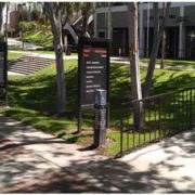
The total distance is approximated in 344fts. The perimeter of the grass is 275 ft / 84 m. The north and south sides are leveled. The east side has 9 steps. The west end is a ramp.

Mission-CDR-72dpi

The front of USU building

The Design

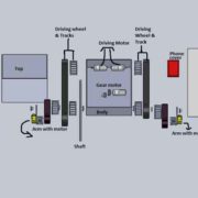
The main component in our rover design are including

  • Four drive motors (2 on the front and 2 on the back).
  • One gearbox motor (for the center).
  • Six wheels and tracks.
  • Two arms with supported by horizontal shaft and gear.
  • Pole holder for advertising and smart phone.

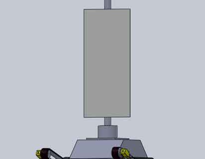
Adbotexplosive-72dpi

Project Features

  • Rover with advertising sign will be traveled up stairs and slope area in front of USU building.
  • Rover will be run and return to HKN advertisement booth in a single charge.
  • One shaft  with high torque gear box motor to support the lifting arms weight during the stair climbing.
  • Operator will be controlled remotely using Arxterra application with computer wifi connection.
  • Innovative wheels design to have a better track grip.
  • New aerodynamic body design to reduce weight and wind resistance

Custom PCB Design

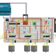
Fritzing diagram circuit with three H-bridge and I2C protocol IC to drive five motors with using Arduino and firmware coding.

CDR-Frizing-72dpi

Fritzing Diagram


Custom-PCB-72dpi

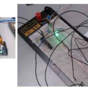
Breadboard testing transmit and received data with using H-bridge IC circuit and Arduino coding.


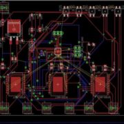
PCB layout

PCBlayout-CDR-72dpi


Hardware Design

By Muhammad Maqbool, Manufacturing Engineer

The body of our AdBot is set to be 12” x 8” x 2”. The Body is made of Aluminum. I got separate sheets of Aluminum each with a thickness of 0.125 inch and I welded them together with the help Ryland Walts. The reason for choosing Aluminum is that for our AdBot we wanted a strong body that would not get damaged if our AdBot hits the stairs or anyone try to kick it.

The body consist of two holes in the back each of a diameter of 0.16 inches, the holes provide a path for the driving motors to directly connect with the wheel. The two holes in the front of the body provides a path for the shaft to pass through and will be connected to the free moving wheels and arms.

The wheels are printed using ABS plastic. ABS plastic is the most cost effective material. Each Wheel has a diameter of 2.5 inches and a thickness of 0.7 inch. The arms of the our AdBot will be of Aluminum as wheel, the arms will be 6” x 1” with a thickness of 0.125 inch. We have two motors in the front of the arm that will be driving the front wheels at all times. I have designed the gear for the shaft and the motor myself. As the motor rotates the gear on it rotates with it hence rotating the gear on the shaft and lifting the arms. I have designed two arm holder myself that will hold the arm on the shaft at all times.

The top of our AdBot is more aerodynamic by adding curves to it so it can go fast. The top is 12” x 8” and will sit on the body and I will screw them both. I will design a pole holder that will hold our pole hence holding our sign.

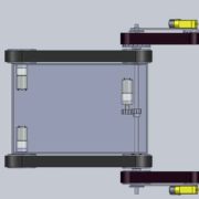
Adbot-topview-72dpi

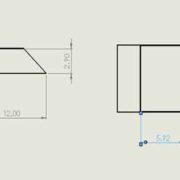
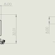
top-CDR-72dpi Demension-CDR-72dpi

Software Design

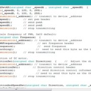
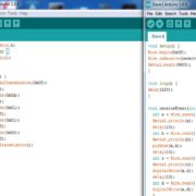
Test code for controlling motors with Arxterra Application

SW-CDR-72dpi

SW-master-Slave-CDR


Project Update

By Dang Le, Project Manager

Work Breakdown Structure (WBS)

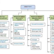
As a project manager, who created and assigned tasks for each member within the team throughout the project. A work breakdown structure (WBS) that showed each of team member who had responsible for their tasks. There could be a change during the mission task depend who has more free time and ability to take workload from other member. Here is our delegation tasks that showed in display below.

WBS-CDR-72dpi

Budget Report updated

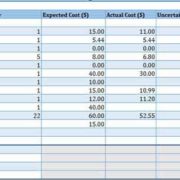
As a Project manager, I have to keep track on our budget to make sure it still within our given budget. The most expense is on prototype component and chassis. Unfortunately, our rover were bigger compare to previous semester, thus we have to look for the difference type of tracks that can support our rover during the mission test course. First, we thought we could use 6V DC motor for our rover ( these motor are free from previous semester), but now due to the rover is too heavy and may not be able to travel on stair ways and long distance, so we may replaced with 12V DC motor for final demo. Our budget report with expected cost right now without five of 12 V DC motors is $220.44.

Cost-report-CDR-72dpi


Schedule Updated

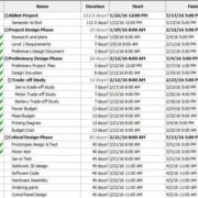
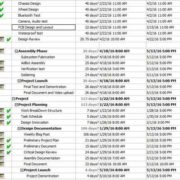
Project schedule is the software that used to create a task schedule and plan in this project for a specific date to be completed. As the project moved on, we could see which tasks we were completed or behind the schedule. The schedule showed in green check mark that indicated these tasks were completed. However, the main concern was the PCB schematic and PCB wiring layout. We have built a new schematic, which more complicated than our thought due to more parts on PCB and not enough clearance between one trace to another, thus our team member were having so much trouble when doing the layout. Furthermore, we were down by one of our team member electronic engineer. Thus, we were behind the schedule as our planned. Another issue was main tracks for our rover. The current track we have as the same last semester that was not support enough for our rover during the mission test. We are still looking for the tank track and 12 V DC motor with high torque for our AdBot.

ProjectSchedule1-CDR-72dpi ProjectSchedule2-CDR-72dpi


Status and Percent Complete

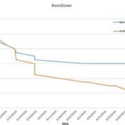
Here is the status and percent burn down  as we move along until this time. The charts showed that we were behind on software coding, PCB layout, and hardware as well.

PercentcompleteCDR-72dpi BurnDownCDR-72dpi

Project Demonstrations

click the link below to watch the AdBot demonstration

https://www.youtube.com/watch?v=CX5fDNFeUjc


Rover Field Presentation Debriefing

By Maxwell Nguyen, Project Manager

During the field presentation of the rover, spiderbot, and hexapod, all three groups were able to successfully launch their projects.  However, all three groups encountered a few similar problems that prevented the projects from completing the mission objective. 

Level 1 Requirements:

The height requirement of the rover was completed and verified.  The rover was able to move over the sprinkler as well as roll over smaller obstacles on the field.  It was able to drive over small twigs and pinecones without tipping over.  The power of the rover was sufficient to drive itself the entire course.  However, the rover was unable to complete the entire course due to connection issues.  The mirror system was able to provide the rover proper vision during the mission.  The pan and tilt in junction of the mirror are fully functional.

Troubleshooting and Issues:

We noticed that connection to Arxterra was extremely weak and limited on the field site.  This was not an issue due to lack of wifi signal.  Even though the wifi source was in range, strong, and secure, connection to Arxterra was not stable.  The rover was only able to connect to Arxterra for a few seconds before being disconnected form the website.  We believe that this was due to all three projects trying to connect to Arxterra at once.  There seemed to be no connection problems when only one robot was connected to Arxterra.  However, if multiple robots were connected to Arxterra at the same time, connection would be extremely limited.  Even then, there were other issues running with Arxterra.

The rover suffered from latency problems while running the course.  When inputting commands for the rover, there would be a rough estimate of one second delay before the rover reacts to the commands.  At times, the latency would be so great that the rover would not receive any commands at all.  This again was not due to the wifi signal to the phone or the labtop.  All components of the rover were active but was not receiving any commands through the labtop.  However, this issue only appeared several times and was not a consistent problem.

If this project is recreated, it is strongly advised to test in junction of other projects instead of individually.  By running field tests with other projects, problems with Arxterra and wifi connection can be more accurately identified and fixed.

Solutions to Wi-Fi connection issue

Members:
Vinh Khoa Ton: Biped team, Control & Image Processing
Tien Dang: Hexapod, Communication

Chau To: Hexapod, Computer systems & Software
Mevan Fernando: 3D Bio Printer, Sensors, Actuators & Powertrain
Robert Licari: Communication

Objective by Vinh Khoa Ton:

Hexapod team and Spiderbot team need to run their robots on a track field that does not support internet connection. Our team’s goal is to find a way for them to get access to the Wi-Fi connection so they could control their robots remotely using Arxterra control panel. The solution should have minimum cost. The internet connection should be stable (no disconnection or lost signal) with enough bandwidth for at least two mobile phones and two laptops, and the range of Wi-Fi is enough to cover the track field.

Some considered solutions

Wi-Fi Antenna by Tien Dang

http://arxterra.com/wifi-antenna/

Wi-Fi Range Extender by Chau To

http://arxterra.com/wi-fi-range-extender/

Buy a Wi-Fi/4G access point by Vinh Khoa Ton

http://arxterra.com/buy-a-wi-fi4g-access-point/

Main solution – Smart Phone Hotspot by Mevan Fernando and Robert Licari

http://arxterra.com/smart-phone-hotspot/

Conclusion by Robert Licari

In simplest words, the best and easiest WLAN (Wireless Local Area Network) that can be produced in our testing grounds is the smartphone hotspot capability that is virtually a company standard. In an area that demands the use of a Wi-Fi connection in this manner, we have verified that this solution covers our requirements of speed, cost, bandwidth, and range.


Wi-Fi Range Extender

By Chau To

Introduction:

Wi-Fi extender or Wi-Fi booster is a device that picks up a wireless signal and then rebroadcasts that signal. It acts as a second access point for other devices to connect to. The range of a typical Wi-Fi extender is around 300ft. Some expensive Wi-Fi boosters can achieve a range of around 450ft.

Pros and Cons:

Pros:

1. The Wi-Fi extender can be a solution to solve the Wi-Fi problem at the testing point. It can be used as a second access point between the building and the test place.

2. It is very easy to set up. There are 3 steps to set up a Wi-Fi extender. First, connect to the laptop via DSL cable. Second, launch the set-up GUI. Third choose the wi-fi signal to extend.

3. It is easy to find: Fry’s, Best Buy, online etc.

4. Quality and cost can be reviewed at this website:

http://wi-fi-booster-review.toptenreviews.com/

Cons:

1. The Wi-Fi extender always experiences 20%-50% throughput loss (the data rate loss) because it has to receive and then transmit data. As a result, the efficiency of the Wi-Fi extender is not that good. The amount of data used by Arterxa is very large because of the camera video streaming, so the efficiency of the Wi-Fi extender would affect the performance of the robot.

2. Wi-Fi extender is not very reliable. The connection is very bad especially for outdoor because of interference.

3. High-quality Wi-Fi extender can be expensive.

Testing:

Use the Diamond WR300NR Wi-Fi Extender (in the figure) to see if it can solve the Wi-Fi problem. At the test site, we experienced many problems:

1. The Wi-Fi extender used the school’s Wi-Fi signal beachnet+ and boost that signal over the parking to the test site. The best place to place the Wi-Fi extender is around 50ft outside of the building so that it could performed at max efficiency. However, the test site and the building is 500ft apart, the Wi-Fi extender couldn’t boost the Wi-Fi signal to the test area.

2. Interference is another major problem. Although the smart phone we used to connect to Wi-Fi was in the range covered by the Wi-Fi extender, the speed was very slow. And it lost connection all the time.

3. Power could be a problem because the Wi-Fi extender connected to 120V AC power from the wall, so we had to use a long cable to connect from the building to the parking lot.

Conclusion:

The Wi-Fi extender is not a good solution for the WIFI problem because of the range and the outdoor interference. A better quality and more expensive


Smart Phone Hotspot

By Mevan Fernando and Robert Licari

Introduction by Mevan Fernando

Tethering is when a smartphone is turned into a mobile Wi-Fi hotspot and its 3G/4G data connection is shared. Once tethering is turned on in the smartphone, any device with a wireless connection can connect to the internet via the smartphone’s connection.

Procedure by Mevan Fernando

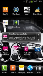
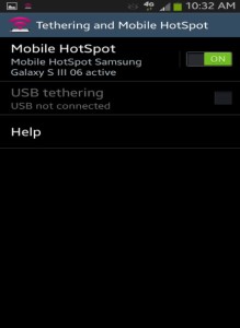
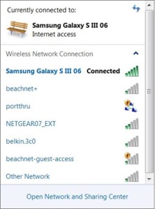
The steps taken to connect to the Wi-Fi hotspot and connection to the Arxterra Control Panel on the mobile data connection is shown below. The mobile phone used was a Samsung Galaxy S3 and the test was run at the site of the route where the robot will navigate. The following set up tutorial is performed with an android phone (Samsung Galaxy S3).

Step 1 – Click on the Mobile Hotspot app on the phone
step1

Step 2 – Turn on Mobile Hotspot
step2

Step 3 – Connect to the mobile data connection using any device with wireless connectivity (password required)
step3

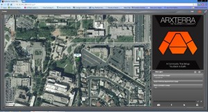
Step 4 – Log in to the Arxterra Control Panel
step4

Step 5 – Start control your robot
step5

Discussion by Robert Licari

Wireless provider

The wireless provider is a simple matter considering that most, if not all, of our employees carry a cellular phone and an almost equivalent number of employees carry smartphones. Taking this into consideration, we can simply utilize the sources provided by different service providers to view their coverage maps; however, they lay claim to all areas around long beach as a part of their “Nationwide Coverage” slogans dictate. To get a more accurate map, utilizing www.sensorly.com (a free coverage map source) we can see that Long Beach is not completely covered by any of the major providers. Sensorly, however, is a user-dependent tool and is thus, not 100% accurate either, but it does provide us with an idea of actual users, in the field, using data at varying speeds from 4G down to 2G (which are relevant for our purposes). Overall, this will not be an issue considering that the field is nearby one of the many sensorly tested areas, which we can safely assume and test for signal strength and viability.

Bandwidth and Range

Our major concern is Bandwidth and Range when we consider our service provider. This factor is almost completely dictated by the amount of customers utilizing bandwidth as well as the distance the client (in this case a laptop) is from the smartphone. This is reliant also upon the service coverage area that we are working in. To be clear the International Telecommunication Union has NOT set a defined standard for the rates of mobile data services. Upon further research, one can find multitudes of numbers with even more multitudes of tests done in controlled or uncontrolled environments. The reason for this is that it is highly dependent upon the above factors and is greatly influenced by movement of the hotspot. Generally speaking, it is widely accepted that we shall be receiving approximately 300 kb/sec. To be blunt, this number is not random, but in a world where some receive 25 Mb/sec and others that receive 25 kb/sec, it is difficult to accurately pinpoint an exact number for any particular time of day. On average, 300 kb/sec will be our acceptable bandwidth, which will begin to deteriorate as we begin to venture farther and farther from our client to a maximum distance of around 50 feet.

Cost

The final concern that we have will be cost, which is, quite possibly, the most varied of our concerns because this is strictly on a case-by-case basis. One person could have an unlimited data plan, while others could have a fixed data download plan that will limit them for the experiment. For this reason, should this be the final factor in deciding whether or not this is our solution, it is simply a matter of finding a volunteer with unlimited data to have their cellular phone be a mobile hotspot.


Buy a Wi-Fi/4G access point

by Vinh Khoa Ton

Introduction

A Wi-Fi/4G access point is a location that provides users wireless network. Nowadays, most electronic devices are equipped with a wireless adapter (mobile phone, laptop, tablet, watch, etc.), the demand for wireless connection increases rapidly. The Wi-Fi hotspot could be found usually in public areas such as airports, post offices, coffee shops, or fast food restaurants while the 4G hotspot could be found almost everywhere you go. The 4G access point is a portable device that give you Wi-Fi access.

Cost and Range

Wi-Fi hotspot is quite affordable offered by most major network carriers. AT&T offered Wi-Fi on the spot with $3.99 to $7.99 per session. However, Wi-Fi hotspot is limited only to public areas that offer the service. The track field that we need to have Wi-Fi access does not have a Wi-Fi hotspot nearby.

4G hotspot (or mobile hotspot) has more coverage range and gives more flexibility for outdoor internet usage such as hiking, camping, biking at some remote areas. A hotspot device usually works well within 50 feet and could support up to 5 users at the same time.

For example, FreedomPop offers 500 MB of 4G data free every month and charge $0.02 for every extra MB used.

freedompop plan

However, the drawback is that cost for the portable hardware is expensive, ranging from $50 and up to more than $100.

freedompop price

Conclusion

The Wi-Fi hotspot provides a pay-as-you-go option that suits our need for a short project demonstration but lacks the flexibility in coverage range. The 4G hotspot could provide the needs in coverage range but the cost is too expensive. As the reasons above, we does not choose this method as our solution because it does not meet all of our requirements.


System/Subsystem Design

by Suhyun Kim

System Block Diagram

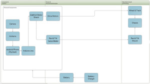
block 

The image above provides an overview of how each component is linked together within the rover. 

Camera/Phone:
From a remote location, using the Arxterra interface we will be able to communicate via the phone and camera.  The camera will provide an image to the Arxterra interface.  Through the phone, we can use the interface to communicate with the microcontroller.

Microcontroller:
The microcontroller subsystem includes an Ardiuno Uno and a Motor Shield.  The Uno will be the bridge between the phone and the motor shield.  The motor shield is used to control the 2 motors and 2 servos on the rover.

Battery:
The rover will have several batteries.  One dedicated battery to power the microcontroller and one to power the motors and servos.  The batteries must provide enough power for all of these components until the end of the mission.

Motors/Servos:
The motors will drive the wheels.  The motors must provide enough torque to move and enough RPM to fulfill our speed requirement.  The servos must provide enough torque to pan and tilt and must provide a range of vision as described in the test plan.

Detailed Cost

By Maxwell Nguyen and Anthony Vo

The first link below provides the BOM for the standard RoSco as provided by Arxterra.  The second link sums the price of each part in order to provide a projected cost of the standard RoSco.

Bill of Materials:
Standard RoSco BOM

Standard RoSco Cost:
https://www.dropbox.com/s/kpw4iobx1h1ova2/standard%20rosco%20bom.xlsx

The link below is the projected cost of the rover taking into account of parts replacement.  This link provides a complete BOM, which includes parts description, quantity, price, and source.

New Rover BOM:
https://www.dropbox.com/s/439vaho8fhycdth/Rover%20Projected%20Cost%20new.xlsx

Task Descriptions

by Maxwell Nguyen

  • 1.      Trade off studies: 1 week

Compare different motors and servos.  Determine which motor and servo will best meet our subsystem requirements.


 2.      Test motor: 1 week
Test/record current draw and RPM of motors at different voltages.


 3.      Test Servo: 1 week
Test/record current draw of servo depending on required torque.  The required torque will be simulated by lifting an object.  Verify torque load of servo.

 4.      Mirror Study: 1 week
Test mirror functionality with phone camera.  Record a video with mirror in place at different angles.

 5.      Battery test: 1 week
Measure/record current and capacity of the battery.

 6.      H-Bridge Study1 week
Research and report the functionality and purpose of an H-bridge.  The new Adafruit Motor Shield comes with an H-bridge on board.  Research will be done on how to implement the H-bridge into the rover design.

 7.      Program testing:  1 weeks
Learn and write up a program to test servos and motor shield.  Coding will most likely be done in C++.

 8.      Motor shield test 1 week
Confirm that the motor shield is working properly by testing injunction with motors and servos.

 9.      Track research 2 weeks
New track design will be based on tank treads.  The goal will be to design tracks that can be printed as separate individual pieces.  The pieces will be able to attach to each other to create a single belt.

10.     Phone to Arxterra test:  1 week
Download and install Arxterra app onto the teams dedicated Samsung Galaxy S3.  Confirm that the phone can communicate to Arxterra and provide and image via phone camera.

11.     Arxterra to Arduino test:  1 week
Confirm that the Arxterra is communicating to the Arduino Uno.  Confirm that the Arxterra user interface can relay signals to the Arduino and Motor shield.

12.     Remodel Head:  2 weeks
Design a new head that will support the phone and allow for panning and mirror tilting.

13.     Print parts:  3 weeks
Send orders to manufacturing division to get parts printed

14.     Assemble Rover 1 week
Rover and track assembly will be done.  Some sanding and reshaping may be required if parts do not fit together.

15.      Conduct Test Plan: 2 weeks
Test and verify that rover can achieve the requirements laid out in the test plan.

Test Plan

By Suhyun Kim and Robert Licari

For our new design of Rover, we will do some tests such as electrical tests, software tests and functional tests. The electrical tests would be minor and basic tests, and software and functional tests would be main tests for our project.

Electrical Tests:  1 week duration
Electrical Tests will mainly include Current and Voltage Tests of battery, motor, servo converter and microcontroller. 9VDC motor supply and 9V UNO supply will be tested to ensure that the supplies are providing the proper amount of current and voltage required to power the rover.  Also, the two of DC motor and Servos will be tested for their current draw because all of motors are core parts in controlling the Rover.

   Test Type       Test sub-type
Battery 12VDC Motor Supply
  9V UNO Supply
Motor DC Motor (x2)
Servo Servo (micro)
Microcontroller Arduino Uno

Motor Shield


Software Tests: 1 week duration
On the Software Tests, we will test how applications of Arxterra are well connected to Arduino Uno and Control Panel. Also, we will check Image Processing parts. These tests would influence on how the Rover is exactly navigating through the course.  We will confirm that the Axterra interface can communicate through the phone with the microprocessor.

Test Type Description
Applications with Control Panel How applications are well connected to Control Panel
Control Panel with Arduino Uno How Control Panel are well connected to Arduino Uno


Functional Tests: 2 week duration
Functional Tests is our project’s main tests. It will include Speed Tests, Turn Tests, Pan Tests and Tilt Tests. In speed tests, we will do forward speed and backward speed tests on flat surface and natural surface. We will check that Rover can navigate like calculated speed on any surfaces, especially natural surface.  To navigate through designated course, the Rover has to turn left side and right side. Therefore, we will do 90 degrees left and 90 degrees right turn tests from forward (normal position). Pan tests will be same to turn tests. Also, because rover will have a mirror to secure views, we need tilt tests.  We will test 45 degrees upward tilt and downward tilt from normal position. 


Test Type Test sub-type Description Desired Results
Speed Tests Flat surface A 10 meter “dash” across a flat, smooth, surface.  


Calculated Speed @0.200277 m/s

  Natural surface A 10 meter “dash” across a natural, earthen, surface. (loose earth).
  Flat surface Test

(Reverse)

A 10 meter “dash” across a flat, smooth, surface backwards.
  Natural surface

(Reverse)

A 10 meter “dash” across a natural, earthen, surface. (loose earth) backwards.
Turn Tests Right Turn A 90 Degree Turn Right from Normal (Forward) Position  
  Left Turn A 90 Degree Turn Left from Normal (Forward) Position  
Pan Tests Pan Right A 90 Degree Pan Right from Normal (Forward) Position  
  Pan Left A 90 Degree Pan Left from Normal (Forward) Position  
Tilt Tests Shutdown A Test -45 Degrees from Normal (45 Degrees)  
  Normal A Test at 45 Degrees  
  Look-up A test +15 Degrees from Normal (45 Degrees)  
  Sky box A Test +45 Degrees from Normal (45 Degrees)