Level 1 Requirements – Final Iteration

By Kristine Abatay – Project Manager
and Matthew Clegg – Computer & Control Systems

The final statement of our mission objective created a new level 1 requirement regarding wireless control of Spiderbot through the Arxterra control panel and Arxterra Android app. The following is the final list of the level 1 requirements for Spiderbot, along with their corresponding verification tests:

1. Completion of the project will be achieved by May 12, 2014.

This is the date of the final assigned specifically for EE400D.

Test: If project Spiderbot is completed by this date, then this requirement will have been achieved.

2. The legs and complete chassis components of Spiderbot will be designed to extend into three spatial dimensions.

Test: This requirement will be verified within the SolidWorks program, which enables our manufacturer to define the three axes of a design. If, at any rotated view of a component design, three separate pieces of the design can be chosen to define a respective x-, y-, and z- plane, then this requirement will have been fulfilled.

3. Match the speed of the track rover project on a flat surface. This value was determined to be 0.2003 m/s.

Test: In order to verify this requirement, a flat surface, straight-lined course will be measured out and Spiderbot will complete the course while being timed. The resulting quotient of the length of the course, with the amount of time it will take Spiderbot to complete the course, will be calculated. If this value is equal to or less than the calculated rover speed, then requirement will have been achieved.

4. Operate in accordance with the CSULB College of Engineering Health and Safety Policy            

(found here: http://www.csulb.edu/colleges/coe/views/safety_and_environment/safety_policy.shtml)

Test: The CSULB College of Engineering Health and Safety Policy states that

“Faculty…shall: Implement the university’s Health and Safety Policy and all other university safety programs in work areas under their supervision/control.”

If Professor Hill, a faculty member of the CSULB College of Engineering, approves the operation of Spiderbot in the classroom, then this requirement will have been met.

5. Have a height clearance of 4 in. and width clearance of 2.5 in.

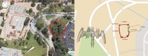
These values were obtained through measurements of the largest obstacles found in the assigned course. The following image is an aerial view of the course that Spiderbot will have to maneuver. The total length of this route was measured to be 41.80m. It is located in the eastern wing of the CSULB campus.

Blog10_image2

Test: Verification of this requirement will be done by measuring the height clearance, as well as the length of one leg sweep of the fully constructed Spiderbot.

6. Spiderbot will be capable of being wirelessly controlled using the Arxterra Control panel, in conjunction with the Arxterra Android phone application.

Test: If a command sent to Spiderbot through the Arxterra Control panel matches the command that Spiderbot executes during operation from the Arxterra Android phone application, then this requirement will be satisfied.

Final 3D Model

By: Simon Abatay – 3D Modeling and Manufacturing

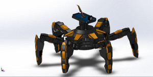
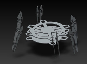
The final model is here! The following image is the final design that will be manufactured for Spiderbot that was created using SolidWorks:

Blog9_image2

This final design was done in response to our project requirement that all components of Spiderbot’s body be three-dimensional. The chassis is composed of both 3D and 2D elements, but as a whole, it is three-dimensional. The inner portion of the chassis contains two 2D disks that will serve to hold the operational components of Spiderbot (i.e. microcontroller, breakout boards).

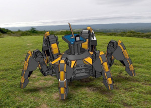
Just for kicks, here is an image of Spiderbot in a real-world setting (not shown to scale, of course):

Blog9_image3


Current Test of the Power HD High Torque Servo 1501 MG

Experiment Conducted by: Matthew Clegg (Controls – Spiderbot), Elaine Doan (Systems Engineering Division), and Kristine Abatay(Project Manager – Spiderbot)

Test Setup written by: Matthew Clegg and Kristine Abatay

 Discussion and Results written by: Elaine Doan

A test will be performed in attempt to find the current the Power HD High Torque Servo 1501 MG consumes during operation of the Spiderbot or Biped when 6 volts is applied.  From the test, the idle current of the Power HD High Torque Servo 1501 MG will also be identified.

Test Setup

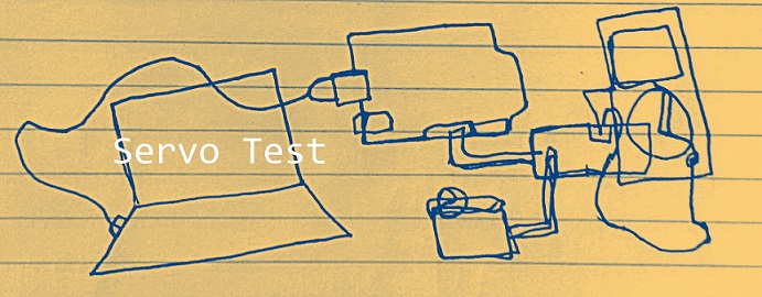
The following setup was used for this test:

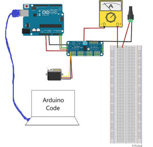
Blog7_image2


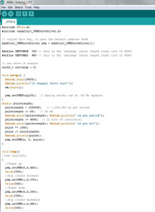
The test was run using breakout boards since they will be used to power the many servo motors in the final construction of Spiderbot. A plastic indicator was attached to the wheel of the servo, which was placed in front of a protractor since the test code used was based off of PWM adjustment as opposed to angle. The following image shows the test code that was used. Matthew Clegg modified the code that was provided by Adafruit (the brand of the breakout board used) to cater to this test:

Blog7_image3


The final construction of Spiderbot will involve the use of metal brackets to securely connect the servos with the designed components, so a metal bracket was also used in this test. In order to acquire accurate current readings and properly mimic the motion that Spiderbot’s legs will use, small weights were attached to the end of the bracket.

The estimated weight that a single leg servo on Spiderbot will have to support came out to be 437.55 g. This value was acquired using estimates provided by SolidWorks for the designed components and actual weight measurements from a scale for components that we had. The total is comprised of a single femur and tibia component, as well as three servos to account for a single leg, and 1/6 of the chassis design with all of the components it will hold (i.e. Android phone, pan and tilt platform). The total mass that was tested went up to as high as 500 g in order to account for the possibility of undershooting the final mass, keeping in mind the total mass that the servo can handle with the extended arm attached. The following image provides an idea of the approach taken in finding the current for varying lengths of the servo arm:

Blog7_image4


The first panel of the image shows the metal bracket and the small weights that were attached to it. In order to maintain a constant test mass with a varying arm length, the weights were first placed on the inner and outer portions of the bracket without exceeding the initial length of the arm, as depicted in the second panel of the image. Finally, the masses were stacked on the bracket to extend the length of the arm, as shown in third panel, and more current measurements were obtained.

 The current read through the multimeter varied constantly throughout the test, so the values that were recorded were the largest values that appeared consistently on the multimeter for each angle value. A quick video depicting the setup of this servo test can be found in the link below:

http://youtu.be/b5Dv5LfQsCQ

Discussion and Results

When working with servos, there are two currents worth noting: the idle current and the stall current. The idle current is the current consumed by the servo when it is not performing but connected to the power source. It is important to identify the idle current because it will provide users with the upper bound on how long a battery powered application can run. The stall current is the maximum current drawn by the servo when it is performing. The stall current will provide users with the minimum current requirement for the power supply. The actual current a servo consumes during operation will vary between the idle current and stall current. Servo currents usually are not specified by the manufacturer and the user is required to run tests to find the idle current and stall current. It’s easy to measure the idle current since it is low, constant, and only requires a simple connection to a power supply. A standard servo such as the Power HD High Torque Servo 1501 MG will have an idle current around 0.01 -0.03 amps depending on the power supply. Stall currents are more difficult to measure because stalling a servo can result in a damaged servo. A standard servo such as the Power HD High Torque Servo 1501 MG will have a stall current around 1 amp (finding the stall current of the Power HD High Torque Servo 1501 MG will not be attempted in this test.  Finding the current a servo draws during normal operation of the Spiderbot and Biped will be attempted instead). The current will be approximately linear with the supply voltage, so the currents drawn at 7 V will be almost double those at 4 V. Adjusting the rotational degrees of the servo will typically draw more current linearly. Increasing the torque by ten times will typically draw ten times the current.

Part A
IDLE CURRENT

Idle Current at 6.0 V = 0.03 amps

Part B
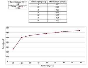
SHAFT ROTATION VS CURRENT

 Blog7_image5

The graph shows how the current draw is affected by the increasing rotation of the servo’s shaft from 10 to 90 degrees. The current drawn increases steadily by approximately 10 mA as the rotation degrees increase by increments of 10 degrees. 

Part C
TORQUE VS CURRENT


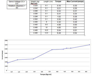
Blog7_image6


The graph shows how the current draw is affected by the increasing torque from 0.10 to 6.48 kg•cm. The current drawn increases by approximately 40 mA as the torque increase by increments of 1 (kg•cm). 

Design – First Iteration

By Simon Abatay, 3D Modeling and Manufacturing

After a review with the Robot Company’s President, the initial tibia design was deemed unsatisfactory due to its flat nature. In order to tackle this, I decided to modify my original design to give it a more 3-dimensional appearance. My intentions with this modification step were to maintain some semblance of its original shape, while providing it with a newfound presence of solidity.

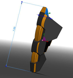
Blog6_image1

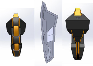
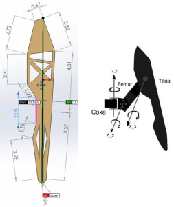
The picture above shows that there is a defined depth in all 3 axes of the tibia. This satisfies the 3-dimentional objective.  The tibia still retains its 7 inch height and has a shape similar to the initial design to satisfy the height requirement. In order to save weight, the inside of the tibia will be slightly hollow. The overall design will be constructed with enough material to retain the structural integrity of the tibia despite its hollowness. Below is an image of multiple views of my tibia design:

Blog6_image2

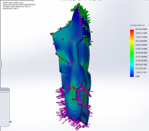
To test the quality of the design, I put it through a proper stress simulation in Solidworks©.

Blog6_image3

The green arrows in the image above show where the tibia will garner most of its support. The purple arrows represent where the external forces are being applied to the design. I chose to apply force in every possible direction against the bottom of the tibia. This was done in order to simulate the idea of the spider walking, since that motion is the time when tibia undergoes stress in all directions. The spectrum to the right of the picture shows the level of stress each section is undergoing. The stronger the section the more blue it is, and the weaker the section, the more orange and red. This simulation shows that when the tibia undergoes 50 Newtons of force in each direction, it can retain its shape with minimal deformation. This simulation shows that the tibia’s structure is sound.


Mission Objective Modified

By Kristine Abatay, Project Manager

Following the group’s preliminary design review presentation, we met with the Robot Company’s President and modified our mission objective. Our new mission objective is:

Complete a hexapod robot project whose creation will achieve a speed that matches the current Robot Company rover project, operate safely, be capable of maneuvering a predetermined route in a forest-like setting, and have a body comprised of three-dimensional components.

Trickling down from this objective allowed us to create a fifth project requirement:

5. The legs and chassis components of Spiderbot will be designed to have three dimensions.

The other project requirements can be found ina previous post where the project was introduced:

 https://www.arxterra.com/spiderbot-life-times-vol-2/

Additionally, the following tests have been created to verify the project requirements that have been written (they are listed in the order from which they have been introduced):

Verification Tests:

Test 1
If project Spiderbot is completed by May 12, 2014, then this requirement will have been achieved.

Test 2
In order to verify the speed requirement, a flat surface, straight-lined course will be measured out and Spiderbot will complete the course while being timed. The resulting quotient of the length of the course, with the amount of time it will take Spiderbot to complete the course, will be calculated. If this value is equal to or less than the calculated rover speed, then requirement will have been achieved.

Test 3
The CSULB College of Engineering Health and Safety Policy states that “Faculty…shall: Implement the university’s Health and Safety Policy and all other university safety programs in work areas under their supervision/control.”

If Professor Hill, a faculty member of the CSULB College of Engineering, approves the operation of Spiderbot in the classroom, then this requirement will have been met.

Test 4
Verification of the height requirement will be done by measuring the height clearance, as well as the length of one leg sweep of the fully constructed Spiderbot.

Test 5
The requirement of a three dimensional design will be verified within the SolidWorks program, which enables our manufacturer to define the three axes of a design. If, at any rotated view of a component design, three separate pieces of the design can be chosen to define a respective x-, y-, and z- plane, then this requirement will have been fulfilled.

Speed Calculations & Component Modification

By Matthew Clegg, Computer and Control Systems

In order to tackle the initial calculated speed requirement of the rover project, we would need a starting point for Spiderbot. For this reason, I decided to make a calculation to determine the speed that the servo motors on Spiderbot’s legs would need to move in order for the entire robot to match the rover speed.

To try to estimate a possible speed for Spiderbot, I first calculated a velocity based on the speed of the servo motors. A servo’s rated speed is how fast, in seconds, the arm can move 60 degrees. To apply this to Spiderbot, I took into account the motion of the bot in a tripod gait, which is the most efficient walking pattern.

Assuming the length of the femur to be 5” (the value assigned to the initial Spiderbot design done by Simon Abatay in manufacturing) and the femur moving forward at a 60 degree angle (the speed rating provided by servo motor specification sheets), then using trigonometry,

eqn1 

In SI units, each sweep of the leg will cover 0.109 meters. In the tripod gait, the leg will move up 30 degrees, forward 60 degrees, then back down 30. Knowing the sweep of the leg is 0.109meters, he came up with a formula to find the time in seconds

eqn2

Dividing this time by 2 to account for both motions of the gait results in

 eqn3

The total degree movement of a leg is 30, 60 and 30 degrees. He divided 0.26s by two to find out how fast the servo moves 60 degrees to reach a speed of

 eqn4 

These calculated values are our project’s starting point. They are subject to change once more progress is developed with the rover project and more concrete details are obtained.

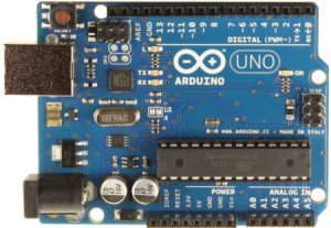
Lastly, it has come to our attention that using both the Mega ADK microcontroller and Adafruit breakout boards (as stated in a previous blog post for this project) would be redundant. The Mega ADK was considered because it could accommodate the amount of servos we would need to construct Spiderbot. Breakout boards were considered because it was the route that both spider projects took last semester in terms of design. We decided to instead use the breakout boards along with an Arduino Uno R3 microcontroller since we already have one in our possession, so the decision was mostly based out of convenience. Using these two components together will essentially be the same as using a single Mega ADK. An image of our newly chosen component can be seen below:

Blog4_image1 (1)
 (Image found at: http://arduino.cc/en/Main/arduinoBoardUno)


Spiderbot: Initial Design

By Simon Abatay, 3D Modeling and Manufacturing

Picking up from last semester’s Spiderbot project, the design for this project will have 6 legs. Though the name ‘spider’ implies 8 legs, translating it to a project would become very pricy in the long run since it would require more materials and power to construct.

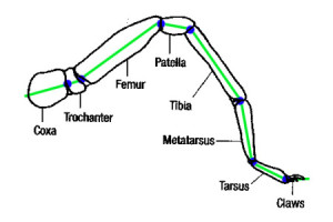
Despite the difference in leg amount, we still wanted the design to be similar to an actual spider. The image below is of an actual spider leg. From this, we can see that spiders have 7 joints.

Blog3_image2

(Image from: http://havoc20.wordpress.com/2010/11/13/spider-tibia-structure/)

This would translate to seven servo motors per leg, and at 6 legs that would mean 42 servo motors! To save money on the final design, we’ve reduced our spider leg design to the 3 main parts: the coxa, femur, and tibia. This is the case with most hexapod designs that can be found online.

Three joints with a single motion each will mean each leg will have three degrees of freedom. This reduction will provide smooth movement for Spiderbot while walking and enough support for the spider to stand when stationary.

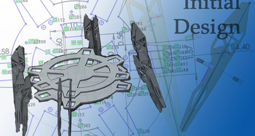
Keeping the reduction of joints in mind, the following image is my initial design of the spider’s tibia, which was created in the program SolidWorks.

Blog3_image3
One of the main issues with last semester’s design was maintaining balance while stationary. To avoid this, each tibia portion will have a tibia “plate” on opposite sides of the servo motor. To keep the whole tibia portion from collapsing on itself, each pair of tibia plates will be supported by metal spacers or standoffs.

The tibia will measure 7 inches in height as a response to the project requirement of clearing an obstacle of 4 inches tall, located in the planned route for Spiderbot.

For the body portion of Spiderbot, I plan to use a circle-based design since its shape will alow for uniform weight distribution. This way, the tibias will be evenly spaced out and, assuming the hardware will be placed in the middle of it, the center of gravity will remain at the middle of the Spiderbot.

Blog3_image4

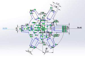
The image below shows the design of the base plate. The radius of the center portion is 3 inches to accommodate the power source, the microcontroller, the servo breakout boards, and the Android© based cellular phone.

Blog3_image5

The extensions of the circle have a radius of 4.4 inches to accommodate the servos and their proper positioning (see rectangular cutouts).  The rest of the cutouts are for weight saving and heat ventilation. Seeing as a solid plate would have unwanted and unnecessary weight, it would be best to make cut-outs of the plate while at the same time leaving enough mass and surface area for the other components.

Spiderbot: Chop Suey Returns

By Matthew Clegg, Computer & Control Systems

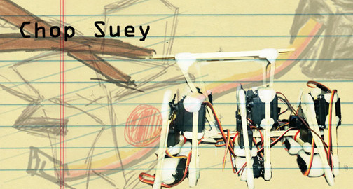
Chop Suey has returned! David Gonsalez, a member of the Hexapod team from the previous semester, has loaned us the hexapod prototype he built. Having access to an already built prototype will save time and money because we will not have to devote resources to make one. It will also allow me to visualize how the servos will be working to move the legs and body, depending on which type of walk, or gait, the Spiderbot will use.

We scouted the area where Spiderbot will be required to move through and took measurements of obstacles. After previewing the terrain, it seems that Spiderbot may have to switch between two different types of gaits in order to overcome obstacles and move with good speed. The two gaits in consideration are the tripod gait, which will allow for a greater speed on level surfaces, and the wave gait, which is slower but will allow for more stability over uneven terrain.

Further explanation of these gaits can be found in the blog of the previous semester’s Hexapod project.

Sprinkler_Top

The length of some of these obstacles will also affect the distance that the legs of Spiderbot will have to sweep.  This will be determined in part by the length of the legs. The photo above indicates that the maximum width of the obstacles from a top view (both sprinkler heads and branches) measured to 2.5 inches, which is the leg sweep that will be required of Spiderbot.

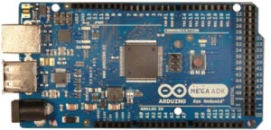
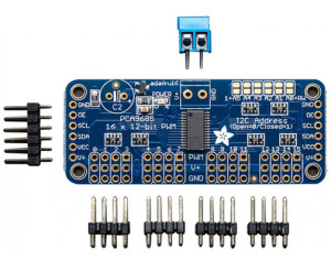
In accordance with the previous semester’s design choices, we have also decided to use the Arduino Mega ADK, as well as the Adafruit 16-Channel 12-bit PWM/Servo Driver in Spiderbot’s design. The Mega ADK will allow for fewer complications when interfacing with an Android smartphone because of the dedicated usb port placed on the board. The Mega ADK will not be able to support the number of servos we will be using (a total of 20 servos!), which is why we will be using servo drivers. The use of the drivers will also free up processing power from the Arduino ADK. These components are shown below:


ArduinoADKFront450px

Image from: http://arduino.cc/en/uploads/Main/ArduinoADKFront450px.jpg


adafruit-16-channel-i2c-servo-controller-1_1

Image from: http://www.robotshop.com/media/catalog/product/cache/1/image/800×800/
9df78eab33525d08d6e5fb8d27136e95/a/d/adafruit-16-channel-i2c-servo-controller-1_1.jpg

The next thing in store for Spiderbot: trade-off studies of servo motors for leg operation of Spiderbot and familiarization with everything Chop Suey has to offer to better our design.

Spiderbot – Life & Times (Vol. 2)

Spiderbot_Logo_smaller

By Kristine Abatay, Project Manager

main()
{
printf(“hello, world!”);
}

It is a new semester at Robot Company and with it, a new Spiderbot!

 Our mission: construct a six-legged robot that will match the speed of the Robot Company’s rover project, operate safely, and have the capability of maneuvering a route in a natural setting.

 This robot will have a spider-like appearance and walk, but with six legs instead of eight, all the while being controlled wirelessly using an application for Arxterra, designed for Android smart phones. Spiderbot will achieve a speed of 0.2003 m/s on a flat surface – the calculated speed using specifications from components of the rover project last semester.

Click here to see the calculation used to determine the speed requirement  

The natural setting that Spiderbot will be able to maneuver is located on the East Wing of the CSULB campus as shown by the following map:

Map

 Our group surveyed the area and created a route for Spiderbot to complete as indicated in the picture above and the total length measured to roughly 42 m. This is the same path that will be used to test both the Rover and the Hexapod projects. A quick run through of the route can be found in the following link:

The pictures below are some of the obstacles encountered while surveying the Spiderbot route. A sprinkler head with a height of roughly 4 inches and a branch with a width of 2.5 inches were the most notable obstacles. These measurements will dictate the overall body design of our Spiderbot. In addition to these design requirements, our Spiderbot will function properly while following the health and safety policy of the engineering department of CSULB (found here: http://www.csulb.edu/colleges/coe/views/safety_and_environment/safety_policy.shtml).

SONY DSC

Our date of completion is set for May 12, 2014 so stay tuned for future updates as we progress in our construction of Spiderbot!