Spring 2018 3DoT Hexy: Determine Gear Design

By: Eduardo De La Cruz (Project Manager and Manufacturing Engineer)

Verified by: Eduardo De La Cruz (Project Manager and Manufacturing Engineer)

Approved by: Miguel Garcia (Quality Assurance)

Table of Contents

Introduction

     Since we are going to base our design of Spring 2016 3DoT David, we will need to implement a functional cam system that is either similar or better in design then that constructed by the Spring 2016 team. In this blog post we will: go over current gear ratio from existing 3DoT david cam system, determine the cam system design for Hexy, potential driving and driven speeds for our design (based on motor selection), go over the gears we will use , and implementation.

Related Requirements

  • To keep cost down, and keep a toy aspect , the robot shall use only 2 micro motors to drive the movement of the robot.
  • The robot will need to navigate remotely through a custom built maze (built by AoSa image), memorize the path it took, start over, and autonomously travel through the path it took.
  • The robot shall operated in a tripod form, having three legs (2 outer in one side and middle leg in the other side) to provide stability while moving.

Update (March 15, 2018)

We decided that pursuing a 3:1 configuration would be the way to go. This is due mainly to the femur-to-gear joints. 20T gears have a smaller surface area over which to place joints that need to be made bigger based on assembled prototype.

Trade study (March 6, 2018)
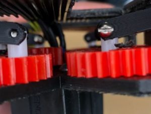
3DoT David’s Cam

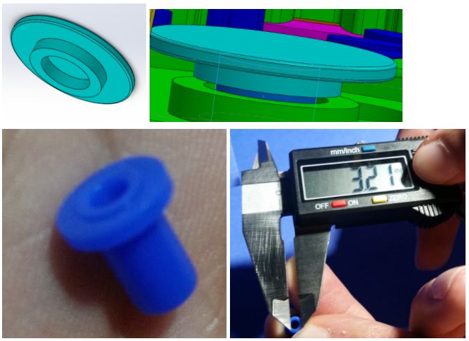
     Since we were given access to the 3DoT David robot and their blog post research, we were able to analyze the design more in detail. The manufacturing department even went the extra mile to model gears from the robot on solidworks by measuring the pitch diameter, outer diameter, tooth thickness, addendum, dedendum, pressure angle and face width using a digital caliper (click here for meaning of these variables). Below is a model of 3Dot David cam system:

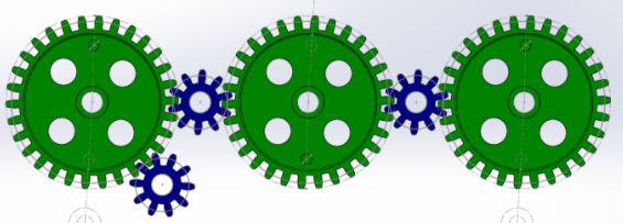
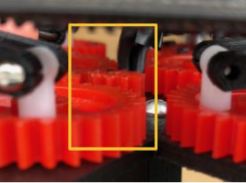
Figure 1: Current cam design 

The gear ratio for 3DoT David’s cam is 3:1. The small gear has 10 teeth with a pitch diameter of 10 mm and the big gear has 30 teeth with a pitch diameter of 30 mm. The driving gear (where motor connects) is the lower left blue gear. According to, Spring 2016: 3DoT David Gear Train , 3DoT David is designed to drive the larger gears at 2 rev/sec, therefore, the driving speed of the motor should be 360 RPM. The 3DoT David team decided that it would be best to use geared motors rated at 450 RPM at 6V and use a booster shield to reach 5 V to get to 360 RPMs for the input gear (click here to read more on how they determined this motor choice). A video of 3DoT David cam performance can be seen by clicking here .

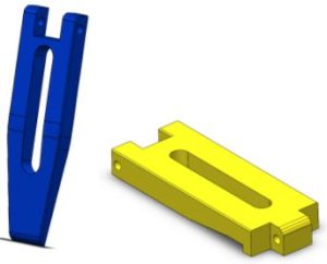
The cam system we will use

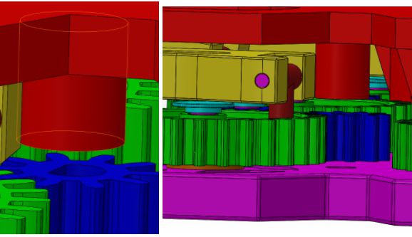
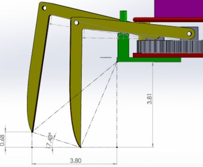
So far two potential cam designs are going to be used to experiment on. The first one will be 3DoT David’s 3:1 configuration, and the second one will be a 2:1 configuration shown below:

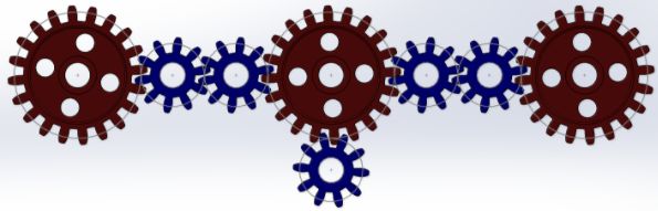
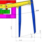
     Figure 2: Alternative design

For this configuration we would use small gears with 10 teeth and large gears with 20 teeth. Since gears sizes are scaler, modeling 20 tooth gears from 10 tooth gear, generated above, was not an issue. The reason for using this configuration is that it would reduce length of 3DoT Hexy by 6 mm from 3DoT David design, and reduces length of femurs that would connect to the red gears. This document will be updated when we determine the configuration we go with for our cam system.

Required Driving and Driven Speeds for our design choice, under ideal conditions

Note: Driving Gear (G1) = small gear connected to motor.

Driven Gear (G2) = large gear used to move legs.


For the most part we want our robot to rotate its legs anywhere between 1 and 2 rev/sec. Therefore we will calculate speeds for 1 and 2 rev/sec for 3:1 cam system, and 2:1 cam system, both shown above. Calculations were done using Gear train document as a reference from wikipedia.

Note: G1 speed = Wa, and G2 speed = Wb

Na = teeth on G1, and Nb = teeth on G2

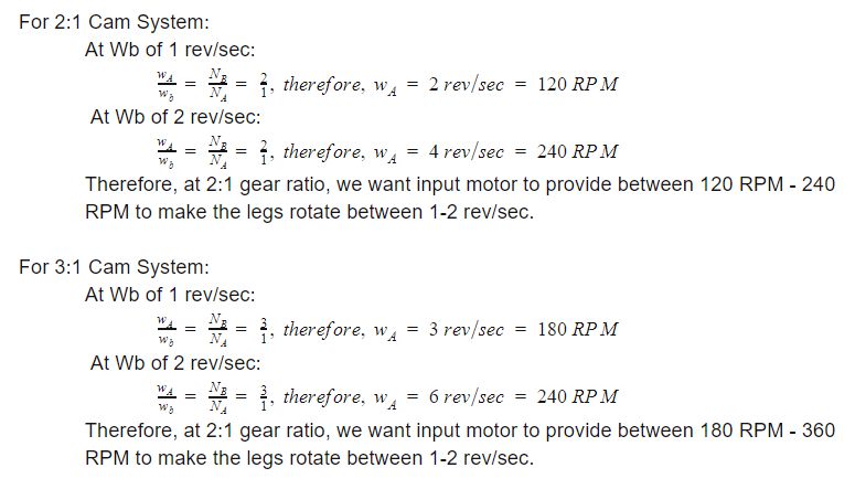
Figure 3: Calculation for different cam configurations 

The Gears we will use

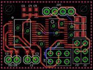
There are two methods of obtaining gears for our cam system: buying or fabricating gears. After consulting with Prof. Hill over the possibility of fabricating gears, Hill recommended we just pursue purchasing gears. Therefore, the manufacturing department went on a hunt for purchasable gear sets. Taking into account that we need gears with 10, 20, and 30 teeth to model our two configurations and the source material on gear instability done by the 3DoT David team we found the following two gear sets on Amazon:

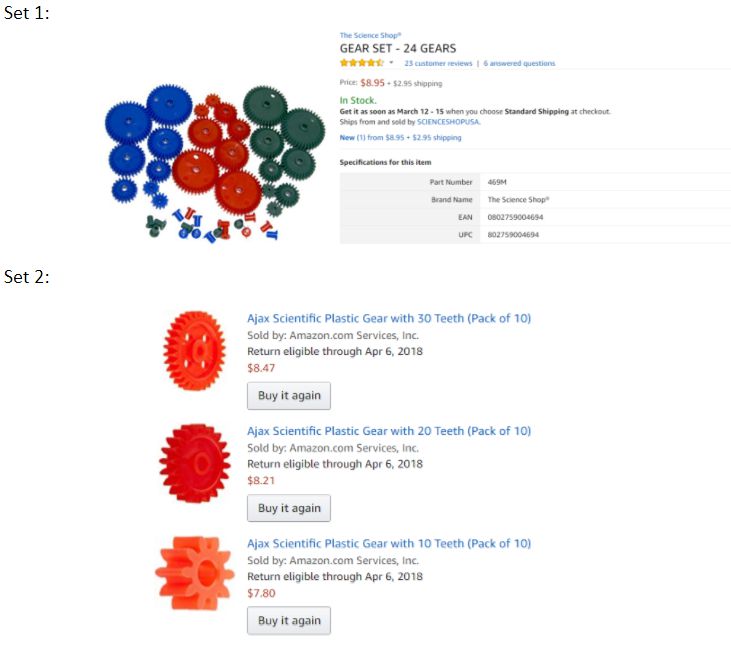
Figure 4: Out sourced gears 

Both sets have the desired pitch diameters of 10, 20 ,and 30 mm. The advantage of picking Set 2 is that it will be the same gear set that 3DoT David used.

In case these gears don’t work, we always have the gears the manufacturing department accurately created from scratch using solidworks for CNC cutting:


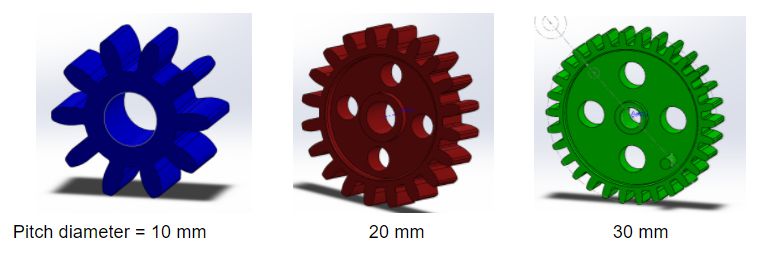
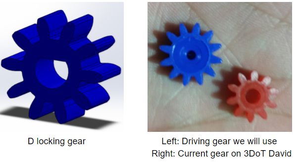
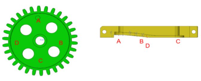
Figure 5: Gear generated in Solidworks 

Note:

These gears cannot be found in Solidworks libraries. These models were accurately obtained by determining the pitch diameter, outer diameter, tooth thickness, addendum, dedendum, pressure angle and face width using a digital caliper and using 3DoT David’s Gears as a reference.


Files for these gears can be found below:

Gears

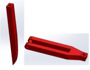
How final design would look with legs connected
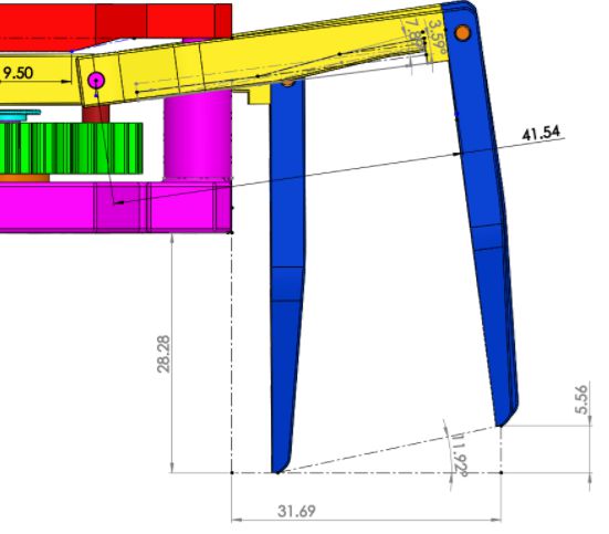
3:1 System:

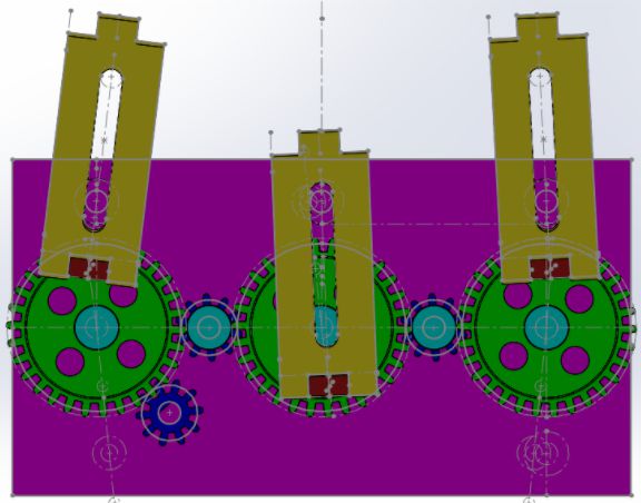
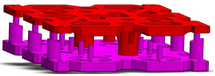
Figure 6: One side of assembled cam 

This design will be mirrored along the vertical axis and femurs will be positioned in opposite order of the ones above: outer legs in an middle leg out to have 3 legs on the ground at all time for balance (tripod).

Note:

2:1 system will have the femurs connected to the red gears and would be positioned in the same way as above .

Conclusion

Currently we are more interested in pursuing the 3:1 cam system for our design, however, we will attempt to model the 2:1 system to see if it would be better for our design instead of 3:1. We will update this document after the rapid prototype has been made modeling both gear designs. From this blog post our E&C was able to determine motor selection based on the gear calculations above. We will be using a 530 RPM at 6 V high torque micro gear box motor, will see RPM rating at 3.7 V (battery rating) and determine whether or no we need a boost shield to drive the cam system at the desired RPM.

Resources

  1. https://www.arxterra.com/3dot-david-gear-train/
  2. https://www.arxterra.com/3dot-david-rapid-gear-instability/
  3. https://en.wikipedia.org/wiki/Gear_train/


Spring 2018 3DoT Hexy: RGB Color Sensors

By: Kris Osuna (Electronics & Control Engineer)

Verified by: Eduardo De La Cruz (Project Manager and Manufacturing Engineer)

Approved by: Miguel Garcia (Quality Assurance)

Table of Contents

Introduction

   A RGB sensor is going to be needed to allow 3DoT Hexy to detect intersections. A different color will be placed at every intersection to allow our robot to know the type of intersection.  We will be using the RGB Light Sensor – ISL29125 to get values from printed paper.

Components

  • Arduino Uno
  • Light Sensor – ISL29125

Related Requirements

  • Light sensor must be able to tell the difference between colors

Update 2: (March 20, 2018)


     Color sensors will no longer be implemented for our projects due to a customer revision of the maze definition. According to the customer, since we plan on using UV sensors for our line following design, it would be more optimal to implement intersection detection using a UV grid (as shown in the maze definition). Also color sensing was out of the question for robots like biped or velociraptor whom would have difficulty reading RGB due to required placement position.

Update 1: (March 8, 2018)

Setup

We used the RGB Light Sensor – ISL29125 (figure 1) to get values from printed paper. The sensor was zip tied to a ruler to detect values from 1 inch away (figure 2). We obtained the red, green and blue values and recorded the range that appeared. In the software we added the red, green and blue values and found the average. The table is arranged from lowest average to highest average to show which color would be the most beneficial to use.

Results

Table 1: Sensor Values 

Purple, blue, red and yellow would be ideal to use due to the difference in averages making it harder to confuse each other. If you use the average as a data point the sensor can tell the difference between the colors since none of the color averages overlap.

Figure 1: Left – RGB color sensor ISL29125


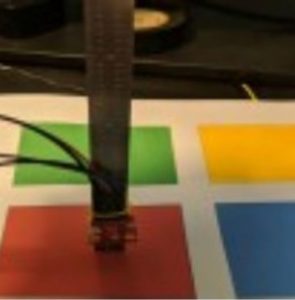
Figure 2: Set-up for measurements

Resources

  1. RGB Sensor Datasheet
  2. Light Sensor Code

Spring 2018 3DoT Hexy: Decision of Movement Mechanism

By: Eduardo De La Cruz (Project Manager and Manufacturing Engineer)

Approved by: Miguel Garcia (Quality Assurance)

Table of Contents

Introduction

     Taking into account the level 1 requirement of using only 2 micro motors to drive the movement of the robot, and by using designs from previous semesters as a reference. We as engineers had to determine the most optimal mechanism that would take full advantage of the 2 micro motors. References, such as that of  Spring 2016: 3DoT Spider-Bot Mechanism Research, pretty much covered the most promising designs to implement using 2 motors. However, we decided to focus more on the two models that were successfully built in the past: the Klann Linkage mechanism of Spring 2017’s Spiderbot, and the Hex Bug 2 mechanism Spring 2016. The goal we wish to accomplish by picking from the former or the latter is to:  reduce the amount of time invested in researching new designs, increase the probability of success, and invest more time building on improving existing designs.  

Related Requirements

  • To keep cost down, and keep a toy aspect , the robot shall use only 2 micro motors to drive the movement of the robot.
  • The robot will need to navigate remotely through a custom built maze (built by AoSa image), memorize the path it took, start over, and autonomously travel through the path it took.
  • The spiderbot shall have an allocated budget of $250, however to compete with the existing robot toy market we shall try to minimize the cost of production as much as possible.  
  • In order to minimize manufacturing cost, and packaging cost the robot shall be able to be constructed from subassemblies within 10 minutes.
  • For quick production of the prototype, the preliminary project shall be restricted to six hours of total printing time with a 2 hours limit for each single print.

Design 1: Spring 2017 SpiderBot, Klann Linkage Mechanism

Figure 1: Klenn Linkage Mechanism 

     Eight legged Klenn linkage spiderbots follows a 4 inner and 4 outer rule for stability.  This means that the spider will always have 4 points of contact: Case 1: outer legs lift and inner legs thrust, and Case 2: inner legs lift and outer legs thrust.

Pros:

  • Parts can be fabricated using laser cutter, reducing our 3D print times
  • Design will have 8 legs like an actual spider due to the need of bilateral symmetry
  • Design can be implemented using 2 motors
  • Can turn in place if programmed correctly

Cons:

  • A lot of parts will increase weight of the robot
  • The width of the robot will need to increase in order to fit 3DoT board and all components in the middle.  


A lot of resources on this model can be found online. Below are links to a couple of useful references on the Klann Linkage mechanism.  

  1. How it works
  2. Two Motor controlled Klann Linkage mechanism that can turn
  3. Going over objects
  4. Movement Dynamics
  5. Sample model built from start to finish


Design 2: Spring 2016 3DoT David, Hex Bug 2 Mechanism


Figure 2: Hex Bug Mechanism


This design can be accomplished using a cam system and by configuring the legs to move either as:

Shown above:

Case 1: Outer 4 legs lift, inner 2 legs thrust

Case 2: Inner 2 legs lift, Outer 4 legs thrust.

Design requires small lift height, in order to reduce time outer legs remain of the ground for stability.


Or:

can be reconfigured by adjusting the position of the legs on the gears to follow a tripod motion(as shown below).

Figure 3: Tripod Movement 

This was what Spring 2016s 3DoT David design had to do, click here.


Pros:

  • Design looks simple, not as many parts compared to Klenn linkage model
  • Can be designed to be small and compact because 3DoT board and other components can be placed over the mechanism without interfering leg movement .
  • Can turn if properly programmed, as demonstrated in the Spring 2016 video.
  • Can be driven using only 2 motors  
  • A lot of components can be made with either 3D or laser cutter.
  • Uses only 6 legs which reduces weight and cost of manufacturing.

Cons:

  • Leg to floor clearance during lift will be small, therefore, won’t be able to go over big objects


Resources:

  1. https://www.arxterra.com/spring-2016-3dot-spider-mechanism-research/
  2. http://robotics.hobbizine.com/knexapod.html

Final Design Decision

     Having had studied both design more in depth we decided that implementing the Hex Bug 2 design was the way to go. The Hex Bug 2 design takes advantage of gears configured as a cam system to provide sufficient torque to the legs for movement. This will reduce amount of 3D components needed since we will most likely be able to purchase gear set from an online retailer. Also this design only requires 6 legs meaning we will have less weight and less 3D printed parts to worry about. The only components that will most likely need to be 3D printed will be the femurs, and tibias. The chassis will most likely be laser cut. Since we need to fit the robot in small maze rooms, current maze rooms are  3’’x3’’, the Hex Bug 2 design allows us to make everything small and compact because we can place the 3DoT board and other components on a platform over the gear mechanism without interfering leg movement. The issue of floor clearance during lift won’t be an issue because going over objects is not a mission requirement.  


Spring 2018 3DoT Hexy: Improving 3DoT David Design

By: Eduardo De La Cruz (Project Manager and Manufacturing Engineer)

Approved by: Miguel Garcia (Quality Assurance)

Table of Contents

Introduction

     Since we decided to model 3DoT Hexy of Spring 2016’s 3DoT David, Prof. Hill recommended that we get in contact with the owner of 3DoT David to have access to the robot. Luckily, we were able to get in touch with the owner and were permitted to use the robot as a reference. From 3DoT David, we have learned a lot about: movement dynamics, overall dimensions, and weakest points in the structural design. In this blog post we will highlight the weakest points in the structural design of 3DoT David and provide solution that will be implemented in our design of 3DoT Hexy.

Related Requirements

  1. In order to minimize manufacturing cost, and packaging cost the robot shall be able to be constructed from subassemblies within 10 minutes
  2. For quick production of the prototype, the preliminary project shall be restricted to six hours of total printing time with a 2 hours limit for each single print
  3. The robot shall be designed in such a way that there are no dangling or exposed wires and the final fabrication is pleasing to the customer
  4. To keep cost down, and keep as a toy aspect , the robot shall use only 2 micro motors to drive the movement of the robot.
  5. The spiderbot shall have an allocated budget of $250, however to compete with the existing robot toy market we shall try to minimize the cost of production as much as possible.

Gear Capture System

     According to Chris (one of the engineers behind 3DoT David) 3DoT David’s cam system has a tendency of “gear popping”. This means that at high speeds the gears tied to the shafts slip off. To solve this problem the 3DoT David team relied on melting the tips of the shafts to prevent the gears from lifting. This also was a problem for the gears tied to the motors which could not rely on the previous solutions do to having a steel shaft. This solution solved the gear popping problem, however, it complicates the mission task involving assembly and disassembly. Below are images of how it looks:

Figure 1: Old gear capture design

Caps for gear shafts

Figure 2: Gear Capture solution

      To solve this problem we decided to use caps obtained online from a different gear set. The caps have a diameter of 3.2 mm which will be the diameter of the shafts we will use in order to ensure we have a tight fit without heating or gluing. This will make our cam system easier to assemble and disassemble.


Top shaft to prevent gear tied to motor from popping:

Figure 3: Old design: Nothing prevents the gear from popping off

Figure 4: Gear capture solution for driving gears

We will incorporate a shaft positioned over the driving gears that will be part of the 3D print of the top panel. This will keep the driving gear from coming off.

Gear to motor shaft connection

     3DoT David relied on gears that have a bore greater in diameter than the shaft diameter of the motors. The solution the 3DoT David team used to solve this problem was to insert a piece of a pen tube into the bore to provide a tight fit. The problem with this solutions is that there is no real mechanism that locks the gear to the shaft to prevent the gear from slipping from the shaft.

Figure 5: Old driving gears Motor shaft held to gear bore via the use of a cut piece of pen tubing.   

Figure 6: New driving gears 

     The motor shaft has a D shaped shaft, therefore using a gear with a D shape bore would lock the gear to the motor shaft. Luckily, our manufacturing engineer was able to find gears that have the 10 mm pitch diameter for our driving gears with a smaller bore, as shown above. This means that we can cut out the D shape using a dremel tool or other precision cutting tool.

Lift Mechanism

     3DoT David’s Lifting mechanism works well in thrusting and lifting the spider forward, however, the amount of lift of the current design is proportional to the length of the femurs. Since we want to reduce the overall width of our robot (to give it a better aspect ratio relative to a 4”x 4”  maze room),  figuring out a way to reduce the length of femurs while providing an acceptable amount of lift is desirable. 


Figure 7: Old leg design, note: units = cm

Solution:

     We decided that integrating the lift mechanism into the femurs of the legs would give us more control over the lift angle (since it will be based on the angle of the contour we define), as well as reduces the width of the robot since femur lengths can be reduced and will eliminate the need of the protruding lift mechanism. As an added extra, we also expect to see reduced 3D print times for the femurs.


     Our solution involves re-designing the femurs and the base to have a guide that will increment the angle of the femur as the femur rotates outward, providing lift. How it works:

Figure 8: Gear-to-Femur relation

     At point A the femur should be touching the floor and preparing for thrust. At point B, the femur begins ascending. At point C the femur is at its peak lift. At point D, femur is descending.This solution enables us to control the lift of the legs based on the angles of the femur contour. The guide that the femurs will follow will also have an angle to provide a smooth transition from point A to point C. As shown below:


Figure  9: New leg design 

     As can be seen above, the length the leg extends is 31.69 mm from the chassis, compared to 3DoT david’s 38mm leg extensions our leg design will reduce the overall width of the robot by 2*(38mm – 31.69mm) = 12.62mm. Our legs will have a lift distance of 5.56 mm which is 1.24mm less than 3DoT David Design. Also note, the top panel will have a protrusion that will keep the legs down when they are in there innermost point to keep them grounded as can be seen by the image above in the upper left corner. The height of our robot will be 28.28mm vs 38.1mm therefore our design will be 9.82mm lower meaning we should have a better reading for our sensors.

     Below are the calculations for our leg’s profile. Note, calculations for determining our leg profile were obtained from Spring 2016 3DoT David Leg Movement Angle Study.  

Circumference of femur tied to gear:  

C = 41.54 mm

Initial Lift do to inner contours:

7.89 deg – 3.59 deg = 4.3 deg

sin(4.3) = x/41.54    

x  = 3.12 mm

Final Lift Obtained = 11.92 deg

41.54 mm * sin(11.92 deg) = 8.58 mm

8.58 mm – 3.12 mm = 5.46 mm of lift of the ground


From our actual results, we can see that our design is .1 mm of the actual Lift.

If we wished to modify the height clearance of our design we would just change the value of the initial lift by changing the angle of the leg contours.

Leg Joints

      3DoT David’s leg joints where not a pretty sight to the eye. Since the design relied on a single contact point for the femur to tibia joint, 3DoT’s joints would loosen and become flimsy as the robot walked. The solution the 3DoT david engineers had was hot gluing the joints to make them stick together better (as shown below). However, this beats the purpose of the assembly and disassembly portion of the mission. To solve this problem we decided to redesign the leg joints to have more contact points.


Figure 10: Old legs and femurs 


Figure 11: New leg design

     By implementing this design, we had to redesign the tibias to give the joints 5 contact points. This will make the joint more sturdy. To prevent the joint from being a flexible joint, we will thread the hole the hole shown in the image above and insert a screw across to prevent the joint from moving the femur and tibia.

Wire Management

Purpose: Provide a path for wires from top panel to bottom panel that does not protrude out of the robot or interferes with cam movement.


Figure 12: Old design -Wires are wrapped in electrical tape and are susceptible to interfere with gear rotation.


Figure 13: New design

      Wires will have an isolated passage from top to bottom panel through two different apertures. Both holes will will have an 8 mm diameter opening giving plenty of space for all wires that will be connected to components on the underside of Hexy.  

Redesigning top and bottom panel

      We will be re-designing the top and bottom panel to accommodate new design changes made from old design review. We will also take this opportunity to give Hexy a unique appearance different from that of 3DoT David, and try to improve on reducing 3D print times.


Figure 14: Old design

Figure 15: New Design

      For the bottom panel we will fit gear lift guides into the chassis instead of having them stick out like in 3DoT David’s design (as explained in the lift mechanism section). We will extrude cut patterns in top and bottom panel to reduce 3D print times while at the same time giving our design a symmetric and appealing view. Top and bottom panel will have holes for the wire management and for the driving motor connection. The design will have more holes upon determination of the position of the custom PCB board, battery, and 3DoT board


Adding Washers

Figure 16: Adding washers 

     3DoT David didn’t see the need of adding washers to reduce friction, however we will incorporate washers along with grease in order to reduce friction between the gears and the chassis.


References

  1. https://www.arxterra.com/spring-2016-3dot-david-design-innovation/
  2. https://www.arxterra.com/3dot-david-rapid-gear-instability/
  3. https://www.arxterra.com/3dot-david-rapid-joint-connection-between-gear-and-leg/
  4. https://www.arxterra.com/3dot-david-leg-movement-angle-study/

Spring 2018 3DoT Hexy: 3D Print Times

By: Raymundo Lopez-Santiago (Mission,Systems, and Testing)

Verified by: Eduardo De La Cruz (Project Manager and Manufacturing Engineer)

Approved by: Miguel Garcia (Quality Assurance)


Update: 04/17/18

After the first protype, the design was changed accordingly to fix issues identified from testing the robot (under stress). The new design has been sent to Ridwan and we are currently waiting for a response. A new table with the 3D print times will be updated later.


Introduction    

This blog post covers the overall 3D print time for parts used in the 3DoT Hexy robot. Eduardo De La Cruz (Project Manager/Manufacturing Engineer) has made a sketch and model for 3DoT Hexy in Solidworks. A preliminary 3D print time for 3DoT Hexy is determined using a 3D Print quote from the Long Beach Makers Society and Ridwan. The quote is for using PLA/ABS material. In Fig.1, print times for each part are shown as well as the total print time for all parts using the Long Beach Makers Society’s quote. In Fig.2, print times for each part are shown as well as the total print time for all parts using Ridwan’s quote.  As defined in the core level 2 requirements, 3D printing time shall not exceed the 6-hour limit. Each part should also not exceed a 2-hour limit of printing. At this moment we are planning to 3D print most of the parts needed in the project. We are not including any PCB housing in this print time estimate. The total print time estimated from the Long Beach Makers Society quote with the current design is 6.8 hours which exceeds the total 3D print 6-hour limit requirement. Only one part exceeds the 2-hour limit of 3D printing requirement per part and that is the bottom plate. Our initial plan to tackle both these issues was to pursue an alternative design to reduce the print time for the bottom plate and to manufacture the top plate using laser cutting instead of 3D printing which will reduce our total print time to 4.8 hours. After requesting a quote from Ridwan, we no longer needed to change our project design since the total 3D print times quoted for this project reduced to 5 hours which meets the total 3D print requirement limit. This quote also states that the 2-hour limit of 3D printing requirement per part is not exceeded.


Related requirements:

Level 1 Requirements:

C-11:

For quick production of the prototype, the preliminary project shall be restricted to six hours of total printing time with a two hour limit for each single print.

Level 2 Requirements

L2-5:

The robot shall use 3D printed chassis and legs. This follows from the project level requirement about using 3D printed parts.

L2-5a:

The robot shall use PLA or ABS filament in the fabrication of the chassis and legs. This will minimize the mass of the robot, while at the same time being strong enough to hold its weight.


Fig.1: 3D print time estimate based on Long Beach Makers Society’s quote


Fig.2: 3D print time estimate based on Ridwan’s quote


Conclusion

To further get ahead on this project, we went ahead and used the 3D printing services from the Long Beach Makers Society for our prototype due to Ridwan taking longer to respond with the 3D print quote. We plan on using Ridwan’s 3D printing services for our final project print.


References

  1. https://docs.google.com/document/d/1GCPoru2ZqR_VMB8tJ2FTlfe8vI3Ci1x_8kVdWjqsFGM/edit?usp=sharing

Spring 2017 SpiderBot : Firmware Blog Post

By Shaun Pasoz – Electronics & Control Engineer

Introduction

While waiting for the breakout boards to come in the mail, to make the best use of time the E&C division manager tasked us with coding quizzes. One of the quiz questions involved controlling the TB6612FNG motor driver using a microcontroller such as the Arduino UNO. Below is the snippet of code submitted for that quiz question along with the comments:

In order to allow easy calling of the functions for the MST engineer the moveIt() function was itemized into corresponding functions as follows: a forward move, backward move, left turn, and right turn. An example of the forward() function is demonstrated below:

This code displayed above allows for control of two motors by utilizing four digital pins and two PWM pins from the microcontroller all from the same function. From here the next step was to include the code to control the third motor that will be controlling the winch.

Since the 3DoT only has pins available for two motors, it was necessary that the third motor be controlled via I2C. After doing some research it became evident that the Adafruit Motor Shield V2 used the same primary ICs as our PCB. To avoid writing code to manually control the I2C protocol the Adafruit Motor Shield library was used. The following snippets of code demonstrates our implementation of the Adafruit Motor Shield library:

Conclusion

To summarize, the motor shield object is instantiated using the Adafruit library with an address of 0x60. Motor 1 is then instantiated (since our project only needed one motor to be controlled only one instance of the object is instantiated), where the logic pins AIN1, AIN2 and PWMA from the TB6612FNG IC is connected to PWM pins 0, 1, and 2 on the PCA9685 chip. In order to allow for this the Adafruit library .cpp file was changed such that AFMS.getMotor(1) corresponds to PWM pins 0, 1, and 2.

The object is then began in the setup function and STBY pin on the TB6612FNG IC is brought HIGH by setting PWM pin 15 to a 100% duty cycle. Furthermore, the winch motor is set to full speed since the system utilizes 3.3V to power the motor, full speed is adequate for all instances of the winch motor control. Lastly, the equivalent move function of the winch motor is itemized in a function, called goUp(), to easily be called by the MST engineer when programming Bluetooth communication.

Spring 2017 SpiderBot : Prototyping Blog Post

By Shaun Pasoz – Electronics & Control Engineer

Introduction

Before sending out the PCB design for production, it is necessary to prototype the design using breakout boards and through-hole components. This is a necessary step to test the components in combination with the code and make sure the design works. The purpose of our PCB is to allow control of a third DC motor using the 3DoT. Our design utilizes two IC’s: the TB6612FNG manufactured by Toshiba, and the PCA9685 from NXP Semiconductors.

The TB6612FNG is a dual H-bridge motor driver. It will be used in our PCB design to control the third DC motor. The pins utilized on the motor driver will be VM, VCC, AIN1, AIN2, PWMA, STBY, AOUT1, and AOUT2. The PCA9685 is an I2C compatible 12-bit PWM driver. Since the 3DoT provides no PWM enabled digital pins, the component is necessary in the PCB design to provide PWM to the motor driver. The extraneous PWM pins will be used as a digital signal to control the motor driver.

Seen below is a Fritzing diagram of our design alongside a picture of the actual implementation:

Figure 1: Breakout Board Fritzing Diagram


Figure 2: Image of Implementation of Breakout Boards

In an effort to avoid soldering and de-soldering leads to the breakout boards, the implementation is not as clean. The implementation also shows that the design can easily be powered from a separate power supply; in this case, a 9V battery.

Update:

Although the design works using breakout boards. When implemented on a PCB, the PCB did not work. This could be due to a couple reasons. One, it’s possible the IC’s got damaged in making the PCB as it was not built in an ESD safe lab. Two, it’s possible that there was a manufacturing error such as traces being placed too closely together, or traces poor insulation of the traces. The second choice is the suspected problem as we tried making three different boards, using new IC’s and testing both ceramic and tantalum capacitors.


Spring 2017 – SpiderBot Project Summary

Table of Contents

Project Overview

Executive Summary

By Nicholas Jacobs – PM

The purpose of SpiderBot is to make an inexpensive, fun toy that can walk, turn, launch a grappling hook, and raise/lower itself to/from a predetermined height. While anchored, SpiderBot will provide a live video feed to the Arxterra Control Panel.

System Design

By Jefferson Fuentes – MST

SpiderBot consists of the 3DOT controller board based around Atmel’s 32U4. 3DOT also incorporates the TB6612F Dual Motor driver that drive two DC motors that enable SpiderBot to walk. SpiderBot also has a custom built grappling  hook that is launched under rubber-band tension. Once the grappling hook anchors to a fixed position the custom made winch motor assembly hoists SpiderBot to an elevated position. The 3DOT board can only drive the motors meant for walking, the custom PCB incorporates another TB6612F to drive the winch motor, and a PCA9685 PWM Expander that enables the custom PCB to communicate with the 3DOT board via I2C. To see our System Block Diagram go here.

Subsystem Design

Experimental Results

By Nicholas Jacobs – PM

At the onset of our design,  multiple trade off studies to determine what parts are required to complete our requirements. Our material trade-off study explored SpiderBot’s possible composition, while the motor trade-off study  looked at possible DC motors that could best meet the customer requirements. Once the proper DC motors was picked and ordered, we conducted a motor torque test to verify that the chosen motors were up to the task. We also conducted an experiment that determined the most effective way to suppress DC motor noise generated by the commutators switching polarities.   Lastly, since SpiderBot’s purpose was to provide a live video feed to the Arxterra Control Panel from an elevated position, we had to determine what reliable size maze could be covered with the phone being used. The experimental steps can be found here.

Interface Definition

By Jefferson Fuentes -MST

Interface definitions are used to determine the connections within the project.  The most crucial component, the ATmega32u, is the the brains of the project and process all commands.  Interface definitions for the the custom PCB are also included, showing how to connect it all to allow for proper function.The final, most updated description that explains the the inner workings and connections for the 3DOT controller, and the custom PCB  can be found here.

Mission Command and Control

By Jefferson Fuentes -MST

One requirement stated that SpiderBot is to be controlled by the Axterra App via a bluetooth connection. The Missions System and test Engineer’s job was to configure any custom command and telemetry decoding and encoding schemes that were necessary for SpideBot’s mission. Instructions, software block diagram, Arduino code, and  a detailed description the Arxterra Control Panel set-up can be found  here.

Electronics Design

By Shaun Pasoz – E&C

The motors that drive SpiderBot’s legs were initially GM3 DC motors. However the way they were mounted and the weight they had posed problems. Instead we settled on SparkFun’s MicroGear motors for they’re size, weight, low stall current, and very high torque output.  Pololu’s Microgear Motors.

Another capability that SpiderBot had was to launch our a grappling hook remotely via the Arxterra App. This was done by controlling a 3.3 volt servo from the 3Dot board. Since the grappling system is rubber-band actuated the servo unlatches a sear-style catch that allows the grappling hook to launch. Additional information can be found here click on 3.3volt_servo.

Firmware

By Shaun Pasoz – E&C

Firmware for controlling the 3DOT, custom PCB, and 3 DC motors, along can be found here.

PCB Schematic

By Shaun Pazos – E&C

Our custom PCB incorporated an additional TB6612F motor driver to drive our winch motor that allowed for SpiderBot to climb. Also on our custom PCB is a PCA9685 PWM Expander and its main purpose was to relay data packets from the 3DOT controller to our custom PCB via I2C. Additional information can be found here click on Custom_PCB_Chips.

PCB Layout

By Daniel Matias – MFG

More information can be found on our Custom PCB blog post after it had been built and tested. Unfortunately, only briefly did the custom PCB work. It will forever remain a mystery as to why. Additional pictures and other resources can be found here.

Hardware Design

By Daniel Matias – MFG

SpiderBot was based off the TerrSpider Instructable. The first build of SPiderBot consisted entirely of 1/4 inch acrylic. This caused SpiderBot to have a naked weight of 800 grams. The customer rejected this design and required that SpiderBot’s size be reduced. The first build was a costly one too, you can read all about it in our lessons learned blog post.

After the Critical Design Review SpiderBot was reduced by 25%. This resulted in a more streamlined design, and drastically reduced SpiderBot’s weight. All SolidWorks files and animations can be found here.

It’s amazing the ideas one can find on Youtube.  Our winch design is slight modification of a Westimation Miniature Winch . This design is desireable because of its size and torque.


Verification & Validation Test Overview

By Jefferson Fuentes -MST

Spiderbot was only tasked with doing a verification matrix this semester.  It consists of all requirements, testing procedures, and outcomes.  The detailed plan explaining how all tests were conducted can be found here.

Project Status

Power Allocation

By Jefferson Fuentes -MST

Power report should ideally be three separate reports denoting all power allocations on the project, Battery, 3DoT, and custom PCB.  Each power report must include the max, min, and average  power consumptions.  This data will ensure proper power allocation to project, as well as expose any over/under power supplied.

Mass Allocation

By Jefferson Fuentes -MST

Spiderbots resource reports consist of cost, mass, and power allocations.  Mass is the sum of all components on project minus the phone.  The total mass is what the DC motors, movements and winch, must be able to provide power and torque to in order to move.

Cost Report

By Nicholas Jacobs – PM

As we mentioned in our lessons learned blog post,  the first build of SpiderBot was a costly one. The laser cutting for Build 1 consumed ~42% of ur initial budget. To look at our cost breakdown click here. 

Updated Schedule

By – Nicholas Jacobs – PM

Keeping and adhering to a strict schedule is very important, especially in the first 6 weeks of the class. Once a design has been chosen and approved by the customer task your manufacturing engineer to start laser cutting or printing. The project manager and systems engineer should begin developing level 1 and level 2 requirements based on the Program Objective and Mission Profile.

If your laptop or desktop screen has a 3200 X 1800 resolution then ProjectLibre is NOT the scheduling software for you. I would suggest using Microsoft Scheduler instead.

Here is our top level and subsystems semester schedule. The top level schedule covers the tasks that, if not completed, will result in an incomplete or failed project. The subsystems schedule is a specific breakdown of tasks by division. Keeping track of this and updating is critical for mission accomplishment.

Final Thoughts

By Nicholas Jacobs – PM

During the last 4-5 weeks of the semester problems were discovered that could be solved with the remaining time of the semester. The walking mechanism never 100% worked all the time. During a revolution of the leg linkage is a point where the drive gear pinches one of the driven gears making the motor stall.   Luckily the motors run at 5 volts. Most of the time this was enough to power through friction points and offset hand drilled shaft holes. As the crow flies looking down at SpiderBot from above, you’ll see that the SparkFun MicroGear motors aren’t normal to the side panels they engage with. I believe that if this were fixed, this would correctly align the drive gear to the two driven gears.

One misfortune was the custom PCB. It not working was a surprise because of the number of revisions we had along with the number of eyes who reviewed it- I was sure it would be plug and play. Looking back at the PCB layout, I would have added a power and ground plane. This will cut down on noise by eliminating the number of open loop antennas created by traces.

One bigger regret I have for SpiderBot is not taking the time to research the parameters of the Simulink Winch Model. Calculating the parameters necessary for this model could have influenced our winch motor selection or helped us better design a better gear ratio to increase speed. At a bare minimum we would have been the only group to have any kind of Simulink model for any subsystem of our project.The winch built for SpiderBot didn’t have a brake and was deleted from the model.

This semester’s SpiderBot was successful for two reasons. The first being that we decided to go with an Instructables Project that PROVIDES DESIGN FILES!!!!!!!!!!! ( Be Careful ) Once we decided on the TerraSpider concept, already having the .dxf files allowed us to print and produce our strawman design the following week. Remember our jobs as engineers is to be more effective rather than original, in this case starting off with something already done saved countless hours of unnecessary design time. Strawman design is another name for a proof of concept or first draft, but is ultimately something that undergoes the iterative process-which undergoes continual improvements and modifications which slowly morphs into a robust, well made end product.  The second reason is that we kept our self in a small box, otherwise know and KISS- Keep it simple, stupid. We set very REALISTIC and SIMPLE goals that, we as a team felt were actually realizable – walk, turn, turn a servo and climb.

Resources

SpiderBot Video

CDR 

PDR

Project Libre (with Excel Burndown file)

Verification and Validation documents

Solidworks File

Fritzing Files 

EagleCAD files (zip folder) Linked to in Electronics Design Blog Post

Arduino and/or C++ Code (zip folder) Linked to in Software Design Blog Post

Complete Bill of Materials (BOM)


Spring 2017 SpiderBot – Custom PCB COMPLETED AND TESTED!!

By Nicholas Jacobs – Project Manager

Table of Contents

Introduction

The 3DOT controller is a minimalist board. It comes equipped with a two channel motor driver that drives SpiderBot’s two DC motors at 5 volts, leaving nothing to drive SpiderBot’s 3.3v winch motor. Our custom PCB incorporates an additional motor driver and PWM expander that enable I2C serial communication between the custom PCB and the 3DOT controller.

Requirement

SpiderBot shall incorporate a custom PCB. The PCB will consist of a PCA9685 PWM expander and TB6612FNG H-Bridge motor driver to drive a 6v Metal Gear dc winch motor at 3.3 volts.

Design Iterations

Despite shaving a lot of unnecessary weight off of SpiderBot, a problem still persisted. Operating the winch motor at 3.3 volts resulted in a 5 minute ascent time to the anchor point. After consulting with Shaun and Thomas, the E&C engineer and E&C division manager, I made the decision to run the winch motor at 5v which drastically improved the ascent time of SpiderBot. The only modification to the custom PCB was the addition of a 5 volt LDO.

When this design was presented to the customer, he rejected the idea of running the winch at 5v. He specified that there was no requirement in the Program Objective that prompted the need to run the winch motor at 5 volts- basically there is no need for SpiderBot to ascend fast. Hearing this, I pulled our PCB files in order to revert back to the winch being driven by 3.3 volts.

Once the design files were approved for fabrication, the Gerber files were created using the SparkFun CAM processor.  These files allowed for the PCB to be constructed,  allowed for the creation of the solder stencil, and solder paste from Osh Stencils. Osh Stencils has a very easy user interface to work with, the only gerber file that is need to create a stencil for your board is the .gtp file.

Bill of Material (BOM)

Eagle CAD has a ULP or User Language Program that will generate a complete list of materials used in either the schematic file or board file. Open Eagle CAD and the schematic of whatever BOM you want to create. In the taskbar enter BOM.ulp and press enter. If you get an error of some sort, just go to file -> Run ULP -> then select BOM. A window will pop up and under List Type select ‘parts’ and ‘file type’ select .csv, and save to well known location. This file type can be opened using Excel.

Open this .csv file from Excel, you may have to change the file type from ‘All Excel Files’ to ‘ All Files’ in order to see the .csv. When found double click to open. When this file loads it will look messy and Excel may ask you to save it as a different file type, maybe an .xls. To organize the data select the entire ‘A’ column and navigate to the Data tab, then under Data Tools click ‘Text to Columns’. When the window pops up make sure ‘Delimited’ is selected click next. Even though the file type is .CSV, which stands for ‘comma separated values’, in the delimiter section check the semicolon box. In the preview box below it, you’ll see the data begin to clean up. Click finish, and all your data should be organized.

Assembly and Soldering

Once the boards were received, plans were made to solder the components using a microwave oven, a solder stencil, and solder paste. The first step is to adhere the solder stencil over the PCB in such a way that only the SMD pads are exposed. This will allow for the solder paste to only be applied to the component pads.

Once the solder paste is applied, the components are very carefully placed in their respective spots on the PCB. Before placing in the oven, the oven was preheated to 300 degrees Fahrenheit. The board was then placed in the oven, allowing for a gradual temperature acclimation.   After about 90 seconds, the heat was increased to about 450 degrees Fahrenheit to melt the solder paste. Once the solder reflowed, the oven was turned off and the board was removed from the oven for cooling.


Testing

Code used to test PCB utilizes the Adafruit Motor Driver v2 library. Since the device communicates over I2C, the Wire.h library is also included.

The first step is to instantiate the motor shield object as seen on line 16. Since our PCA9685 IC has pin a5 pulled to Vcc, the address has been changed to 0x60.

After instantiating our motor shield object, we then need to tell the board which motor we are trying to drive, either motor 1 or 2. For testing, we have made two motor objects so that both motors can be tested.


Setup:

Start with Serial.begin(9600) so that we can output onto the serial console for debugging purposes.

AFMS.begin(); takes care of the I2C protocol such as Wire.begin, etc.

In order to be able to control the motor driver, the standby pin needs to be pulled high. This is done by using AFMS.setPin();

After, STBY has been enabled, we can now use the library to drive either motor by calling the object and speed function, and then calling the object and run function.

Example:

myMotor->setSpeed(255); //sets motor1 for full speed in our code.

myMotor->run(FORWARD); //tells motor 1 to run forward

Spring 2017 SpiderBot – Custom Commands Update

By Jefferson Fuentes – MST

Table of Contents

Requirements:

The Spring 2017 Spiderbot project, S-17 Spider, shall provide a live aerial video footage for end of semester game.  In addition, S-17 Spider, shall incorporate a grappling mechanism to elevate itself from the ground level.


Introduction:

The S-17 Spider features the ability to elevate itself off the ground through use of a grapple and winch system.  The purpose of this post is to provide an explanation of the Spring 2017 Spiderbot project, S-17 Spider, custom commands utilized in controlling project functions via the ArxRobot App.  The software block diagram (fig. 1) shows a layout of all functions used for control of project.

Figure 1 – Software Block Diagram


Commands:

The MOVE command is utilized to control the projects directional functions.  By sending individual commands to the two connected DC motors, each motor can spin clockwise or counterclockwise, allowing for desired direction.  

The LATCH command serves to control the single servo connected to 3DoT.  The servo is sent a signal to spin its full 180 degrees and release the grapple, hence the function name.

The WINCH command serves to control a single DC motor connected to the custom PCB via I2C.  Similar to the move command, a signal is sent to the DC motor to spin it clockwise or counterclockwise.   The motor serves to power a winch, which allows the project to elevate itself higher or lower.

The code for the custom commands is shown below.  The first step is initialization of the code (fig. 2), which includes all necessary files to run all functions denoted by #include <>.  The custom commands are then defined, #define, and given their address, 0xXX.  In S-17 Spider, we are using 3 custom commands which also needs to be declared in the following line.  The last few lines are the handlers.  Their purpose is to direct the incoming command to the appropriate function (custom command).  


Figure 2- Code Initialization


The parameter for all functions is 0 to 255, a byte.  This works wells with the MOVE command, which moves clockwise and counterclockwise.   The LATCH command controls the servo, which can only rotate 180 degrees.  To accommodate, 0-255 must be converted to 0-180.


ArxRobot Control:

The s-17 Spider uses the provided ArxRobot app for wireless control, via Bluetooth, of the project.  The three main function of the project are included (fig. 3) in the app layout.  For the S-17 Spider project all functions are in Boolean, meaning that either function is either on or off.  The winch function uses two Booleans to control the direction the motor spins.  The latch function controls the servo which turns the full 180 degrees one way or the other.  


Figure 3 – ArxRobot Layout