Final Project Document

By Kristine Abatay – Project Manager
      Matthew Clegg – Computer & Control Systems
      Simon Abatay – 3D Modeling & Manufacturing

Before signing off with the final document for Spiderbot, we would like to thank various members of the Robot Company in aiding with the completion of Spiderbot:

First off, we would like to thank David Gonzalez of last semester’s Hexapod project for his loan of Chop Suey for preliminary code practice.

We would like to thank Ali Etezadkhah of 3D Bioprinter and division manager of manufacturing, for allowing us use of his 3D printer for the class and for printing Spiderbot’s pieces in a timely fashion.

We would also like to thank Tommy Sanches of MC3 for his immense help in getting Spiderbot connected to Arxterra.

We would like to thank Elaine Doan of Biped for helping run tests and for guiding Spiderbot in the writing of requirements.

Finally, we would like to thank Vice President (Dr.) Larry Harmon for all of his hard work in posting countless blogs and grading presentations, despite his busy schedule.

THANKS!

A pdf file of the final document of Spiderbot can be downloaded here:

https://dl.dropboxusercontent.com/u/184627659/EE%20400D_Spiderbot_CDD.pdf

This is Project Spiderbot signing out.

Live Long and Prosper!

Spiderbot: Struggles Remembered and Suggestions

By Kristine Abatay – Project Manager
      Matthew Clegg – Computer & Control Systems
      Simon Abatay – 3D Printing  & Manufacturing

Following the mass lay-off of all members of the Robot Company for Spring 2014, we remember the numerous struggles faced by Spiderbot with the following video:

http://youtu.be/1e-2mCIpM-Y

Many improvements can be done to make future Spiderbots better machines.

For one thing, connection of Spiderbot to the Arxterra Android App can definitely be helped by possibly finding a forest-like route in a different location on campus. Many issues occurred on demonstration day during the race against Rover and Hexapod. Connection was constantly dropped when multiple projects were connected to the app in the particular race course area and perhaps a location with better wifi connection might remedy that issue.

A route with a more even terrain might be helpful in preventing damage to the gears of the servo motors, as was done with one of the servos from a rear leg of Spiderbot.

A convenient trick we learned from Tien Dang, Communications member of Hexapod, was that if, when taken apart, the servo motor shows gear damage, then the motor can easily be fixed by replacing the gear, which can most likely be purchased online. This is much cheaper than purchasing a whole new servo motor.

The damage was most likely done when testing Spiderbot in the race location prior to the race, when it encountered the various branches of the course.

As for manufacturing, the individual pieces can be improved to help Spiderbot’s overall performance. For one thing, the tibia side portions of Spiderbot’s tibia pieces can be shaved down. The pieces were extended mostly for aesthetics, so if they were shaved down to the same width as the servo motors in their particular orientation, then they should function just the same and be lighter in weight in the long run.

The base of Spiderbot was ultimately very dense, causing the stance of Spiderbot to be higher than it should have been in order to support the entire piece. A wider base most likely would have allowed for a lower position and therefore, a faster sweep of the legs. Research regarding a possible ratio between the base width and leg length should be done to achieve a faster speed.

In regards to the connections of the bracket pieces, the tibia pieces were molded in a manner that made it difficult for the screws to easily tread and lock into them. Because of this, epoxy was initially used, but after testing in the grass, it proved to be too weak of an adhesive. Loctite is recommended as a better adhesive alternative to insure secure connection. That, and testing in terrains aside from grass, since the grass most likely caused some wear and tear in the servo motors from the legs getting stuck.

Purchasing stronger servos would be a good alternative to increase the speed as well, but will ultimately rack up the cost of the final project. Another thing to keep in mind in regards to cost is that creating a mold to cast 3D pieces will require a lot of material, so the initial starting price for this project is already projected to be a couple hundred dollars, so mold and cast wisely.

Good luck to all future Robot Company Projects!

Spiderbot: The Final Video

By Kristine Abatay – Project Manager

With the demonstration of all projects having wrapped up, the final video for Spiderbot, created by yours truly, has dropped! The video can be viewed after clicking the following link:

http://youtu.be/5wJuN8XxtVk

Enjoy!

Project Burndown and Overview

By Kristine Abatay – Project Manager

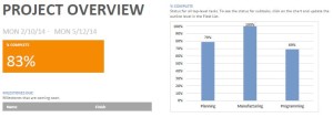
The following image displays the final overview of Spiderbot:

 Blog25_image1

Due to the incomplete state of some of the tasks originally assigned, Spiderbot is only 83% complete. The slack comes from the planning and programming portions of the progress of Spiderbot. Manufacturing is labeled at 100%, since, though not done in the timely fashion that was hoped for, Spiderbot’s design came out, for the most part, as planned.

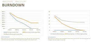
The burndown of the project can be seen in the charts below:

 Blog25_image2

I did not account for many of the issues causing delays that were encountered throughout the progress of this project, so the work and task burndown plots are steeper than they should have been. 

A Day at the Races

By Matthew Clegg – Computer & Control Systems

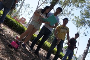
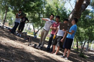
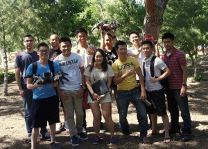
It all began earlier in the day. Group members Kristine Abatay, Simon Abatay and Matthew Clegg met early in a classroom, for a last second check to ensure everything on Spiderbot was working properly.  A couple of screws were tightened and the Android phone was connected properly to the Arxterra website. The group had lunch to prepare for the race. At around 2 o’clock, Spiderbot, Hexapod, and Rover met on the predetermined course.

SONY DSC

SONY DSC

There was a bit of nervousness coming from all the groups. Who would come out on top? Who would be showered with glory and accolades as the victor or who would crash and burn in failure and leave bitter and dejected? Negotiations quickly took place to shorten the course with less obstacles but this did not go through because the original course was outlined in the requirements and had to be the one all of the projects would race on.

SONY DSC

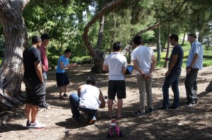
Both Spiderbot and Hexapod were fairly large, so having them all line up and race at the same time would have proven difficult. It was decided that each project would go individually and a time would be kept as it traversed the track.  All of the groups had difficulty at first establishing a connection due to Wi-Fi issues but it was all eventually settled by having only one project at a time connected to the Arxterra control panel.

SONY DSC

We (Spiderbot) got everything up and running and decided to go first. The first two steps started off well, but after that things quickly deteriorated. The pathway was on uneven ground, so with each step, Spiderbot slowly drifted to the left. Attempts to correct this did not fare well either. As it was turning, it lost footing, which caused it to collapse. It was picked up and set on course again. The next problem to arise was the servos. The rear right servo that causes the spider to lift its leg started making a horrible grinding noise with each lift. The weight of Spiderbot might have been too great for the servos to sustain for an extended period of time. At this point, it was decided to shut everything down to prevent further damage. Simon opened up the servo and found the gears inside to be busted.

The total distance traveled was roughly 6 feet at a time of around 3 minutes. Hexapod and Rover reached a further distance but did not have their share of issues. No project completed the full course. Spiderbot was defeated that day, but it was not a total loss. The knowledge learned from the track can be used by future projects for better planning and design. From the ashes, Spiderbot shall rise again like the phoenix.

SONY DSC

Here’s a link to a video of the exciting race day!:

http://youtu.be/XNUIfEWJOmY


Weight Resource Report

By Kristine Abatay – Project Manager
& Simon Abatay – 3D Modeling & Manufacturing

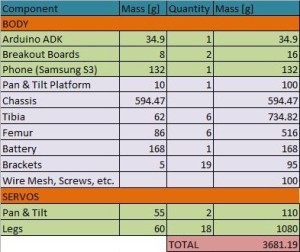
The following tables are the weight resource reports for Spiderbot.

This first table shows the various masses that we initially predicted. The masses for the parts that were 3D printed (Chassis, Femur, Tibia, Pan & Tilt) were taken from estimates provided by SolidWorks with the properly chosen materials.

 Blog23_image1

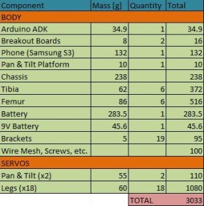
This second table is  the final weigh in of all of Spiderbot’s parts, with a slight estimate on the ‘Wire Mesh, Screws, etc.’ row.

 Blog23_image2

Ultimately, a majority of the parts weighed much less than what was predicted. The value that did increase was the femur portion, but that is understandable seeing as to how that particular piece was designed to hold two servo motors, so more weight is welcomed in that area.

Level 2 Requirements – Final Iteration

By Kristine Abatay – Project Manager
& Elaine Doan – Robot Company Systems Engineer

The following three requirements are the initial level 2 requirements that were introduced during the Spiderbot PDR:

1. In order to match the speed of the rover project while on a flat surface, the servo motors will need to move a distance covered by 60 degrees in 0.13 seconds and utilize a tripod gait – the walking style that will allow Spiderbot to move quickest, which will be implemented in the coding of Spiderbot.

This value was obtained using the following calculations done by our controls systems member, Matthew Clegg.

To try to estimate a possible speed for Spiderbot, he first calculated a velocity based on the speed of the servo motors. A servo’s rated speed is how fast, in seconds, the arm can move 60 degrees. To apply this to Spiderbot, he took into account the motion of the bot in a tripod gait. The gait is the specific sequence of leg movements executed when Spiderbot is in motion. An analysis of the different possible walking styles that Spiderbot is capable of can be found in the following blog post link from last semester’s Hexapod project: https://www.arxterra.com/hexapod-gait-description/. The study will show that the most efficient possible walking style that Spiderbot can use is the tripod gait.

These calculations can be found at the following link to a previous post, which lays out the calculations used to determine these values:

https://www.arxterra.com/speed-calculations-component-modification/

Test: Since this time value is so quick, measurement of this speed will require implementation of a video recording device and slow motion playback in a video editor. Code will be run through a breakout board and Arduino to a servo that will be placed on top of a protractor, which will be marked off to accurately measure 60 degrees. A digital stopwatch will be placed near the servo and will increment its time while the servo motor operates. A video of the motor will be captured and opened within a video editing program which will modify the video to play in slow motion. This way, the milliseconds portion of the watch will be easier to read and the time for the servo motion can be recorded.

2. In order to meet the safety requirement outlined by the level 1 requirements, Spiderbot will need to be constructed from materials that will prevent it from being labeled as a hazard. Avoidance of materials such as LiPO batteries in the Spiderbot design will help achieve this.

Test: According to the Injury and Illness Prevention Program for CSULB (found here: http://daf.csulb.edu/offices/ppfm/ehs/programs/iipp/#policy1), “All…hazard class scenarios shall also be immediately reported to SRMIS and each will be addressed on a case by case basis with the individual college or department manager”. If the final construction of Spiderbot does not garner the attention of SRMIS by falling under the category of one of its four hazard classifications, then Spiderbot will have met the safety requirement.

3. To meet the clearance specifications of 4 inches in height and 2.5 inches in width, Spiderbot’s 3D design will need to be at least 5 inches in height and 3 inches in width. The following design considerations were developed by Simon Abatay from manufacturing, to determine these value choices.

The femur length is chosen based off of reasonable servo specifications. Standard servo speeds from 0 to 60 degrees vary from 0.08 to 0.2 seconds. The femur length and servo speeds are critical for the spider to reach the speed requirement of 0.2003m/s.  Based off of calculations, if the femur length is chosen to be 5 inches, the servo must rotate from 0 to 60 degrees along its z-axis within 0.12 seconds. If the femur length is chosen to be 3.5 inches, the servo must rotate at a speed of 0.09 seconds. This relationship shows that the longer the femur, the greater the distance traveled, thus the slower the servo has to move. Realistically, it would be ideal to choose a femur length that is longer than 3.5 inches. This is because finding a servo that moves at a speed of at least 1.2 seconds under load is more realistic than finding a servo that moves at 0.09 seconds under the same load.

Test: These clearances will be checked within the SolidWorks. Once a complete leg and chassis design are made, the pieces can be connected in the program, and if the measurements done allow for the obstacle clearances, then this requirement will have been met.

This next list of additional level 2 requirements was written with minimal guidance from Robot Company’s Systems Engineer, Elaine Doan, who wrote the requirements for this semester’s Hexapod project, alongside Hexapod’s Computer Systems and Software member, Chau To:

4. In order for Spiderbot to receive commands from the Arxterra Android App, via the Arxterra Control Panel, the microcontroller used must have a USB host interface.

For this reason, an Arduino Uno – R3 will be used, which will allow for communication, but will not accommodate all of the servos that will be used for Spiderbot.

Test: Send a command to the Android smart phone being used by Spiderbot, using the Arxterra control panel, and if the command executed matches the command that was sent, then this requirement will have been verified.

5. The microcontroller used must also provide connections to accommodate pins to control 20 servo motors.

Since the Arduino Uno – R3 does not directly accommodate all 20 servo motors, two Adafruit 16-ch 12-bit servo drivers will be used to provide power to them.

Test: Connect the servo driver used, along with a servo motor, to the microcontroller chosen and run a basic Arduino command. If the command sent to the servo motor matches the action executed by the servo motor, then this requirement will have been verified.

6. In order for motion of Spiderbot to occur, its battery will need to supply at least 10800 mAH.

This value is an estimate that accounts for the 18 servos that will be used to control the legs of Spiderbot, which is where a majority of the current will be allocated. The value was obtained from testing of the Power HD servo motors, whose results can be found here:

https://www.arxterra.com/current-test-of-the-power-hd-high-torque-servo-1501-mg/

The maximum current that was drawn from the servo motors, using a supply of 6V, was 0.6A. Multiplying this value by 18 yields the 10800 mAh stated above. Of course, this value overshoots the true amount of current that will be used by Spiderbot, considering the fact that all of the servo motors will not be drawing their maximum current simultaneously.

Test: Connect Spiderbot to power and let it run. If it lasts for at least 1 hour, then this requirement will have been verified.


Initial Implementation of Arxterra Android App

By Matthew Clegg – Computer & Control Systems

With the final model of Spiderbot finally up and somewhat running, coding for communication between Spiderbot and the Arxterra control panel, via the Arxterra Android App has gone underway. With help from Tommy Sanchez of Robot Company’s MC3, I have managed to implement the code to enable communication with the control panel.

The following link is a video of basic movements available on the Arxterra control panel as applied to Spiderbot:

http://youtu.be/x4c4ajhPN9c

Prior to the time of recording, one of Spiderbot’s legs twisted so Spiderbot is placed on top of a toolbox for support, so movement has been shown in slow motion to give a better idea of what the actual Spiderbot movement is.

This link will lead to base instructions that were written to help with connection between the Arxterra Android App and Control Panel:

https://www.arxterra.com/news-and-events/

Cost Update

By Kristine Abatay – Project Manager

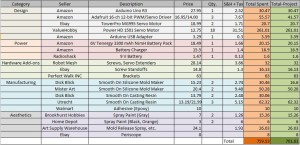
The following figure is a table of the total amount spent in creating the final model for Spiderbot:

Blog19_image1

Two total values are provided in the far right columns. The orange column projects the total amount that was spent in completing the overall project. The green column excludes any costs spent on material that was a result of experimentation. For example, the initial mold that was created for Spiderbot’s tibia piece was not used for the final tibia pieces, so its cost was removed from the final green column total. The same goes for some of the costs included in the orange column for casting resin material. There are three breakout boards included in the orange column costs because one of the boards was damaged, as mentioned in a previous blog post.

The items that are listed with two prices, separated by a backslash, indicate that two separate totals were paid for those components. In the case of the casting resin, our 3D modeling and manufacturing member, Simon Abatay, managed to find coupons and deals, so those materials purchased in-store were much cheaper in price. This route of purchasing smaller containers of the material in-store, was taken because purchasing everything in bulk online would have been too expensive and would have resulted in too much excess material.

The total cost came out to be much larger than expected (the expected total was somewhere in the $600 range), but many things were learned in doing so. Much more money was spent in the silicone mold maker material compared to last semester because the pieces used in this semester’s Spiderbot were more three-dimensional and voluminous by nature, so naturally, more material was required. An innovative method for producing casted pieces with less material was also found because so much money was spent to fund the experimentation portion of manufacturing, so maybe this grand, albeit scary, total was a good thing.  


Initial Code Implementation

By Matthew Clegg – Computer & Control Systems

With the assembly of Spiderbot about 80% complete, implementation of the code for its operation is finally being implemented. There have been many difficulties in Spiderbot’s operation. After several runs of the code, it seems Spiderbot is having difficulties with keeping its base off the ground. At this moment there is hope that this issue can be fixed with code, or that maybe there is not enough traction on the surface on which it is being tested.

A video of the first steps of the nearly-completely-assembled Spiderbot can be seen at the following link:

http://youtu.be/brh-NxkkgS8