Spiderbot Assembly

By Simon Abatay – 3D Modeling & Manufacturing

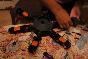
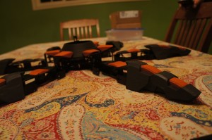
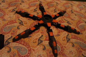
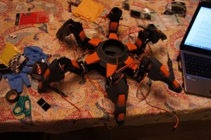
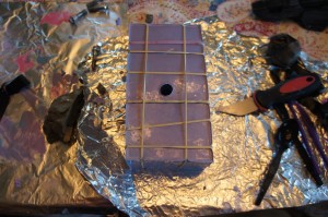
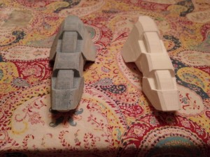
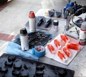
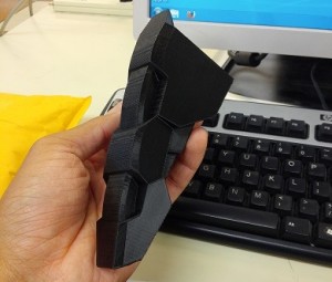
With the final parts obtained from manufacturer Ali Etezadkhah and the final components casted and cured, the body of Spiderbot was ready for painting. After all the parts were primed and painted, the final Spiderbot was assembled. The servos for the femur pieces had to be taken apart initially in order to place them securely into their designated holders. A combination of epoxy and small screws was used in order to hold the tibia pieces in place with the brackets connected to the femur pieces. Some components were held together with Velcro and double-sided tape until the final operational components could be placed into Spiderbot.

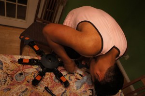
Below are images of the assembly of Spiderbot without the operational components and pan and tilt components.

 SONY DSC

SONY DSC

SONY DSC

SONY DSC 

SONY DSC


Modified Slush Casting Method

 By Simon Abatay – 3D Modeling & Manufacturing

After the mold is finished, it is time to cast the leg.

This method is a variation of roto-casting and is popular in the DIY prop making community.

(TheRPF)

http://www.therpf.com/f11/mold-making-slush-casting-whre-do-i-start-36457/

Materials:

  • 2-Piece mold
  • Smooth Cast 300 Part A and B
  • Rubber bands
  • Oil Based Clay
  • Liquid Dye
  • Plastic Cups
  • Mixing device

Process:

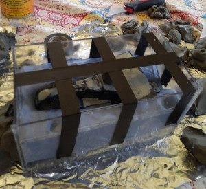
  1. Use rubber bands to hold the 2 piece mold together. Apply the rubber bands in both the horizontal and vertical direction of the mold.

    SONY DSC

  2. Pour equal amounts of the Smooth Cast 300 parts in 2 separate cups. Roughly about 2 – 3 ounces per.
  3. Pour both parts into the same plastic cup and stir well.
  4. Check both the color and viscosity of the mixture to make sure it is uniform throughout.
  5. Drop about 3 eye drops of liquid dye into the mixture and repeat step 4 after mixing.
  6. Pour the mixture into the mold.
  7. Lift the mold and move it side to side and in a circular motion. This will slush the mixture around so it will form along the sides of the mold.
  8. After about 2 minutes of casting you will see that the mixture will bubble. This bubbling is due to the dye and resin mixture.
  9. The mixture will then rise out of the mold where it was initially poured into.
  10. Using the clay, plug the hole so that the bubbling mixture doesn’t rise past the mold itself. This bubbling effect will fill the inside of the mold while keeping the desired shape and look.
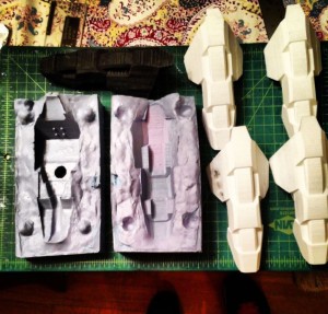
  11. After 15 Minutes, Pull the mold apart. What you are left with is a lighter version of the 3-D printed piece. The inside of the casted piece will mimic the honey comb effect of the 3-D part.

    Blog16_image2
    Blog16_image3

  12. Sand, prime, and paint to the desired color scheme, or keep it raw.

Blog16_image4

The following link is the process in video form:

https://www.youtube.com/watch?v=I57pOEQ6x_w&feature=youtu.be

Solutions to Wi-Fi connection issue

Members:
Vinh Khoa Ton: Biped team, Control & Image Processing
Tien Dang: Hexapod, Communication

Chau To: Hexapod, Computer systems & Software
Mevan Fernando: 3D Bio Printer, Sensors, Actuators & Powertrain
Robert Licari: Communication

Objective by Vinh Khoa Ton:

Hexapod team and Spiderbot team need to run their robots on a track field that does not support internet connection. Our team’s goal is to find a way for them to get access to the Wi-Fi connection so they could control their robots remotely using Arxterra control panel. The solution should have minimum cost. The internet connection should be stable (no disconnection or lost signal) with enough bandwidth for at least two mobile phones and two laptops, and the range of Wi-Fi is enough to cover the track field.

Some considered solutions

Wi-Fi Antenna by Tien Dang

http://arxterra.com/wifi-antenna/

Wi-Fi Range Extender by Chau To

http://arxterra.com/wi-fi-range-extender/

Buy a Wi-Fi/4G access point by Vinh Khoa Ton

http://arxterra.com/buy-a-wi-fi4g-access-point/

Main solution – Smart Phone Hotspot by Mevan Fernando and Robert Licari

http://arxterra.com/smart-phone-hotspot/

Conclusion by Robert Licari

In simplest words, the best and easiest WLAN (Wireless Local Area Network) that can be produced in our testing grounds is the smartphone hotspot capability that is virtually a company standard. In an area that demands the use of a Wi-Fi connection in this manner, we have verified that this solution covers our requirements of speed, cost, bandwidth, and range.


Wi-Fi Range Extender

By Chau To

Introduction:

Wi-Fi extender or Wi-Fi booster is a device that picks up a wireless signal and then rebroadcasts that signal. It acts as a second access point for other devices to connect to. The range of a typical Wi-Fi extender is around 300ft. Some expensive Wi-Fi boosters can achieve a range of around 450ft.

Pros and Cons:

Pros:

1. The Wi-Fi extender can be a solution to solve the Wi-Fi problem at the testing point. It can be used as a second access point between the building and the test place.

2. It is very easy to set up. There are 3 steps to set up a Wi-Fi extender. First, connect to the laptop via DSL cable. Second, launch the set-up GUI. Third choose the wi-fi signal to extend.

3. It is easy to find: Fry’s, Best Buy, online etc.

4. Quality and cost can be reviewed at this website:

http://wi-fi-booster-review.toptenreviews.com/

Cons:

1. The Wi-Fi extender always experiences 20%-50% throughput loss (the data rate loss) because it has to receive and then transmit data. As a result, the efficiency of the Wi-Fi extender is not that good. The amount of data used by Arterxa is very large because of the camera video streaming, so the efficiency of the Wi-Fi extender would affect the performance of the robot.

2. Wi-Fi extender is not very reliable. The connection is very bad especially for outdoor because of interference.

3. High-quality Wi-Fi extender can be expensive.

Testing:

Use the Diamond WR300NR Wi-Fi Extender (in the figure) to see if it can solve the Wi-Fi problem. At the test site, we experienced many problems:

1. The Wi-Fi extender used the school’s Wi-Fi signal beachnet+ and boost that signal over the parking to the test site. The best place to place the Wi-Fi extender is around 50ft outside of the building so that it could performed at max efficiency. However, the test site and the building is 500ft apart, the Wi-Fi extender couldn’t boost the Wi-Fi signal to the test area.

2. Interference is another major problem. Although the smart phone we used to connect to Wi-Fi was in the range covered by the Wi-Fi extender, the speed was very slow. And it lost connection all the time.

3. Power could be a problem because the Wi-Fi extender connected to 120V AC power from the wall, so we had to use a long cable to connect from the building to the parking lot.

Conclusion:

The Wi-Fi extender is not a good solution for the WIFI problem because of the range and the outdoor interference. A better quality and more expensive


Smart Phone Hotspot

By Mevan Fernando and Robert Licari

Introduction by Mevan Fernando

Tethering is when a smartphone is turned into a mobile Wi-Fi hotspot and its 3G/4G data connection is shared. Once tethering is turned on in the smartphone, any device with a wireless connection can connect to the internet via the smartphone’s connection.

Procedure by Mevan Fernando

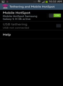
The steps taken to connect to the Wi-Fi hotspot and connection to the Arxterra Control Panel on the mobile data connection is shown below. The mobile phone used was a Samsung Galaxy S3 and the test was run at the site of the route where the robot will navigate. The following set up tutorial is performed with an android phone (Samsung Galaxy S3).

Step 1 – Click on the Mobile Hotspot app on the phone

step1

Step 2 – Turn on Mobile Hotspot
step2

Step 3 – Connect to the mobile data connection using any device with wireless connectivity (password required)
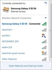
step3

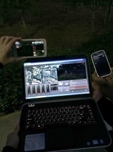
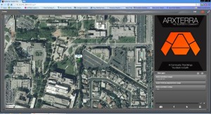
Step 4 – Log in to the Arxterra Control Panel
step4

Step 5 – Start control your robot
step5

Discussion by Robert Licari

Wireless provider

The wireless provider is a simple matter considering that most, if not all, of our employees carry a cellular phone and an almost equivalent number of employees carry smartphones. Taking this into consideration, we can simply utilize the sources provided by different service providers to view their coverage maps; however, they lay claim to all areas around long beach as a part of their “Nationwide Coverage” slogans dictate. To get a more accurate map, utilizing www.sensorly.com (a free coverage map source) we can see that Long Beach is not completely covered by any of the major providers. Sensorly, however, is a user-dependent tool and is thus, not 100% accurate either, but it does provide us with an idea of actual users, in the field, using data at varying speeds from 4G down to 2G (which are relevant for our purposes). Overall, this will not be an issue considering that the field is nearby one of the many sensorly tested areas, which we can safely assume and test for signal strength and viability.

Bandwidth and Range

Our major concern is Bandwidth and Range when we consider our service provider. This factor is almost completely dictated by the amount of customers utilizing bandwidth as well as the distance the client (in this case a laptop) is from the smartphone. This is reliant also upon the service coverage area that we are working in. To be clear the International Telecommunication Union has NOT set a defined standard for the rates of mobile data services. Upon further research, one can find multitudes of numbers with even more multitudes of tests done in controlled or uncontrolled environments. The reason for this is that it is highly dependent upon the above factors and is greatly influenced by movement of the hotspot. Generally speaking, it is widely accepted that we shall be receiving approximately 300 kb/sec. To be blunt, this number is not random, but in a world where some receive 25 Mb/sec and others that receive 25 kb/sec, it is difficult to accurately pinpoint an exact number for any particular time of day. On average, 300 kb/sec will be our acceptable bandwidth, which will begin to deteriorate as we begin to venture farther and farther from our client to a maximum distance of around 50 feet.

Cost

The final concern that we have will be cost, which is, quite possibly, the most varied of our concerns because this is strictly on a case-by-case basis. One person could have an unlimited data plan, while others could have a fixed data download plan that will limit them for the experiment. For this reason, should this be the final factor in deciding whether or not this is our solution, it is simply a matter of finding a volunteer with unlimited data to have their cellular phone be a mobile hotspot.




Buy a Wi-Fi/4G access point

by Vinh Khoa Ton

Introduction

A Wi-Fi/4G access point is a location that provides users wireless network. Nowadays, most electronic devices are equipped with a wireless adapter (mobile phone, laptop, tablet, watch, etc.), the demand for wireless connection increases rapidly. The Wi-Fi hotspot could be found usually in public areas such as airports, post offices, coffee shops, or fast food restaurants while the 4G hotspot could be found almost everywhere you go. The 4G access point is a portable device that give you Wi-Fi access.

Cost and Range

Wi-Fi hotspot is quite affordable offered by most major network carriers. AT&T offered Wi-Fi on the spot with $3.99 to $7.99 per session. However, Wi-Fi hotspot is limited only to public areas that offer the service. The track field that we need to have Wi-Fi access does not have a Wi-Fi hotspot nearby.

4G hotspot (or mobile hotspot) has more coverage range and gives more flexibility for outdoor internet usage such as hiking, camping, biking at some remote areas. A hotspot device usually works well within 50 feet and could support up to 5 users at the same time.

For example, FreedomPop offers 500 MB of 4G data free every month and charge $0.02 for every extra MB used.

freedompop plan

However, the drawback is that cost for the portable hardware is expensive, ranging from $50 and up to more than $100.

freedompop price

Conclusion

The Wi-Fi hotspot provides a pay-as-you-go option that suits our need for a short project demonstration but lacks the flexibility in coverage range. The 4G hotspot could provide the needs in coverage range but the cost is too expensive. As the reasons above, we does not choose this method as our solution because it does not meet all of our requirements.


Periscope!

By Simon Abatay – 3D Modeling & Manufacturing

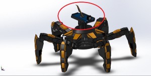
This semester, Spiderbot will try out a new method for the pan and tilt portion of the robot. The pan and tilt portion of Spiderbot was designed so that the placement of the smart phone with the Arxterra app will be flat and face-down. This can be seen in the SolidWorks design shown below:

Blog14_image1

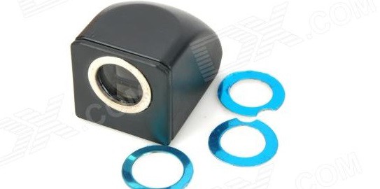
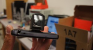
In this position, the smart phone will be unable to capture live video of the objects in front of it while in motion. To remedy this, an A8022 periscope will be attached by magnet to the smart phone camera.

This product can be found at this website for a fairly cheap price:

http://www.dx.com/p/a8022-creative-periscope-attachment-for-iphone-ipad-black-206277#.U2mRyvldUSM

 SONY DSC

This attachment maintains the original image quality of the smart phone and offers a good field of vision for the Arxterra Control Panel display. A video of this attachment in use can be found at the following link:

http://youtu.be/KZ8glROwRx4

Chop Suey: Chopped

By Matthew Clegg – Computer & Control Systems

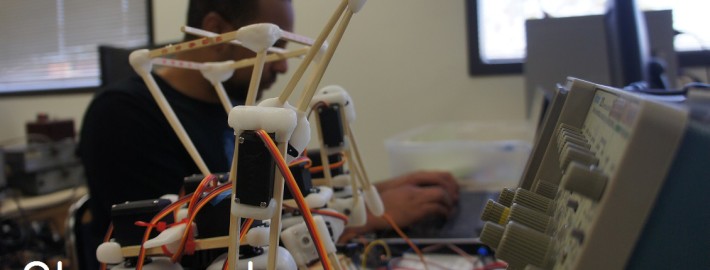
Many issues were faced when working with prototype Chop Suey. During the initial stages of coding, a single servo was connected to a single breakout board, with power being supplied by a DC power supply in a CSULB classroom. When code was uploaded, the servo would execute what it was instructed to do. This was the case when servos were connected for two legs of Spiderbot (6 servos, 3 servos per leg).

SONY DSC 

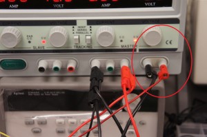
When more than two legs were connected to the breakout boards, Chop Suey seemed to have a mind of its own. Since the cause of the issue was not known, current was increased to its maximum for 6V on the power supply. The same issue occurred, so different inputs of the power supply were tried. The best results initially occurred when the leads for the breakout boards were connected to the fixed voltage and fixed current inputs for the power supply. After discussion with the creator of Chop Suey, David Gonsalez, it turned out that similar issues were faced in the previous semester because the DC power supplies do not provide enough current for sufficient control of all the servo motors used by Spiderbot.

SONY DSC

Though this input allowed for better control of the servos, it ultimately caused one of the breakout boards for Spiderbot to smoke and no longer function properly. In that situation, too much current was being provided to the boards.

SONY DSC

Luckily, Hexapod, Spring 2014 had extra breakout boards for purchase, so Spiderbot group is very grateful for that. The upside of this downfall, however, is that the reasoning for using breakout boards as a form of protection from damage for the Arduino and the servo motors has been verified, seeing as to how our Arduino Uno and all of our servo motors are still operating properly.

3D Mold Making

By Simon Abatay – 3D Molding & Manufacturing

Video By Kristine Abatay

After receiving the 3D-printed parts from manufacturing manager, Ali, it came time to create the mold for casting. The purpose of molding and casting the part is to eliminate the amount of time it would potentially take to print several pieces. The downfall is that the method can become costly if not done properly the first time. Molding and casting also allows projects to have replacement parts if any of the parts break or get damaged.

(Note: this method is only useful if you plan on mass producing a part or plan on having back up parts. If you only need 1 or 2 pieces, it is recommended to use the 3-D printer.)

This post explains the method of mold making that was used to make components for Spiderbot.

Materials:

  • Oomoo 30
  • Plastic tools to dispose of.
  • Oil Based Clay
  • Hot glue and glue gun
  • Polycarbonate sheets or lexan sheets
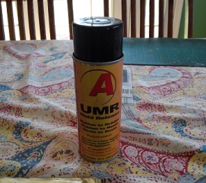
  • Mold release spray for silicone and rubber
  • Clear plastic cups for mixing
  • Aluminum foil

Process:

  1. Lay the aluminum foil down so you have can protect your work surface.
  2. Cut the plastic sheets to size. (This size is much larger than the piece you are trying to mold.)
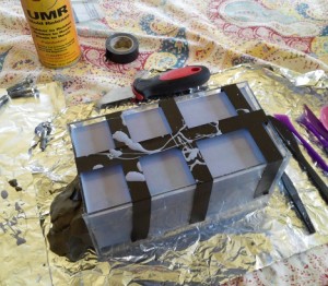
  3. Using the glue and glue gun, build a box out of the plastic sheets around the part.
  4. Using the oil based clay. Fill half of the box with the clay and submerge half of the piece in the clay.

Blog12_image1 

  1. Make positive keys in the clay. (These keys will help with aligning the mold when you are ready to cast.)
  2. Pour the 2 parts into two different cups while making sure they are of equal amounts as the instructions indicate to mix them at a 1:1 ratio.
  3. After making sure the mixture of the two parts is a uniform purple tint, pour it into the box submerging the exposed half of the part.
  4. Let cure for 6 hours.
  5. After curing, flip the box over and remove all clay.

10. Build a clay cylinder and place it on the highest point of the newly exposed part. This will be the spout for the plastic resin to pour into.

Blog12_image3 

11. Spray down the box and newly exposed part with the mold release spray. (This spray will prevent the just cured half of the mold from sticking to the new half.)

Blog12_image2 

12. Repeat steps 6 through 8.

13. After the final half of the mold is cured, remove the mold from the box.

Blog12_image4 

14. Pull the molds apart and remove the 3-D printed piece.

15. You may now begin casting your part!

This video was used as a reference to make molds and was provided originally by the supplier.

https://www.youtube.com/watch?v=FQ1A7ZjTsx8

This second video shows the process above being applied to the creation of a tibia piece for Spiderbot:

http://youtu.be/OL3B0jtyZZw

Spiderbot Systems and Interactions

By Matthew Clegg – Computer & Control Systems
and Kristine Abatay – Project Manager

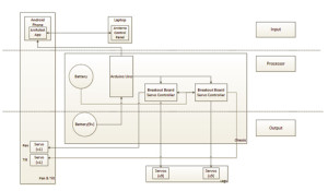
The following figure is a top-level systems diagram for the planned configuration of Spiderbot:

Blog11_image2

The method for powering Spiderbot from the Fall 2013 semester has been adapted at the moment, since the components used involved a NimH battery pack, as opposed to a LiPO battery, which would allow Spiderbot to meet the level 1 safety requirement.

This next figure was created by Matthew, using the program Fritzing, to show how the servos for Spiderbot will be connected to the microcontroller:

 Blog11_image3

As was stated in a previous blog, Spiderbot will execute code using an Arduino Uno R3, which does not support the amount of servos that will be used. This will involve the use of breakout boards, which are shown in the diagram above. Power will be supplied to the Arduino Uno and the two breakout boards separately. In addition to providing accommodation for all of the servo motors, the breakout boards serve as a sort of “protection barrier” between the servos and Uno, which is an added bonus, considering it would be cheaper to replace a breakout board than it would be to replace an Arduino Uno.

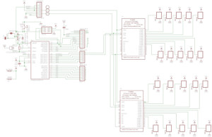
This final figure is a diagram, created by Matthew using the program Eagle CAD, displaying the connection of each individual operational component for Spiderbot:

Untitled-1

These connections are described in the following interface matrix.

Blog11_image4

This diagram shows the allocation of pins of operational components of Spiderbot. Overlap between the components demonstrates interactions that will allow the servo motors to communicate with the microcontroller.