Spring 2016: 3DoT David Gear Instability

BY: Andrew Saprid ( Manufacturing Engineer)

Introduction:

By assembling the gears into the bottom plate, making the connection was going to be an issue of stability and movement for the gears. The project manager and manufacturing engineer went to Lowes to buy screws for the connection. But turns out that the holes on the bottom plate did not print the exact measurement on Solid-works, making the holes too small or big.

Some tests were being made for the small motors and big motors by the electronics engineer and manufacturing engineer.

Requirements

Level 2 system requirement follows:

  • The 3DoT David shall use two micro motors for the movement system of the robot.

Testing #1

The project manager suggested that the screw would fit exactly on the gear, but make the hole a little bit bigger on the bottom plate, so that the gear would rotate on the bottom plate. The manufacturing engineer drilled the hole on the bottom plate, but broke some of the planks that were super glued into the bottom of the bottom plate. He cut off the screw to cut the weight of the screw, which may not make a difference for stability. He noticed the friction of the bottom plate may affect the movement of the gears.

cutted_screws  whiteboard
Gorilla tape was used to tape the planks to the bottom of the bottom plate. With using the small motor that the project manager bought in Amazon, they tested the motor to see if it will work, and it turns out that the friction, the screws, and the gorilla tape were causing problems with the motor turning the gears.
testwhiteboardsmall motor
Testing #2: White gears

Since red gears may be heavy for the small motors to run, white gears are placed on the wooden prototype for testing. They tested them with the small motor the project manager bought. They were running smoothly. The white gears were light. Driving a nail through the center of the hole of the gear will insure stability if the nail is driven to the wood straight downward. The small motor will run well with these gears, but the project manager wanted to use the red gears because they were stable and strong to withstand the weight of the legs. With legs and the joint attached to the white gears, the leg was putting weight into the gears, which caused instability of the gear train.

whitegearsboardleg_woodenboard

White Gear Testing With Motor VIdeo Link

Testing #3:Testboard, Oil, and Washers

In order to make the gears move freely on the bottom plate, washers and oil will be added. These were bought at Home depot.
washersoil

TestBoard

A test board was made in Solid-works to test the gear stability, movement, and friction. The original test board was not documented. The test board below has been tested, and the results of the testing have damaged the cylindrical extrusions by hammering a nail to it to make the gears stay in place as the motors drive the gear. By putting oil into the plate, and washer underneath the gear, the gear was able to move freely. The cylindrical extrusions did its job stabilizing the gear train. Finding a nail, screw, or etc to hold the gears in place is in progress.

originaltestplatetestboard

Conclusion

The electronics and manufacturing engineers did 3 tests for the white gears, red gears, and the extrusion of the bottom plate. The white gears are not going to be used because they are too light. The red gears will be used instead. They will be able to withstand the weight of the legs. Kent used the big motors. Big motors were able to move the red gears. Motors are still being investigated and researched by the electronics engineer for a small motor with more torque to the turn the gears better.Testing #3 could be the solution to the gear stability, friction, and movement. In order for the gears to move properly, perfection and accuracy is key.

Red Gear Testing With Motor Video Link


Spring 2016: 3DoT David Rapid Joint Connection (Between Gear and Leg)


BY: Andrew Saprid ( Manufacturing Engineer)

Introduction:

The joint implemented will be lightweight and easier for the motor to operate the legs of the 3Dot David as it completes its mission. In addition, it must be able to rotate the legs for free movement.

Related requirements

Level 2 system requirements follow:

  • The 3DoT David shall use two micro motors for the movement system of the robot.

Printing a joint in Solid-works

A joint is made in solidworks to be 3D printed. The problem with this design is the shape of the joint may interfere with where the screw, or nail is going to be placed at through the center hole of the gear. It would require a lot of sanding.

jointprinted

Tube from a mechanical pencil as a joint

Another solution was to use a tube that holds the leads inside of the mechanical pencil as a joint. The tube had to be sanded in order for it to fit inside the hole of the gears. However, the tube gets stuck on the gear, so the tube does not rotate on the gear. A lot of labor would be put into for sanding those six tubes as the joints.

mechanical_pencil

A Joint in one of the white gear bag

We found a joint solution in one of the parts in the white gear bag. This joint has a length of about .939 centimeters. It’s diameter on the bottom of the joint is about .487 centimeters. The diameter of the hole on the bottom is about .196 centimeters, which the screw will go into the hole.
whitegearsScreen Shot 2016-04-25 at 7.28.21 PM

We went to Jk electronics to buy screws and washers to create the joint. The screws cost $2.49, and the washers cost $3.75. The hole of the diameter is about .287 centimeters. The diameter of the screw is about 0.2 centimeters. The length of the screw is 0.753 centimeters.
screw_joint_washerThe joint is then assembled together. The washer with the screw is placed on the bottom side of the gear. That way the joint does not come out of the gear as the joint rotates in a 360 degree motion. This would not require any hard labor of sanding to fit it into the gears, saving a lot of time.
joint-gear   screw_gear

Conclusion

The part in the white gear bag will be used as a joint as it was able to rotate on the red gear.


Spring 2016: 3DoT David Servos and Motor Trade-off Study

BY: Kent Hayes (Electronics and Control)

Introduction

A servo is an assembly of 4 different things: a DC motor, a gear-reduction unit, a position sensing unit, and negative feedback to control the motor’s speed/position. Unlike the DC motor, servos use a 3 wire connection for the power, ground, and control. The servo receives a control signal (PWM) that represents a desired position and powers the motor until its shaft reaches this desired position. They are typically able to rotate 200 degrees back and forth.

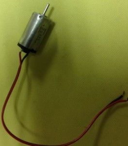
A DC motor uses only 2 wires, through which all of the power is supplied. The power level is controlled by PWM which is a ratio of the on time and the off time or the duty cycle. So if the power is on for half the time, then the motor operates with half of the power of its full-on operation. However there are various types of motors, so in the resources section you will see a link which has nice summaries of the different motors and which ones will be of the best use to the reader.

Types of Servos:

  • RC Servos. The most common and economical type of servo motor that normally come with 180 degree range for rotation. You can drive these through servo controllers or through GPIO pins from a microcontroller. A major disadvantage of these is that there is no feed back to the program of which you use to control them, so one cannot be entirely sure that it is operating properly.
  • Analog Feedback Servos. Come with an extra feedback wire that you can connect to an analog input pin in order to get feedback to the user’s program.
  • Continuous Rotation Servo. They are “hacked” RC servos, meaning that the controller feedback is hard-wired to believe that it is always at a middle position, resulting in a reversible, speed controlled gear-motor. A disadvantage is that it can be difficult to find the neutral point in the control signal where the motor stops using all together.

Types of Motors:

  • Brushed Motors. The most common type of motor because they are light, inexpensive, efficient, and have reasonable torque at low speeds. Can be used in toys, RC servos, and even gear motors.  
    • A gear-motor is a brushed motor with reduced speed but increased torque through the use of a gear-train.  The reduction of speed is actually an advantage because most DC motors spin too fast. A disadvantage is with the extra resistance, the gear-trains will become unresponsive at lower voltages.
  • Brushless Motors. Replaces the brushes with electronic communication to switch the current flow to drive the motor, while maintaining its efficiency. Typically used in laptops as fans and quadcopters. The main disadvantage is that it normally requires a separate controller for operation.
  • Stepper Motors. DC motors that move is discrete steps so they have much more precise speed control. Another advantage includes having a reasonable low-speed torque. The main disadvantages include reduced efficiency and being subject to missing steps if overloaded.

Servo Trade-off Study Guiding Factors

The purpose of the servo was to control the rotation of the head, while the motors would control the movement of the legs. In choosing a servo, we would need it to rotate 360 degrees continuously within our voltage range of 3.7V to 5V. In addition, it should be lightweight, small in size, and inexpensive so that it not bring us over our budget. The following table are the results from what Kent was able to find online:

Motor Trade-off Study Guiding Factors

After reading about the different types of motors, I  began to look at motors that would work for the 3DoT David team. The main factors that contributed to his search were the following: size, cost, and voltage rating. The size is important to our project since the mechanical design has been shrunk in size compared to previous generations of spider bots. Our budget for the project is not supposed to exceed $80.00 so it is best to be aware of how much each type of motor will cost. Finally, it is important to have a motor that can operate within 3.7V~ 5V since the 3DoT board will allow us to operate within this range. After searching online, the only motors that were able to fit our specifications were of the brushed motor type. All other stepper motors and brushless motors were either too large or had too high of a voltage rating. In addition, they both require separate controllers and are much more complicated to control.

Update:

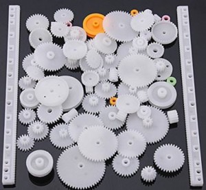
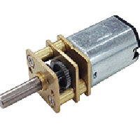
After our team team received new gears, we began testing to see if the motors would still be able to work. Unfortunately, they did not have enough torque to turn our gear train. Kent then began to test with the DC hobby motor, which did have enough torque but was too heavy and bulky to work with our design. He then turned to the E&C division manager for possible solutions and he recommended that we take a second look into geared motors.

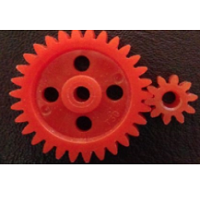
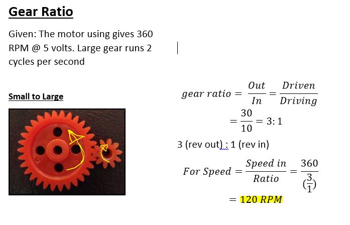
After looking online, Kent found a list of micro geared motors from the Servo City website. They had various motors from 45RPM to 2500RPM and as the speed increased the torque decreased. Therefore when searching, we had to make sure we had enough torque at a speed that would make our legs rotate at a reasonable rate. We agreed that 2 cycles/sec would be an appropriate speed to enable the spider to walk. In order to acheive this, hr did the following calculations:

2 cycles/sec * 60 sec/min = 120 cycles/min (RPM)

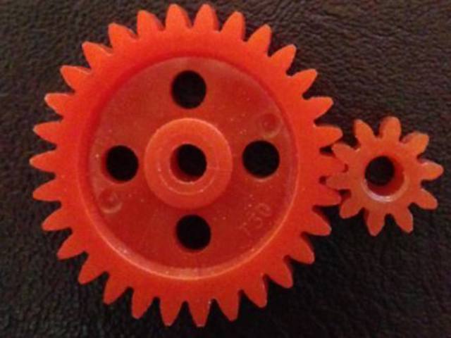
The gear ratio we are using is 3:1 so,

120 RPM * 3 = 360 RPM

So 360 RPM is the minimum speed we need motor to rotate in order for the micro geared motor to rotate our legs at 2 cycles/sec. Therefore we purchased 2 micro geared motor that have 450 RPM at 6V. We will not reach 6V due to our board only being able to supply 5V, so as the PWM signal gets closer to 5V we should be able to reach 360 RPM if not greater. Once they arrive, we can begin to test to see how reliable they are and if we will need to choose something else.

Trade-off Studies Tables

Servo-Trade Off Study

Requirements Met Servo Name Price

Torque

(kg)

Speed

Voltage (V)

Weight

(g)

Dimensions
-Supply voltage is realizable since we can do anything between 3.7 and 5V. Single Cell 3.2g / .16kg / .10sec Digital Ultra-Micro Servo $7.95 .16 ~.19 .1s~.08 sec/60 degrees 3 ~ 4.2 3.2 28mm x 9 mm x 22mm
-Supply voltage is realizable since we can do anything between 3.7 and 5V.

-Weighs less than 2 g

Ultra Micro Servo 1.7g for 3D Flight $4.34 0.08 0.12 sec/60 degrees 3.7 ~ 4.2 1.7 12 mm x 21 mm x 0mm
-Supply voltage is realizable since we can do anything between 3.7 and 5V.

– Affordable since it is less than $4.00

-Weighs less than 2 g

HK-5330 Ultra-Micro Digital Servo 0.17kg / 0.04sec / 1.9g $3.64 .12 ~.17 .06~.04 sec/60 degrees 2.8 ~ 4.2 1.9 20 mm x 6 mm x 23 mm
-Supply voltage is realizable since we can do anything between 3.7 and 5V.

-Affordable since it is $3.99  

-Weighs about 2 g

HK-282A Single-Screw, Ultra-Micro Servo 2g / 0.2kg / 0.08sec $3.99 0.2 0.08 sec/60 degrees 3~4.8 2 23mm x 8mm x 20mm
-Can rotate 360 degrees Continuous Rotation Micro Servo FS90R $7.50 1.3~1.5 110~130 rpm 4.8~6 10 32mm x 12mm x 30
-Can rotate 360 degrees Continuous Rotation Servo – FeeTech FS5103R $11.95 3~3.2 .18sec/60 degrees 4.8~6 40 37mm x 20mm x 54mm

Motor Trade-Off Study

Name Requirements Met Rated Volt Max Volt Min Volt No load Current Stall Current No Load RPM Power Rating Weight Size Price
DC Toy/ Hobby Motor Cost effective 6V 9V 2V 70mA 500mA 7300~10900 420 mW 17.5 g 27.5mm x 20mm x 15mm $1.95
Hobby Motor -Cost effective 3V 12V 1V 110mA N/A 6000~7200 330mW 26g 2.75cm x 2.75 cm $1.95
3.7V 50,000 RPM Small Colorless Motor 716 -Operational voltage is reachable.

-Cost Effective

-7mm diameter

3.7V N/A N/A 100mA 1.35A 50000 5W 2.5g 16.5 mm x 7mm $1.95
FA-GM6-3V-25 Micro Motor Mini Motor -6mm diameter 3V N/A N/A 100mA N/A 1200 300mW 1.2g 20 mm x 6mm $9.00


Conclusion

  • Servos are excellent in terms of precision of control which is why we first considered using them for our robot.
  • In addition, they have a great amount of torque for dealing with heavier loads.
  • However, after looking into greater detail, we realized they might not be as useful to our project as we previously thought.
    • They are much too bulky to fit inside the spider.
    • Their price is quite unreasonable when being compared to the motors.
    • Would only be able to get the CR servos(for the 360 degree rotation of the head)


  • The 3.7V 50,000 RPM Small Colorless Motor 716 has more advantages for our application when compared to the rest of the available options.6
    • Its rated voltage is realizable since our battery is going to be 3.7V,
    • Max(stall) current is 1.5A which is excellent since our motor driver will might output 1A maximum
    • It is only 2.5 grams
    • Reasonably priced, $1.95
  • Only disadvantage of this motor is that we do not know the torque specifications and will have to do my own calculations based on the information given. These calculations will be placed in a separate blog post  if you wish to see them.
  • Project Update
    • The mechanical design of our 3DoT david changed in order to make the assembly much simpler than before, and will therefore not require us to use servos. The new design has it set where one motor will control the right side of the legs and the other will control the left side.

GearedMotor_Pic_BlogPost

Resources:

https://learn.adafruit.com/adafruit-motor-selection-guide/types-of-motors

https://www.adafruit.com/products/711

https://www.sparkfun.com/products/11696

http://www.seeedstudio.com/depot/37V-50000RPM-Small-Coreless-Motor-716-p-1884.html

https://www.firgelliauto.com/products/mini-motor-micro-motor

https://www.servocity.com/html/micro_gearmotorblocks.html

http://www.hobbyking.com/hobbyking/store/index.asp

http://handyboard.com/hb/faq/hardware-faqs/dc-vs-servo/

https://learn.adafruit.com/adafruit-motor-selection-guide/continuous-rotation-servos

https://learn.adafruit.com/adafruit-motor-selection-guide/rc-servo-control
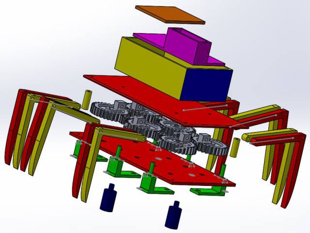
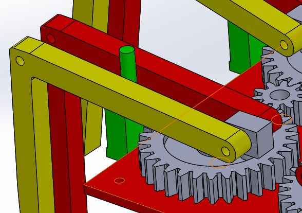
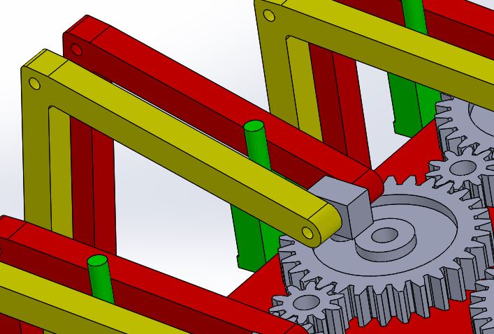
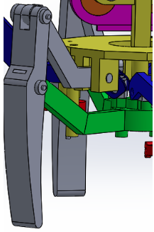
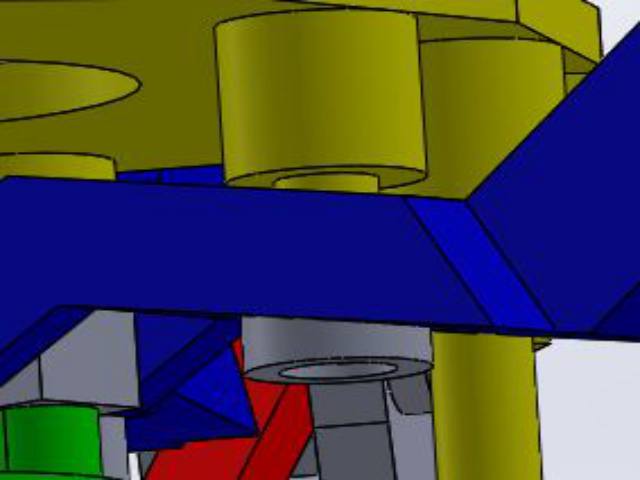
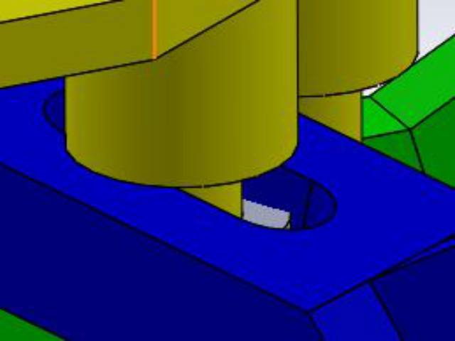
 

Spring 2016: 3DoT David Board Troubleshooting

BY: Christopher Hirunthanakorn (Missions, Systems and Test Engineer)

Introduction:

After receiving the assembled 3DoT board that my project manager (Omar) and manufacturing engineer (Andrew) put together, tests were performed to make sure the board was functional. The basic firmware was uploaded by the assembly team, so that step was skipped. More information for uploading firmware to the 3DoT board can be found in Tae’s post for the 3DoT Goliath.

Related Requirements:

  • The 3DoT David shall be a robot that demonstrates the capability of the new 3DoT micro-controller for DIY hobbyists.\

3DoT David Board Troubleshooting

There were four tests to check the functionality of the 3DoT board, which are listed below.

  1. 3DoT board can be turned on and off by using the switch.
  2. Arxterra App can connect to the 3DoT board via bluetooth.
  3. Two motors can be controlled by the 3DoT board.
  4. The battery can be recharged when a micro usb cable is connected as indicated by the LED.

After performing all of the tests, it was found that there was an issue with the motors. When a motor was connected to the motor A connection, it would operate normally. However, that same motor would not work for the motor B connection even though the code was driving both motor connections at the same speed.. It should be noted that this issue was also found on the 3DoT board that the 3DoT Goliath assembled.

image

In order to address this issue, Tae, Nick, and I met up to troubleshoot the problem. The following code in order to test both motor connections at the same time.
code

The following test procedure was used to find the source of the problem.

Test Procedure:

  1. Take out the battery before testing using a multimeter
  2. Set the multimeter to measure resistance setting in the 100k ohm range
    1. Check for shorts on the TB6612FNG Dual Motor Driver Chip
    2. The measured impedance of any two pins should be much higher than the 100k ohm.
    3. If a value of 0 resistance or close is displayed, then there is a short.
  3. Plug the battery back in and turn on the 3DoT board.
  4. Measure the voltage across the motor terminals to make sure the correct voltages are outputted.
  5. Measure the voltage across the Atmega 32u4 pins that are connected to the TB6612FNG Dual Motor Driver Chip to make sure the correct voltages are outputted. Those pins are PB5, PB6, PC6, PD7, PF5, PF6, and PF7.
  6. Record results

The results of our test are as follows:

  1. There were no shorts on the TB6612FNG Dual Motor Driver Chip.
  2. We measured the expected 5 Volts at the motor A connection but no voltage was detected at the motor B connection.
  3. We measured 3.3 Volts for the motor A connections from the Atmega 32u4 pins but we measured 2.67 Volts for the motor B connections. We were unable to find out what was causing the motor B connections to have a different voltage than the expected 3.3 Volts.

Nick tried unsoldering and resoldering the dual motor driver chip but that had no effect on this problem. He told us that the possible causes of this issue could have been from the shipment of the parts, electrostatic discharge, heat, during assembly, etc. Because no solution was found, we informed Professor Hill about this issue and returned the 3DoT boards to be analyzed and repaired. We are currently using a Sparkfun Pro Micro as a replacement for demonstrations and testing.

Conclusion:

This experience showed the importance of testing all components that are purchased or received to make sure they are functioning properly. It also highlighted the importance of troubleshooting and establishing a procedure for testing and recording results.

Update: The 3DoT Board has been fixed and is fully functional.

Sources:

  1. Spring 2016: 3DoT Firmware upload to 3DoT Board

Spring 2016: 3DoT David Simulation and New Design Parts

BY: Andrew Saprid ( Manufacturing Engineer)

Introduction:

Since the first prototype made in solidworks was difficult to 3D print, the parts had to be redesigned. They have to be as flat as possible to make it easier for the 3D print the parts.

Related requirements:

Level 2 system requirement follows:

  • The 3DoT Spider shall incorporate 3D printed parts for the legs, body, or head. This follows from the level 1 requirement dictating the limit on 3D printing times.

Table of Contents

3DoT David Model exploded view and simulation

Exploded View

David_exploded_view1Simulation

A simulation is shown to clearly define the movement system in different views: 

Full view NewdesignFullview Corner viewNewDesignSideView

Top viewNewDesignTopView

New Design Parts

Chassis

The new design is made in solidworks.These are the top and bottom plates. The top and bottom plate will be assembled together as a chassis for 3Dot David Spider. The dimensions for these plates are 12 centimeters in length and 7 centimeters in width with an extrusion of 0.2 centimeters for each plate. For the bottom plate, holes are 0.39 centimeters. They are made to fit the gears as they rotate on the surface of the plate. Small holes, dimensioned at 0.2 centimeters in diameter,  on each plate connect them together. For the top plate, 0.2 centimeters holes are made in the middle to connect the PCB box on top of the plate.

Chasis

Gears

Gears are bought in Amazon.The large gear has 30 teeth, and measures to be 3 cm. The small gear has 10 teeth, and measures to be 1 cm. 6 large gears and 4 small gears will be used to make the gear train. Calculations are done to obtain the gear ratio.

Refer to Gear train blog post for details (Spring 2016: 3DoT David Gear Train)

GearsLegs

Femur and the tibia are combined as one leg part. The length of the femur is 4.78 centimeters. The length of the tibia is 5.3 centimeters. The hole on the femur is 0.25 centimeters in diameter. The hole will connect the joint as shown on the right. Two legs will have the same dimensions as it connects to joint. The space between the two legs will have 0.5 centimeter cushion.

Leg_study1     gearmotion2

Joint

The joint measures to be 0.8 centimeters in length and 0.6 centimeters in width with an extrusion of 0.5 centimeters. The hole in the box is 0.20 centimeters. The cylinder connected to the box is 0.29 centimeters in length with a diameter of 0.39 centimeters.

Screen Shot 2016-04-11 at 12.06.02 PM

Plank, Solidworks modeled gear, and leg studies

This part is called the plank that will be attached to the bottom of the bottom plate. The reason for the plank is to make the leg, connected to the gear,  lift up in an angle as the gear rotates in a full 360 degree rotation. In the 3 centimeter gear, the radius 0.76 centimeters. The gear is modeled to simulate the gear train in Solidworks.

Refer to leg study blog post for calculations ( Spring 2016: 3DoT David Leg Movement Angle Study)

Plank       Screen Shot 2016-04-11 at 12.08.41 PM


In the middle gear of the gear train, the leg is lifted because of the plank. The lift is about 13.30 degrees according to the leg study. This is the position that it will start for the middle gear.

gearmotion

The position that the corner gear of the gear train will start at is 5 degrees as the leg rests on top of the plank, where the cylinder stops the leg from going anywhere else.

gearmotion2


Gear view

A better view is shown from the top as it shows the gear train and the position of all the legs. 12 legs will be used, and 2 legs will act as one part with the same dimensions.


Gear_view

Conclusion:

The previous design was difficult and complex to build similar to the Hexbug Spider. The new design is made to simplify the CAM Movement system of the HexBug Spider, which will be applied to the legs connected to the gears, as the two motors (located on the bottom plate) will rotate both sides of the gears in a full 360 degree rotation. The two motors will attach to the 1 cm small gears.


Spring 2016: 3DoT Spider-Bot Mechanism Research

BY: Omar Mouline ( Project Manager)

Introduction

The 3Dot David project mechanical requirement was to build a small size spider bot that can walk using two motors. When the project was assigned to us, We were given The hex bug 1 in the picture below  as a prototype. Screen Shot 2016-04-09 at 2.15.27 PM

Related requirements

  1. The 3DoT David shall be a low cost project with a total cost that does not exceed $79.95, which includes the cost for manufacturing, PCB, battery, and other components.

Table of Contents

Research different mechanisms of spider bots

After conducting some research on other types of mechanisms, the first design that attracted my attention was a toy named  “Combat Creature”. The Combat Creature is a discontinued toy that i believed was cooler that the hex bug to build.

Combat creature

Screen Shot 2016-04-09 at 3.25.07 PM 
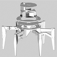
A 3 part video Youtube video of disassembling the toy was found explaining the mechanism and showing the different parts of the robot: Part 1Part 2, and Part 3.

Jerry Mantzel mechanism

Screen Shot 2016-04-09 at 3.29.37 PM

Jerry Mantzel project was to build a Giant Version  of the Combat Creature. Inspired by the combat creature, he adjusted the design of the toy to make a Rapid Prototype as shown in Video.  Adjustments were made To have an easy prototype to 3D print as shown in this  Video.

Hex Bug 1 Mechanism

Screen Shot 2016-04-09 at 3.57.35 PM

This prototype is the design that was assigned for our project. The picture on top show the exploded view of the cam based mechanism of the spider bot.

Hex Bug 2 Mechanism

11oych Gear_view Side_view-1

This design is the new design we are using for our project. It is less complex, gave us less printing time, All the parts can be 3d printed, and reduce the cost of manufacturing.

Joe Clan Mechanism

steamspiderOn this design the Spider Bot move side ways. I found a lot of information in this Page. The Professor provided me with more links for this model:

Two motors controlled transparent Joe Clan

Leg Movement Mechanism

Phone Controlled based Mechanical Joe Clan Spider

Legs movement

Theo Jansen Mechanism

Strandbeest--Full-Walking-AnimationStrandbeest-Walking-Animation

Links That explain more the mechanism of this Spider Bot:

Details on Theo Jansen mechanism

Adam Savage’s One Day Builds

A Theo Jansen´s mechanism

Theo Jansen style robot leg

Walking machine in the middle of construction

Baling Wire Walker

Conclusion

After looking on all of these design, we started working on the Hex Bug mechanism 1 and on process of designing it on solid works we quickly started running to problems. Trying to solve all the problems the main issue we had is the 3D printing quality for the small joints and some other parts. for that small design we needed precision in order to get the result we want specially for an important part like the joint. We then decided in the tenth week as a team too change the design to the Hex bug mechanism 2 which is less complex. Gladly, we were able to make and achieve all the requirements.


Spring 2016: 3DoT David Printing Time

BY: Andrew Saprid ( Manufacturing Engineer)

Introduction:

Calculations were done by adding the quantity to the table and adding the total amount of printing time for each part. The calculations for all the parts are then added and highlighted on each of the three tables for the total print time of all the parts.

Related requirements:

  • As part of our level 2 requirements, 3D printing time shall not exceed the 6 hour limit. Each part will not exceed the 2 hour limit of printing. Three tables are shown in the figure below to compare scenarios, if all the parts are to be 3D printed.

All parts printed

If the parts are all printed, it takes 7.78 hours, which exceeds the 6 hour limit of printing.

12 legs to be printed takes 132 minutes to print. Each leg to print takes 11 minutes.

4 connectors takes 8 minutes. Each connector to print takes 2 minutes.

6 joints to be printed takes 6 minutes. Each joint to print is 2 minutes.

6 planks to be printed takes 8 minutes

Each part did not exceed the 2 hour limit print time.

exceedlimitBottom plate and Top plate excluded

By excluding the top and bottom plates to be laser cutted, it takes about 4.49 hours, which goes below the 6 hour limit of printing.
hr4.49Excluding the PCB box and cover

By excluding the PCB box and PCB box cover, it takes about 5.5 hours, which also goes below the 6 hour limit of printing. The PCB Box and the cover makes the PCB invisible to the eye, which does not affect the level 1 requirements, and saves printing time.

hr5.5Conclusion
The best results are excluding the top and bottom plate to be laser cutted, or excluding the PCB box and PCB box cover. The best scenario would be to exclude the PCB box a
nd cover. The rest of the parts will be 3D printed, which takes about 5.5 hours.

Sources:

Thanks to Min, the manufacturing engineer from the Velociraptor Team for printing all the parts, the results are in for the 3D printing time.

Spring 2016: 3DoT Spider-Bot Cam Simulation

BY: Andrew Saprid ( manufacturing engineer)

Introduction

The initial design assumed that the CAM movement system would be used. Therefore, research on the CAM system and this CAM simulation were performed.

Requirements

Level 2 system requirement states:

  • The 3DoT David shall use two micro motors for the movement system of the robot.

Table of Contents

CAM movement system model

All parts are assembled and connected with the top base and bottom base. The difficulties of making the CAM simulation included many mating in assembly that crashed the solidworks software many times. To prevent the solidworks software from crashing, mates may have to be suppressed so that resources may not be used as much in the software. A lot of parts will be 3d printed, and may exceed the 6 hour limit.

fullview

Here is the CAM and follower simulation of the 3Dot David model. By moving the CAM connected to the follower, three legs will move up, while the other three legs will move down:

CAM

Looking closely to simulate of the CAM movements system of the Hexbug Spider, steps are broken down to analyze and observe each part. The follower (yellow) is connected to the CAM (orange). By moving the follower, it will rotate just as the CAM rotates. The top femur (blue) is connected to the bottom femur (green).  It’s support (red) will be connected to the bottom base. The bottom femur support (gray) will be connected to the top base.

CAM_SimulationBLog
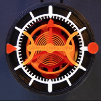
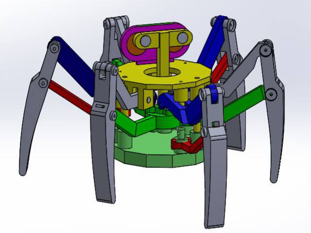
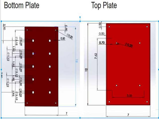
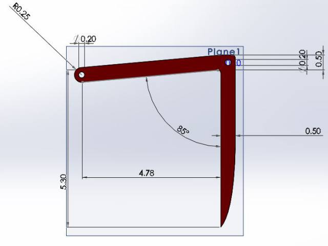
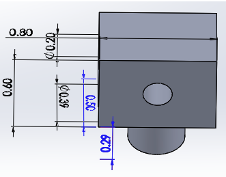
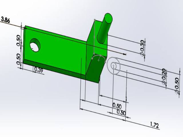
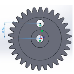
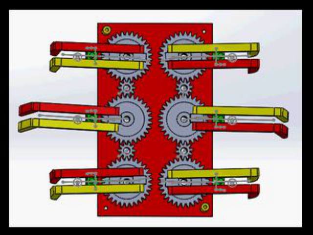
Hex bug design parts
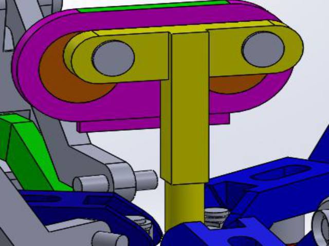
Follower, CAM, and CAM cover

The follower (yellow) is connected to the CAM (orange). The CAM cover (purple) holds the CAM and follower in place.

CAM_Follower

Top femur

Top femur (blue) is connected to the joint(gray).

topview

Joint

Joint (gray) is then connected to the bottom femur (green). This will make the joint free to rotate, and the top femur (blue) to go up and down.

joint

Tibia

The tibias (gray) are then connected to the femurs.CAM_SimulationBLog1

Bottom Femur Support and Top Base

The bottom femur support (gray) is the connected to the top base (yellow).

Screen Shot 2016-04-11 at 10.36.29 AM

Bottom Femur Support and Top Base

The bottom femur support (gray) is the connected to the top base (yellow).

Screen Shot 2016-04-11 at 10.38.03 AM

Slot bolt and the slot hole on the top femur

The slot bolt (gray) will restrict the top femur (blue) from going out. When moving the follower, the top femur will move, dependent on the slot hole.

slotconnection slothole

Conclusion: CAM movement system model

All parts are assembled and connected with the top base and bottom base. The difficulties of making the CAM simulation, it included many mating in assembly that crashed the solidworks software many times. To prevent the solidworks software from crashing, mates may have to be suppressed so that resources may not be used as much in the software. A lot of parts will be 3d printed, and may exceed the 6 hour limit.

Spring 2016: 3DoT David Gear Train

BY: Andrew Saprid ( manufacturing engineer)

Introduction:

The mechanical system for the 3Dot David is the gear train. Gears have teeth, which are designed to make the gear train rotate 360 degrees possible. The motor will operate around 5 volts, and it will be connected to the small gear as it drives the large gear. With the gear train setup, the 3Dot David will be able to move across the lyceum floor.

Related requirements

Level 2 system requirement follows:

  • The 3DoT David shall use two micro motors for the movement system of the robot.


Motor calculations:

The motor previously used at 50,000 RPM was not the right value because it was unrealistic for the spider to run at that pace, which could easily break components inside of it. In order for the legs to move at a slow steady pace, the motor using will give 360 RPM at 5 volts as the legs will run at a pace of 2 cycles per second.

The team will use the motor at 360 RPM to drive the small to large gears.
120 RPM / 60 sec = 2 cycles per second for the large gear The gear train is 120 RPM


gear_ratio_updated3

Conclusion

The team will use the motor at 360 RPM to drive the small to large gears.

120 RPM / 60 sec = 2 cycles per second for the large gear

Source:

http://www.engr.ncsu.edu/mes/media/pdf/gears

Spring 2016: 3DoT David Leg Movement Angle Study

BY: Andrew Saprid ( manufacturing engineer)

Introduction:

The leg must be lifted in order for the spider to walk. Supplying 5 volts will be efficient enough to lift the leg, and rotating 360 degrees continuously.

Related Requirements:

Level 2 system requirement states:

The 3DoT David shall use two micro motors for the movement system of the robot.

Leg Study

Calculations are done to find out the angle and the leg lifted off the ground. The calculated  circumference of the 3 cm gear came up to be 4.78 cm. The initial lift of the leg is to be 5 degrees. by using sine to find x, it came to be .42 cm. The final lift is 13.3 degrees. The same method is done which came to be 1.1cm. Subtracting .42cm to 1.1cm, came up to be 0.68 cm off the ground.


           Initial lift: 5 degrees                                                            Final Lift: 13.30 degrees

Screen Shot 2016-04-10 at 3.30.39 PMScreen Shot 2016-04-10 at 3.31.50 PM


The calculations are as follow:

Circumference of the 3 cm gear

C = 2πr  = 2π(0.76) = 4.78 cm

Given 5 degrees for the initial lift

sin(5) = x/4.78

4.78 x sin(5) = .42 cm  

Final lift is 13.30 deg

4.78 x sin(13.30) = 1.1cm

1.1cm – .42cm

= 0.68 cm off the ground