Spring 2017 SpiderBot : Firmware Blog Post

By Shaun Pasoz – Electronics & Control Engineer

Introduction

While waiting for the breakout boards to come in the mail, to make the best use of time the E&C division manager tasked us with coding quizzes. One of the quiz questions involved controlling the TB6612FNG motor driver using a microcontroller such as the Arduino UNO. Below is the snippet of code submitted for that quiz question along with the comments:

In order to allow easy calling of the functions for the MST engineer the moveIt() function was itemized into corresponding functions as follows: a forward move, backward move, left turn, and right turn. An example of the forward() function is demonstrated below:

This code displayed above allows for control of two motors by utilizing four digital pins and two PWM pins from the microcontroller all from the same function. From here the next step was to include the code to control the third motor that will be controlling the winch.

Since the 3DoT only has pins available for two motors, it was necessary that the third motor be controlled via I2C. After doing some research it became evident that the Adafruit Motor Shield V2 used the same primary ICs as our PCB. To avoid writing code to manually control the I2C protocol the Adafruit Motor Shield library was used. The following snippets of code demonstrates our implementation of the Adafruit Motor Shield library:

Conclusion

To summarize, the motor shield object is instantiated using the Adafruit library with an address of 0x60. Motor 1 is then instantiated (since our project only needed one motor to be controlled only one instance of the object is instantiated), where the logic pins AIN1, AIN2 and PWMA from the TB6612FNG IC is connected to PWM pins 0, 1, and 2 on the PCA9685 chip. In order to allow for this the Adafruit library .cpp file was changed such that AFMS.getMotor(1) corresponds to PWM pins 0, 1, and 2.

The object is then began in the setup function and STBY pin on the TB6612FNG IC is brought HIGH by setting PWM pin 15 to a 100% duty cycle. Furthermore, the winch motor is set to full speed since the system utilizes 3.3V to power the motor, full speed is adequate for all instances of the winch motor control. Lastly, the equivalent move function of the winch motor is itemized in a function, called goUp(), to easily be called by the MST engineer when programming Bluetooth communication.

Spring 2017 SpiderBot : Prototyping Blog Post

By Shaun Pasoz – Electronics & Control Engineer

Introduction

Before sending out the PCB design for production, it is necessary to prototype the design using breakout boards and through-hole components. This is a necessary step to test the components in combination with the code and make sure the design works. The purpose of our PCB is to allow control of a third DC motor using the 3DoT. Our design utilizes two IC’s: the TB6612FNG manufactured by Toshiba, and the PCA9685 from NXP Semiconductors.

The TB6612FNG is a dual H-bridge motor driver. It will be used in our PCB design to control the third DC motor. The pins utilized on the motor driver will be VM, VCC, AIN1, AIN2, PWMA, STBY, AOUT1, and AOUT2. The PCA9685 is an I2C compatible 12-bit PWM driver. Since the 3DoT provides no PWM enabled digital pins, the component is necessary in the PCB design to provide PWM to the motor driver. The extraneous PWM pins will be used as a digital signal to control the motor driver.

Seen below is a Fritzing diagram of our design alongside a picture of the actual implementation:

Figure 1: Breakout Board Fritzing Diagram


Figure 2: Image of Implementation of Breakout Boards

In an effort to avoid soldering and de-soldering leads to the breakout boards, the implementation is not as clean. The implementation also shows that the design can easily be powered from a separate power supply; in this case, a 9V battery.

Update:

Although the design works using breakout boards. When implemented on a PCB, the PCB did not work. This could be due to a couple reasons. One, it’s possible the IC’s got damaged in making the PCB as it was not built in an ESD safe lab. Two, it’s possible that there was a manufacturing error such as traces being placed too closely together, or traces poor insulation of the traces. The second choice is the suspected problem as we tried making three different boards, using new IC’s and testing both ceramic and tantalum capacitors.


Spring 2017 – SpiderBot Project Summary

Table of Contents

Project Overview

Executive Summary

By Nicholas Jacobs – PM

The purpose of SpiderBot is to make an inexpensive, fun toy that can walk, turn, launch a grappling hook, and raise/lower itself to/from a predetermined height. While anchored, SpiderBot will provide a live video feed to the Arxterra Control Panel.

System Design

By Jefferson Fuentes – MST

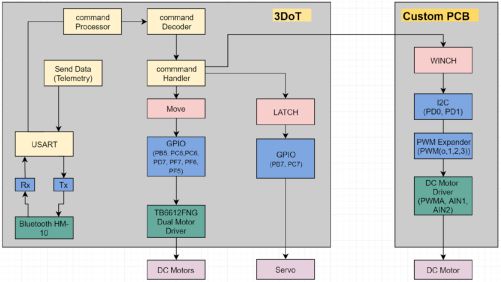
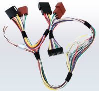
SpiderBot consists of the 3DOT controller board based around Atmel’s 32U4. 3DOT also incorporates the TB6612F Dual Motor driver that drive two DC motors that enable SpiderBot to walk. SpiderBot also has a custom built grappling  hook that is launched under rubber-band tension. Once the grappling hook anchors to a fixed position the custom made winch motor assembly hoists SpiderBot to an elevated position. The 3DOT board can only drive the motors meant for walking, the custom PCB incorporates another TB6612F to drive the winch motor, and a PCA9685 PWM Expander that enables the custom PCB to communicate with the 3DOT board via I2C. To see our System Block Diagram go here.

Subsystem Design

Experimental Results

By Nicholas Jacobs – PM

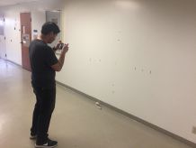
At the onset of our design,  multiple trade off studies to determine what parts are required to complete our requirements. Our material trade-off study explored SpiderBot’s possible composition, while the motor trade-off study  looked at possible DC motors that could best meet the customer requirements. Once the proper DC motors was picked and ordered, we conducted a motor torque test to verify that the chosen motors were up to the task. We also conducted an experiment that determined the most effective way to suppress DC motor noise generated by the commutators switching polarities.   Lastly, since SpiderBot’s purpose was to provide a live video feed to the Arxterra Control Panel from an elevated position, we had to determine what reliable size maze could be covered with the phone being used. The experimental steps can be found here.

Interface Definition

By Jefferson Fuentes -MST

Interface definitions are used to determine the connections within the project.  The most crucial component, the ATmega32u, is the the brains of the project and process all commands.  Interface definitions for the the custom PCB are also included, showing how to connect it all to allow for proper function.The final, most updated description that explains the the inner workings and connections for the 3DOT controller, and the custom PCB  can be found here.

Mission Command and Control

By Jefferson Fuentes -MST

One requirement stated that SpiderBot is to be controlled by the Axterra App via a bluetooth connection. The Missions System and test Engineer’s job was to configure any custom command and telemetry decoding and encoding schemes that were necessary for SpideBot’s mission. Instructions, software block diagram, Arduino code, and  a detailed description the Arxterra Control Panel set-up can be found  here.

Electronics Design

By Shaun Pasoz – E&C

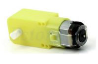
The motors that drive SpiderBot’s legs were initially GM3 DC motors. However the way they were mounted and the weight they had posed problems. Instead we settled on SparkFun’s MicroGear motors for they’re size, weight, low stall current, and very high torque output.  Pololu’s Microgear Motors.

Another capability that SpiderBot had was to launch our a grappling hook remotely via the Arxterra App. This was done by controlling a 3.3 volt servo from the 3Dot board. Since the grappling system is rubber-band actuated the servo unlatches a sear-style catch that allows the grappling hook to launch. Additional information can be found here click on 3.3volt_servo.

Firmware

By Shaun Pasoz – E&C

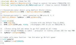
Firmware for controlling the 3DOT, custom PCB, and 3 DC motors, along can be found here.

PCB Schematic

By Shaun Pazos – E&C

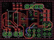
Our custom PCB incorporated an additional TB6612F motor driver to drive our winch motor that allowed for SpiderBot to climb. Also on our custom PCB is a PCA9685 PWM Expander and its main purpose was to relay data packets from the 3DOT controller to our custom PCB via I2C. Additional information can be found here click on Custom_PCB_Chips.

PCB Layout

By Daniel Matias – MFG

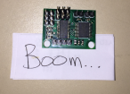
More information can be found on our Custom PCB blog post after it had been built and tested. Unfortunately, only briefly did the custom PCB work. It will forever remain a mystery as to why. Additional pictures and other resources can be found here.

Hardware Design

By Daniel Matias – MFG

SpiderBot was based off the TerrSpider Instructable. The first build of SPiderBot consisted entirely of 1/4 inch acrylic. This caused SpiderBot to have a naked weight of 800 grams. The customer rejected this design and required that SpiderBot’s size be reduced. The first build was a costly one too, you can read all about it in our lessons learned blog post.

After the Critical Design Review SpiderBot was reduced by 25%. This resulted in a more streamlined design, and drastically reduced SpiderBot’s weight. All SolidWorks files and animations can be found here.

It’s amazing the ideas one can find on Youtube.  Our winch design is slight modification of a Westimation Miniature Winch . This design is desireable because of its size and torque.


Verification & Validation Test Overview

By Jefferson Fuentes -MST

Spiderbot was only tasked with doing a verification matrix this semester.  It consists of all requirements, testing procedures, and outcomes.  The detailed plan explaining how all tests were conducted can be found here.

Project Status

Power Allocation

By Jefferson Fuentes -MST

Power report should ideally be three separate reports denoting all power allocations on the project, Battery, 3DoT, and custom PCB.  Each power report must include the max, min, and average  power consumptions.  This data will ensure proper power allocation to project, as well as expose any over/under power supplied.

Mass Allocation

By Jefferson Fuentes -MST

Spiderbots resource reports consist of cost, mass, and power allocations.  Mass is the sum of all components on project minus the phone.  The total mass is what the DC motors, movements and winch, must be able to provide power and torque to in order to move.

Cost Report

By Nicholas Jacobs – PM

As we mentioned in our lessons learned blog post,  the first build of SpiderBot was a costly one. The laser cutting for Build 1 consumed ~42% of ur initial budget. To look at our cost breakdown click here. 

Updated Schedule

By – Nicholas Jacobs – PM

Keeping and adhering to a strict schedule is very important, especially in the first 6 weeks of the class. Once a design has been chosen and approved by the customer task your manufacturing engineer to start laser cutting or printing. The project manager and systems engineer should begin developing level 1 and level 2 requirements based on the Program Objective and Mission Profile.

If your laptop or desktop screen has a 3200 X 1800 resolution then ProjectLibre is NOT the scheduling software for you. I would suggest using Microsoft Scheduler instead.

Here is our top level and subsystems semester schedule. The top level schedule covers the tasks that, if not completed, will result in an incomplete or failed project. The subsystems schedule is a specific breakdown of tasks by division. Keeping track of this and updating is critical for mission accomplishment.

Final Thoughts

By Nicholas Jacobs – PM

During the last 4-5 weeks of the semester problems were discovered that could be solved with the remaining time of the semester. The walking mechanism never 100% worked all the time. During a revolution of the leg linkage is a point where the drive gear pinches one of the driven gears making the motor stall.   Luckily the motors run at 5 volts. Most of the time this was enough to power through friction points and offset hand drilled shaft holes. As the crow flies looking down at SpiderBot from above, you’ll see that the SparkFun MicroGear motors aren’t normal to the side panels they engage with. I believe that if this were fixed, this would correctly align the drive gear to the two driven gears.

One misfortune was the custom PCB. It not working was a surprise because of the number of revisions we had along with the number of eyes who reviewed it- I was sure it would be plug and play. Looking back at the PCB layout, I would have added a power and ground plane. This will cut down on noise by eliminating the number of open loop antennas created by traces.

One bigger regret I have for SpiderBot is not taking the time to research the parameters of the Simulink Winch Model. Calculating the parameters necessary for this model could have influenced our winch motor selection or helped us better design a better gear ratio to increase speed. At a bare minimum we would have been the only group to have any kind of Simulink model for any subsystem of our project.The winch built for SpiderBot didn’t have a brake and was deleted from the model.

This semester’s SpiderBot was successful for two reasons. The first being that we decided to go with an Instructables Project that PROVIDES DESIGN FILES!!!!!!!!!!! ( Be Careful ) Once we decided on the TerraSpider concept, already having the .dxf files allowed us to print and produce our strawman design the following week. Remember our jobs as engineers is to be more effective rather than original, in this case starting off with something already done saved countless hours of unnecessary design time. Strawman design is another name for a proof of concept or first draft, but is ultimately something that undergoes the iterative process-which undergoes continual improvements and modifications which slowly morphs into a robust, well made end product.  The second reason is that we kept our self in a small box, otherwise know and KISS- Keep it simple, stupid. We set very REALISTIC and SIMPLE goals that, we as a team felt were actually realizable – walk, turn, turn a servo and climb.

Resources

SpiderBot Video

CDR 

PDR

Project Libre (with Excel Burndown file)

Verification and Validation documents

Solidworks File

Fritzing Files 

EagleCAD files (zip folder) Linked to in Electronics Design Blog Post

Arduino and/or C++ Code (zip folder) Linked to in Software Design Blog Post

Complete Bill of Materials (BOM)


Spring 2017 SpiderBot – Custom PCB COMPLETED AND TESTED!!

By Nicholas Jacobs – Project Manager

Table of Contents

Introduction

The 3DOT controller is a minimalist board. It comes equipped with a two channel motor driver that drives SpiderBot’s two DC motors at 5 volts, leaving nothing to drive SpiderBot’s 3.3v winch motor. Our custom PCB incorporates an additional motor driver and PWM expander that enable I2C serial communication between the custom PCB and the 3DOT controller.

Requirement

SpiderBot shall incorporate a custom PCB. The PCB will consist of a PCA9685 PWM expander and TB6612FNG H-Bridge motor driver to drive a 6v Metal Gear dc winch motor at 3.3 volts.

Design Iterations

Despite shaving a lot of unnecessary weight off of SpiderBot, a problem still persisted. Operating the winch motor at 3.3 volts resulted in a 5 minute ascent time to the anchor point. After consulting with Shaun and Thomas, the E&C engineer and E&C division manager, I made the decision to run the winch motor at 5v which drastically improved the ascent time of SpiderBot. The only modification to the custom PCB was the addition of a 5 volt LDO.

When this design was presented to the customer, he rejected the idea of running the winch at 5v. He specified that there was no requirement in the Program Objective that prompted the need to run the winch motor at 5 volts- basically there is no need for SpiderBot to ascend fast. Hearing this, I pulled our PCB files in order to revert back to the winch being driven by 3.3 volts.

Once the design files were approved for fabrication, the Gerber files were created using the SparkFun CAM processor.  These files allowed for the PCB to be constructed,  allowed for the creation of the solder stencil, and solder paste from Osh Stencils. Osh Stencils has a very easy user interface to work with, the only gerber file that is need to create a stencil for your board is the .gtp file.

Bill of Material (BOM)

Eagle CAD has a ULP or User Language Program that will generate a complete list of materials used in either the schematic file or board file. Open Eagle CAD and the schematic of whatever BOM you want to create. In the taskbar enter BOM.ulp and press enter. If you get an error of some sort, just go to file -> Run ULP -> then select BOM. A window will pop up and under List Type select ‘parts’ and ‘file type’ select .csv, and save to well known location. This file type can be opened using Excel.

Open this .csv file from Excel, you may have to change the file type from ‘All Excel Files’ to ‘ All Files’ in order to see the .csv. When found double click to open. When this file loads it will look messy and Excel may ask you to save it as a different file type, maybe an .xls. To organize the data select the entire ‘A’ column and navigate to the Data tab, then under Data Tools click ‘Text to Columns’. When the window pops up make sure ‘Delimited’ is selected click next. Even though the file type is .CSV, which stands for ‘comma separated values’, in the delimiter section check the semicolon box. In the preview box below it, you’ll see the data begin to clean up. Click finish, and all your data should be organized.

Assembly and Soldering

Once the boards were received, plans were made to solder the components using a microwave oven, a solder stencil, and solder paste. The first step is to adhere the solder stencil over the PCB in such a way that only the SMD pads are exposed. This will allow for the solder paste to only be applied to the component pads.

Once the solder paste is applied, the components are very carefully placed in their respective spots on the PCB. Before placing in the oven, the oven was preheated to 300 degrees Fahrenheit. The board was then placed in the oven, allowing for a gradual temperature acclimation.   After about 90 seconds, the heat was increased to about 450 degrees Fahrenheit to melt the solder paste. Once the solder reflowed, the oven was turned off and the board was removed from the oven for cooling.


Testing

Code used to test PCB utilizes the Adafruit Motor Driver v2 library. Since the device communicates over I2C, the Wire.h library is also included.

The first step is to instantiate the motor shield object as seen on line 16. Since our PCA9685 IC has pin a5 pulled to Vcc, the address has been changed to 0x60.

After instantiating our motor shield object, we then need to tell the board which motor we are trying to drive, either motor 1 or 2. For testing, we have made two motor objects so that both motors can be tested.


Setup:

Start with Serial.begin(9600) so that we can output onto the serial console for debugging purposes.

AFMS.begin(); takes care of the I2C protocol such as Wire.begin, etc.

In order to be able to control the motor driver, the standby pin needs to be pulled high. This is done by using AFMS.setPin();

After, STBY has been enabled, we can now use the library to drive either motor by calling the object and speed function, and then calling the object and run function.

Example:

myMotor->setSpeed(255); //sets motor1 for full speed in our code.

myMotor->run(FORWARD); //tells motor 1 to run forward

Spring 2017 SpiderBot – Custom Commands Update

By Jefferson Fuentes – MST

Table of Contents

Requirements:

The Spring 2017 Spiderbot project, S-17 Spider, shall provide a live aerial video footage for end of semester game.  In addition, S-17 Spider, shall incorporate a grappling mechanism to elevate itself from the ground level.


Introduction:

The S-17 Spider features the ability to elevate itself off the ground through use of a grapple and winch system.  The purpose of this post is to provide an explanation of the Spring 2017 Spiderbot project, S-17 Spider, custom commands utilized in controlling project functions via the ArxRobot App.  The software block diagram (fig. 1) shows a layout of all functions used for control of project.

Figure 1 – Software Block Diagram


Commands:

The MOVE command is utilized to control the projects directional functions.  By sending individual commands to the two connected DC motors, each motor can spin clockwise or counterclockwise, allowing for desired direction.  

The LATCH command serves to control the single servo connected to 3DoT.  The servo is sent a signal to spin its full 180 degrees and release the grapple, hence the function name.

The WINCH command serves to control a single DC motor connected to the custom PCB via I2C.  Similar to the move command, a signal is sent to the DC motor to spin it clockwise or counterclockwise.   The motor serves to power a winch, which allows the project to elevate itself higher or lower.

The code for the custom commands is shown below.  The first step is initialization of the code (fig. 2), which includes all necessary files to run all functions denoted by #include <>.  The custom commands are then defined, #define, and given their address, 0xXX.  In S-17 Spider, we are using 3 custom commands which also needs to be declared in the following line.  The last few lines are the handlers.  Their purpose is to direct the incoming command to the appropriate function (custom command).  


Figure 2- Code Initialization


The parameter for all functions is 0 to 255, a byte.  This works wells with the MOVE command, which moves clockwise and counterclockwise.   The LATCH command controls the servo, which can only rotate 180 degrees.  To accommodate, 0-255 must be converted to 0-180.


ArxRobot Control:

The s-17 Spider uses the provided ArxRobot app for wireless control, via Bluetooth, of the project.  The three main function of the project are included (fig. 3) in the app layout.  For the S-17 Spider project all functions are in Boolean, meaning that either function is either on or off.  The winch function uses two Booleans to control the direction the motor spins.  The latch function controls the servo which turns the full 180 degrees one way or the other.  


Figure 3 – ArxRobot Layout


Spring 2017 SpiderBot – Cable Tree Design

By: Jefferson Fuentes

Requirements:

The Spring 2017 3DoT Spiderbot, S-17 Spider, is required to utilize the program assigned 3DoT board for processing and control.  In addition, S-17 Spider must utilize a custom PCB design for mission objectives.


Introduction:

S-17 Spider utilizes the program assigned 3DoT Board (Fig. 1), featuring an ATmega32U4 Microcontroller.  The 3DoT is prefabricated and designed to provide connections and control to two 5V DC motors, two 3.3V Servos, and an I2C port for expansion capabilities.  S-17 Spider will be using the two available motor connections, one servo connection, and the I2C pins for an external custom PCB.  The external PCB will be powered via 3.3V supplied by I2C and will be used to control a third DC motor.  The following will provide insight into S-17 Spider’s wiring layout, or “Cable Tree”.

S-17 Spider can be summed up in a system block diagram (fig. 3 & 4), demonstrating the projects functions and how connections are implemented.  From SBD, a total of 13 wires, 11 from 3DoT and 2 from PCB, will be used in the project.  Each of the three motors will incorporate a twisted pair technique to minimize noise and keep the keep wires traceable, connected to JST terminals.  The servo is hardwired and connected to JST terminals.  The I2C connection between the 3DoT and external PCB, consisting of 4 wires, will remain consistent in the color choice of the wiring to allow easier traceability, and will use.


Figure 1 – 3DOT board.


Figure 2 – System Block Diagram


Figure 3 – PCB System Block Diagram


Process:

“Cable Tree” planning first begins with a sketch (fig. 3), which follows the system block diagrams for the S-17 Spider project.  The sketch represents a rough draft of a propose cabling system to serve as a reference for a 3D rendering (fig. 4) as well as reference table for cable colors (table 1).  These are the building blocks for the final S-17 Spider Project build.


Figure 4 – Wiring Color Diagram


Figure 5 – Wiring Sketch


Figure 6 – SolidWorks 3D Rendering

Spring 2017 SpiderBot – DC Motor Noise Experiment

By Nicholas Jacobs – Project Manager

By Shaun Pazos – E & C

Table of Contents

Problem

Bluetooth wireless communication is subject to massive amounts of interference because of the high-volume traffic on the 2.4 GHz frequency band, and is also subject to the noise generated by DC motor voltage spikes from each commutator as the shaft turns. This added noise is believed to prevent Bluetooth connections from happening, and the chief reason for connection losses.

Procedure

Using a solderless breadboard and one GM3 DC motor, 5 volts was applied to the terminals of the DC motor. Configuring a Tektronix TDS 210 oscilloscope in the XY  display mode allows a user to generate a plot where one input is displayed on one axis and the other input is a function of the other input probe. While in this mode, I only measured one input in order to best measure the amplitude of the DC motor noise across the motor terminals.  Setting the input to be displayed on the y axis with no signal on the x-axis, will only display the vertical portion of the signal.

Results

This experiment was completed using three different ceramic capacitor values at a time, no capacitor, 0.1uF, 1uF and a 10uF.


No capacitor across motor terminal.


0.1uF capacitor across motor


1uF capacitor across DC motor


10uF capacitor across DC motor


We switched back to the XT input display mode. This measures one input signal versus the time axis (X). This displays the noise fluctuations over time.


Noise across DC motor as function of time with no capacitor.


Noised suppressed with 1uF capacitor.

Conclusion

As we can see,  adding a 1uF capacitor across the motor terminals significantly reduces the amount of noise generated from the DC motors. This discovery was implemented into our custom PCB design to reduce the same noise generated by our motors.

Adding capacitors isn’t the only way to reduce the amount of noise in SpiderBot’s design. Pololu wrote an article that suggests 3 additional ways to suppress and prevent noise intrusion such as twisting the motor wires which has also been implemented into SpiderBots design.

Sping 2017- SpiderBot’s Cost of Learning


By Nicholas Jacobs – Project Manager


As the Preliminary Design Review approached, Daniel, our Manufacturing Engineer, diligently modeled all of SpiderBot’s pieces in SolidWorks. SpiderBot’s design, originally found at Instructables. com, came with .dwg CAD files that had to be converted into .dfx files, which act as the industry standard for laser printing.  This conversion unknowingly created a very expensive problem I’ll talk about shortly. When it came time to print, we erred on the side of caution choosing to construct SpiderBot using a mix of 1/4 inch and 1/8 inch acrylic thicknesses. Excited for being one for being one of the first groups to have a design ready for print, I enthusiastically coordinated a meet-up with the Shop Foreman at CSULB’s Design Center and sent Daniel on his way to print. Not knowing what to expect, Daniel meets up with Foreman and learns that printing consists of $5 upfront and $1 per minute thereafter. Agreeing to this, Daniel begins to print. Remember that expensive problem I mention above? Well 45 minutes later, our parts are still printing-long story short, we spent $89 dollars on our first print for SpiderBot version 1. After talking to Daniel, we had no idea as to what caused this or how to fix it. On the bright side, all our parts were ready to be assembled, but at that point 45% of our $200 budget had been consumed.


Daniel began to scour for answers, not finding anything explicit, he did notice after the conversion process, any part that had a curve or bend was altered- now consisting of what he called ‘infinitesimal’ line segments instead of one smooth curve to make its shape. So when it came time to cut, the laser cutter was literally cutting each ‘infinitesimal’ line segment, hence the super long cut time.


Infinitesimal lines that increase print time.

Leg design with regular curves – faster print time.


We never found a quick fix for a smoother file conversion, Daniel decided to remake each part by hand ( in SolidWorks) to ensure that there were no more ‘infinitesimal’ to hamper our cut time. When talking about this problem during one of our weekly meetings, Daniel did suggest that follow-on semesters take a screenshot of the desired part, import into SolidWorks, and suggests using the ‘Trace tool’ in SolidWorks .


Accepting our losses, we moved ahead assembling SpiderBot while also conducting trade-off studies to determine what DC motors should drive our walking mechanism. At the time, I had two GM3 DC motors laying around from a previous project, and we decided to use in the meantime. Once assembly was complete, we tested our new design, by applying a 9 volt battery to both of the leg motors…it walked-just not consistently. This was mainly due to SpiderBot’s plus size weight of 842 grams, which is including two 31g GM3 DC motors. Hats off to the mail room located within the shipping and receiving building across the street from ECS building for weighing both builds of SpiderBot.  After presenting our preliminary design to the class, the customer stated that our design is too big and that we need to downsize.


build_1 – look at nuts and bolts for size comparison.


Reducing the size of SpiderBot isn’t as tedious as you may think. Daniel again found a ‘scale’  tool (mold tools> scale OR insert>features> scale)  within SolidWorks that allows you to expediently reduce/enlarge the size of each part by a certain factor. With the infinitesimal lines gone, the creation of a smaller more streamlined design, and all parts planned be recut using 1/8 inch acrylic, we rush to print build 2 eager to see our reduction in weight and size.


$25. That is all our 2nd cut cost to complete. That included $5 upfront cost and then 11 minutes ($11) to cut, plus $9 for a sheet of 1/8 inch acrylic. The cost breakdown is as follows:

$89 + $20 ( materials) = $109 for build_1

$11 + $5 + $9 = $25 for build_2

The corrections made from build_1 to build_2 led to a 77% reduction in price. However, the best is yet to come- our desired mass. After all pieces were cut Daniel quickly assembled SpiderBot build_2, he used a Parallax proto-board from EE 370 Lab to act as a power source to drive both motors.

build_2 – notice how much larger the nuts and bolts appear


With GM3 motors attached, we took build_2 and returned to the post office to check the new weight.

much better…for build_2!!


A breakdown of our mass:

780g + 31g(2) = 842 g build_1

385g (includes GM3s) build_2

Build_2 was a 54% reduction in mass!!

With this significant weight reduction, SpiderBot walks consistently, smoothly and appears to have little to no friction points.

As of 19 April 2017, with the 3Dot board, camera (smart phone – 178g), prototype grappling system, we’re approaching 750 grams. If we would have stuck with Build_1 we would have approached and most likely exceeded 1Kg. During our verification and validation stages over the next two weeks, the SpiderBot team will continue to look for ways to reduce our weight to ensure the best most efficient design.


Spring 2017 – Spiderbot – Torque Test


Torque Testing

By: Shaun Pasoz

Electronics & Control Engineer


Torque testing allows the designer to see if a desired motor can output enough force to physically move a robot. To perform the test, a rig was designed in which the motor was clamped down with a fixed radius on the output shaft. Varying weights were then hung from the fixture using a very thin fishing line. This setup allowed for the force pulling the weight down from gravity to always be tangential to the fixed radius, allowing for simpler calculations of torque using the following formula:

τ=rFsin(θ)


The variables used to find torque are:

  • F = Magnitude of the force applied to the lever arm
  • r = Radius from axis to the point of applied force
  • θ = angle between r and F


Since the designed rig allows the force to always be tangential to the radius, the equation is simplified to τ=rF. To control the amount of force on the radius, the weights are used to continually increase the force. Therefore, the final equation for calculating the torque is:

τ=r*mg


The following tables show the data measured during the torque testing:

Motor: Sparkfun MicroGear Motor @5V
Mass (g) Current Draw (mA) Radius of Fixture (mm) Torque (Oz-In)
0 32.7 1.50 0
250 38.5 1.50 0.520
300 40.8 1.50 0.625
500 44.5 1.50 1.04
700 48.6 1.50 1.46
1000 55.1 1.50 2.08

Table 1: Sparkfun Torque Testing Data


Motor: Pololu MicroGear Motor @3.3V
Mass (g) Current Draw (mA) Radius of Fixture (mm) Torque (Oz-In)
0 40.1 1.50 0
500 114.8 1.50 1.04
700 128.5 1.50 1.46
900 141 1.50 1.87

Table 2: Pololu Torque Testing Data


Figure 2: Torque vs Mass Graph


Since both the radius, and the angle between the force applied and radius, the relationship between torque and mass is going to be the same for both motors. Where they begin to differ is when the other parameters of the motor are observed. For example, the current draw of the Pololu motor was over double with a 700 gram load on it. This is because the motor has been chosen to run at 3.3V instead of 5V to accommodate the customer’s needs.


The SpiderBot’s expected mass is 700g. The required torque to move 700g was calculated to be 1.46 ounce-inch. Both motors have a stall torque well above that, and therefore should be able to safely move the SpiderBot.  


With the expected load, the Pololu motor RPM was calculated at 44 RPM. This was found by putting a piece of tape on the radius and counting the revolutions for 30 seconds three times and taking the average. Repeating the process for the Sparkfun motor; it’s RPM was calculated as 33.3 RPM. Some possible deviations may occur as possible sources of error include: neglecting the weight of the weight of the fishing line that pulled the weights, and not including the various friction points in the calculations. Overall, the motors should be able to move SpiderBot without damaging the 3DoT or our PCB.

Spring 2017- Arxterra ArxRobot Camera Experiment

By Nicholas Jacobs – PM

By Jefferson Fuentes – MST

Table of Contents

Requirements:

Spring 2017 SpiderBot is required to provide live aerial video feed capable of covering the entire arena, as defined by end-of-semester-game, to other participating robots.  


Introduction:

The ArxRobot phone app works in conjunction with the Arxterra mission control panel.  The app utilizes the phone’s built-in camera, and transmits data wirelessly via internet connection to the control panel.  From the control panel the user is able to see what the phone sees.  For the specific purpose of the Spiderbot, it is required to provide a live video feed of the game arena to the other participating robots.  The camera test is used to determine the minimum distance the phone camera must be to provide coverage of the entire arena.

Procedure:

The camera test was conducted using the Arxterra control panel, the Arxrobot app, an android phone, a wall, a tape measure, and tape to mark off varying lengths along the wall.  The android phone used is a Huawei Nexus 6P.  On the wall, a square of known length and width is marked off, setting up a mock arena.  Once set up, the phone is incrementally set further away from wall, until the entire mock arena is encompassed on the ArxRobot and Arxterra Screen shown in figures below.

Phone Camera Specifications:

Model: Huawei Nexus 6P

Megapixels: 12.3
Pixel size: 1.55 μm pixels
Aperature size: F2.0
Hardware: IR laser-assisted autofocus
Video(max): 4K resolution
Flash: Broad-spectrum CRI-90 dual flash

Features: 240fps slow motion video capture

Results:

3×3 Square Arena

Fig 1. Arxterra Visualation(3×3)


Fig 2.  Arxrobot Visualization (3×3)


Fig 3.  Arxterra Visualization (5×5)


Fig 4. ArxRobot Visualization (5×5)


Tables

Arena(ft) Distance(in)
3×3 53
5×5 73


Conclusion:


The Nexus 6P, in conjunction with the ArxRobot app and Arxterra mission control panel are more than capable of delivering live video feed.  The field of view delivered is dependent on the distance the phone camera is from the arena, at least 53 inches for a 3×3 arena.  Looking at figures 1 and 2, an important observation can be concluded.  The onboard camera is not optimized for a square arena, instead a rectangular arena, would much more effectively use the camera’s full field of view. My recommendation would be to implement a 3’X5′ game arena, this will require less materials to construct a suitable anchor point and provide the best possible view of the arena for game participants. SpiderBot out….  


Resources:

  1. http://www.androidcentral.com/nexus-6p-specs
  2. http://www.gsmarena.com/huawei_nexus_6p-7588.php