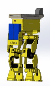
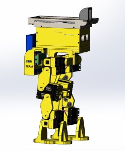
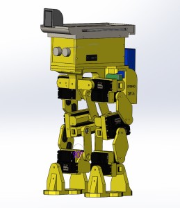
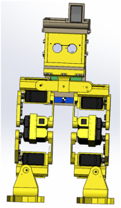
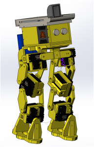
Fall 2016 BiPed : Preliminary Project Plan

Gifty Sackey (Project Manager)

Brandon Perez (Systems Engineer)

Ryan Daly (Electronics and Controls Engineer)

Ijya Karki (Manufacturing Engineer)

Table of Contents

Work Breakdown Structure

Gifty Sackey (Project Manager)

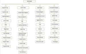
The Work Breakdown Structure (WBS) diagram, shows the responsibilities of each BiPed group member. A top level view of the job requirements can able to found in the product breakdown structure provided below. In each division of the product, readers are provided with a detailed explanation of what each team member will be responsible for their part.

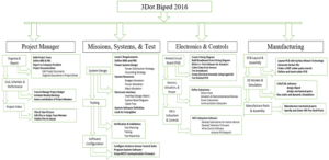
final-wbs-tree-diagram

Figure 1 : Work Breakdown Structure

Product Breakdown Structure

The Product Breakdown Structure (PBS) outlines what products are required to be designed by each group over the course of the semester. The PBS is broken down into a consecutive algorithm in order to ensure a successful completion of the product. Note that the blocks, containing what is produced, are not limited to intervention by other team members. The block labeling allows for a broad overview of what each members responsibilities are without going into details of each product.

product-breakdown-structure

Figure 2 : Product Breakdown Structure

 Project Schedule 

The project schedule details the necessary work that needs to done to implement the BiPed. In addition to the schedule, a projected timeline of deadlines and dates can also be found. In the link provided, readers can find a visual presentation of what the proposed schedule for implementing the BiPed. ProjectLibre was the tool used to implement the schedule. By manipulating the dates provided, if we are able to refine and solidify our requirements early, it gives us more flexibility with our days for coding; validation tests and also unforeseen events.

https://drive.google.com/file/d/0BzIcuzRpcmk4T3ZYX20wUmlPUmM/view?usp=sharing

Burn down and Project Percent Completion

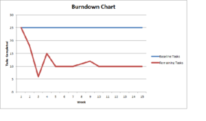
The project percent completion and burn down chart provides a visual representation of the tasks that needs to be completed for the BiPed. It also allows the team to know how much of the current work load has been done.

breakdown-chart

Figure 3 : Breakdown Chart

Project Cost Estimate

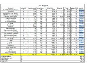
The Cost Report summarizes how much each physical part of our product will cost. Details about shipping are not included in each resource since they can be bundled in the same order when ordering multiple parts from the same vendor. Amazon has no shipping charges if the parts are picked up at our Amazon pickup location at our University. The Project Allocation was determined based off what Rofi, the previous BiPed cost to be initially built.

cost-report-2-1

Figure 4 : Cost Estimates

System Resource Reports

Brandon Perez (Systems Engineer)

Mass Report

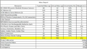
The mass report summarizes an expected mass of our individual physical products of the BiPed. Most of the items were easy to determine since details about most electronic components contain a mass value on their spec sheets or on their vendor’s website. The PLA Platsic mass was determined based off what the previous BiPed weight. All “Actual Mass” values will be determined when obtaining the physical parts. Project Allocation value is an idealistic estimate of what we think the BiPed’s mass should be limited to.

mass-report-2

Figure 5: Mass Report

Power Report

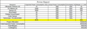
The power report summarizes how much power each electronic component will be consuming. No values shall be needed for the mechanical hardware since power consumption due to kinetic energy will only reflect in the power consumed by our electromechanical devices such as our dc motors and servos. Project Allocation value was determined based off how much constant power our two batteries would supply over the course of an hour.

power-report-5

Figure 6 : Power Report

Spring 2016 RoFi: Project Summary

Christopher Andelin (Project Manager)

Mario Ramirez (Systems Engineer)

Qui Du (Manufacturing Engineer)

Andrew Laqui (Electronics and Controls Engineer)

Henry Ruff (Electronics and Controls Engineer)

Table of Contents

Executive Summary

Program Objectives & Mission Profile

By Christopher Andelin (Project Manager)

RoFi is the fifth prototype from Project Biped.  It is a self-contained, bipedal robot that uses accelerometer feedback to balance. It has 12 DOF (degrees of freedom) and can walk around while avoiding obstacles using an ultrasonic range sensor. A small Android tablet in RoFi’s head provides the brains and an Arduino Mega provides the hardware interface.

The Design

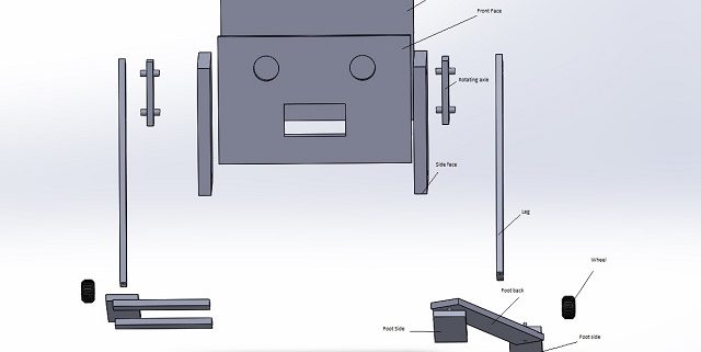
The figures below are our mechanical design and layout of RoFi.
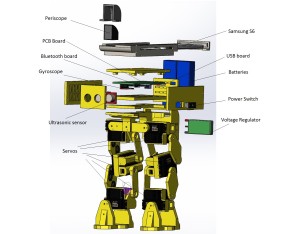
 

Exploded View2

Exploded View

back view

Rear View

Full body

Right Side View

side view

Left Side View


Project Features

Some key features of our design include:

  • Redesigned head
  • Battery Backpack
  • Larger batteries for longer run time
  • SMT PCB / Microcontroller
  • Periscope provides vision
  • RoFi must walk a figure 8 obstacle course

Some innovation of our design include:

  • Mouse pad for shoes
  • Designer glasses box for prototype head due to its ability to be shaped and retain form
  • Servo locks are used to secure loose servos


System Design

System Block Diagram

By Mario Ramirez (Systems Engineer)

The Block diagram shows our system broken into sub-systems and how each sub-system is connected to complete the entire system.  Pins for the Atmega chip can be verified through our interface definitions.
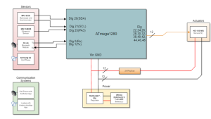
block diagram

System Block Diagram


Experimental Results

Accelerometer / Gyroscope

By Andrew Laqui and Henry Ruff (Electronics and Controls Engineers)

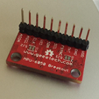
The accelerometer/gyroscope MPU-6050 found here was tested by implementing the test code found here and reading the raw values that were printed through the Arduino IDE. Detailed instructions on how to use those raw values can be found here in Henry Ruff’s blog post.
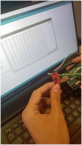
accelerometer-gyroscope_compressed

Accelerometer / Gyroscope


Ultrasonic Sensor

The ultrasonic sensor SEN136B5B was used on RoFi in order to detect and avoid objects. Various tests were performed in order to determine the range for which the sensor can detect. An in-depth explanation of these tests can be found here. The table below details the various angles that the sensor detected an object.

table

Ultrasonic Sensor Data


Servo Driver

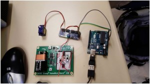
The servo driver PCA9685 found here was tested because originally, an Arduino UNO was going to be used in order to reduce the size of the Arduino. Ultimately, rather than using an Arduino UNO, an ATmega1280 was implemented on the custom PCB design in order to accomplish this size reduction. A detailed description of how to servo driver was tested can be found here.
servo driver_compressed

Servo Driver


Experimental Results

By Mario Ramirez (Systems Engineer)

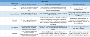
Below is our table of experiments completed.
mario experiments

Experimental Results


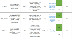
Torque Testing

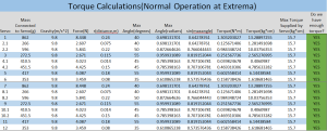
An analysis of the maximum torque needed to move each mass is done to insure RoFi’s servos can provide enough torque before stalling. Further information can be found here, https://www.arxterra.com/spring-2016-rofi-torque-report/.

This table shows the torque needed for each mass compared to the stalling torque of each servo.
torque calc.

Torque Calculations


Center of Mass

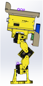
Center of Mass simulation was done to visualize RoFi’s center of mass with the new head design.  The center of Mass is represented by the black and white circle. Further information can be found here, https://www.arxterra.com/spring-2016-rofi-center-of-mass-report/.
center of mass 1

Center of Mass Side View

center of mass 2

Center of Mass Front View

Subsystem Design

Interface Definition

By Mario Ramirez (Systems Engineer), Andrew Laqui  and Henry Ruff (Electronics and Controls Engineers)

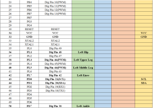
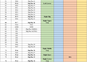
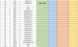
Below is our pin mapping for the ATmega 1280 chip.
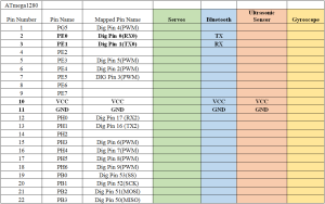
interface definitions 1a

Interface Definitions 1a

interface definitions 1b

Interface Definitions 1b

interface definitions 1c

Interface Definitions 1c

interface definitions 1d

Interface Definitions 1d


Custom PCB / Microcontroller Design

Custom PCB Design

By Andrew Laqui and Henry Ruff (Electronics and Controls Engineers)

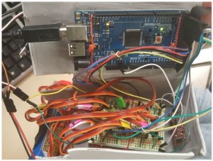
The beginning of the custom PCB design began with taking a look at how messy the physical breadboard was. Due to the number of servos (12), the wires needed to be carefully attached and handled in order to not have any wires disconnect.
messy cables_compressed

Messy Cables

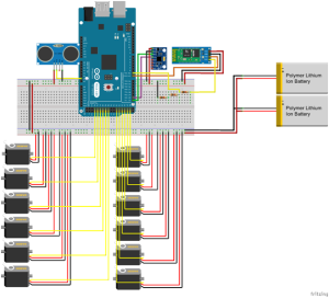
Using the free software Fritzing, a digital diagram of the breadboard was constructed. Various libraries were added to the original software because the free software did not provide a few of the required parts. Those libraries can be found in the links to the Custom PCB Blog below.
fritzing

Fritzing Diagram

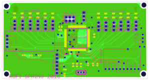
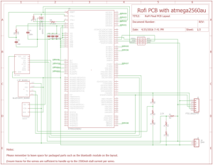
Next, using the free software EAGLE, a schematic was constructed including all of the components that will be used on RoFi according to the interface definitions. The schematic was then used to determine the finalized layout for the actual PCB. More information for the PCB Layout can be found in Qui Du’s PCB Layout blog post.
PCB schematic

PCB Schematic

PCB Schematic 2

PCB Schematic Continued

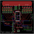
finalized PCB layout

Finalized PCB Layout


Active Balancing of RoFi During Movement

By Henry Ruff (Electronics and Controls Engineer)

A large challenge for RoFi was the utilization of the MPU-6050 Accelerometer/Gyroscope while it was performing its active walking cycle. Because RoFi had to traverse a threshold, incline, and perform a figure-8 on such, it became very time-consuming and difficult to successfully replicate in separate run-throughs. As such, utilization of the MPU-6050 would have been able to make RoFi’s walking more reliable and easier, however, we were unable to successfully implement in. Instead, the following blog post elaborates on relevant efforts.


PCB Design

By Qui Du (Manufacturing Engineer)

I created the PCB layout once I received the PCB schematic from the Electronics and Controls Engineers. More detail about our PCB Design could be found here.


Soldering the PCB

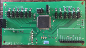
After generating Gerber files and ordering the PCB components, I sent the Gerber files to class president Ryland Watts. One and half weeks later, we received the PCB board and PCB components. I soldered the PCB board with help from the class president Ryland Watts and the manufacturing division manager Juan Mendez. Here is the result of PCB board before and after soldering.
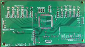
PCB

PCB Before Soldering

PCB After Soldering

PCB After Soldering


Hardware Design

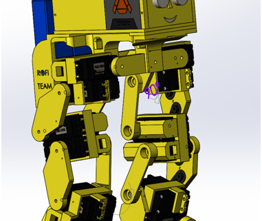
My design decreases the size of the head and feet. Below is the completed SolidWorks 3D modeling of RoFi.
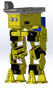
mechanical design

Complete RoFi Design

Detailed information about the design could be found here

After generate the STL files and making STL repair using netfabb Basic, all parts were ready to print. Here is the final result of RoFi.
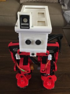
complete rofi_compressed

Complete RoFi


Software Design

Software Block Diagram

By Mario Ramirez (Systems Engineer)

Here is a flow chart of our software.  The grey boxes are scripts written to handle the telemetry.  This code is given to you by Hill.  Blue squares represent the different subroutines for our code.  The red boxes represent the type of pin each sensor or actuator is connected to.  The orange squares represent the name and number of the pin each sensor or actuator is connected to.  The yellow boxes represent our sensors and actuators.  Green boxes represent what the user is controlling based on the software.
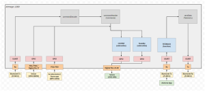
software block diagram

Software Block Diagram


Verification & Validation Test Plan

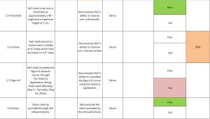
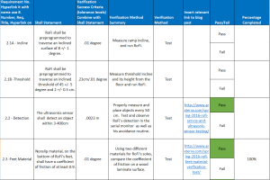
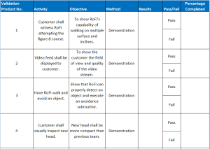
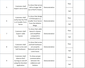
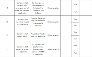
Verification and Validation are based off requirements that can be found here, https://www.arxterra.com/spring-2016-rofi-preliminary-design-documentation/

Note: The Pass / Fail and Percentage Completed columns is our teams opinion and not that of the customer.
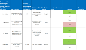
verification and validation req.1a

Verification and Validation Req.1a

verification and validation req.1b

Verification and Validation Req.1b

verification and validation req.2a

Verification and Validation Req.2a

verification and validation req.2b

Verification and Validation Req.2b

verification and validation req.2c

Verification and Validation Req.2c

verification matrix 1a

Verification Matrix 1a

verification matrix 1b

Verification Matrix 1b

verification matrix 1c

Verification Matrix 1c


Project Update

Work Breakdown Structure

By Christopher Andelin (Project Manager)

Below is our work breakdown structure.
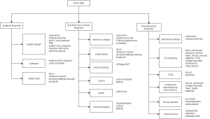
CDR WBS

Work Breakdown Structure


Resource Reports

Mass Report

By Mario Ramirez (Systems Engineer)

Project allocation is based off of the maximum mass the servos would be capable of moving before stalling.
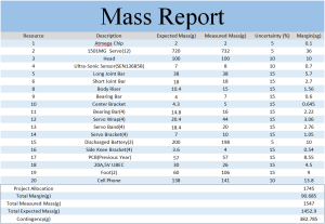
mass report

Mass Report


Power Report

Project allocation is based off of a 15 minute run time.  This report assists in calculating what ratings you need for the batteries.

power report

Power Report


Budget Report

By Christopher Andelin (Project Manager)

Note: Our project cost does not include the PCB / Microcontroller and the components because our President bought them.

cost estimate

Project Cost


Schedule

Below is our project schedule.

View post on imgur.com

Schedule Summary

Here is my assessment on our overall progress:

  • Mechanical Design 100% 
  • PCB / Microcontroller Design 100% 
  • Repaired issues with loose frame 90%
  • Improved running time 100%
  • Periscope lens 100%
  • Polyfuse SMT 100%
  • Organize cables 100%
  • Moving parts hazard 0%
  • Walking in a circle on flat surface 100%
  • Surpass leveled surface to inclined surface threshold 100%
  • Walking in a circle on inclined surface 25%
  • Figure 8 obstacle course 30% (leveled surface circle only)

My overall assessment is that we are about 80% complete.


Burndown Chart

Our burndown chart dips in the last week due to getting the printed parts and PCB / Microcontroller implemented into our design.  We still need to complete the figure 8, hence the reason why we are behind schedule.
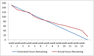
burndown chart

Burndown Chart


Concluding Thoughts

Since it is the end of the semester, I have some suggestions for future RoFi teams:

  • Get approval for all purchases – Due to time constraints, our team was in a rush to get parts in to begin implementation.  We focused our attention on completing our mission objective without considering our customers expectations.  It is important to complete the objective as well as pleasing the customer.
  • Replace servos with better quality – We had servo issues throughout the semester. We always had a spare servo in hand due to the unpredictability of servo failure.
  • Make RoFi lighter – The servos would spasm causing RoFi to fall.
  • Lower the center of mass – Due to RoFi being so top heavy, it was difficult implementing walking on an inclined surface.
  • Avoid using Robot Poser – Robot Poser only worked on one of our team members laptops and we never found out why.  Robot Poser was also difficult to get it to start.  You may have to open task manager at times and close programs, plug and unplug the Arduino cable and the battery; I felt like we had to jump through hoops to get it to work.
  • Implement the ultrasonic sensor, accelerometer/gyroscope and cordless walking – Due to customer request, we focused a lot of our attention getting RoFi to walk the figure 8 obstacle course and neglected other features.
  • Get RoFi asap – We had to do a lot of documentation throughout the semester, we did not get to work on RoFi until about one month into the semester.
  • Choose team members wisely – I was fortunate to have a great team but keep in mind that students have other classes and work to attend to.  Interview students and select members that have time, transportation and money.
  • Project Manager – As Project Manager I had a lot of paperwork in the beginning of the semester. Work slowed down in the third month, so I dedicated a lot of my time getting RoFi to walk and assisted the engineers where I could.
  • Be cautious of free 3D printing – Verify that the quality of the 3D printing material is to your liking.
  • Understanding the customer – Realize that the customer has multiple projects and classes and will claim things were said or were not said that you may need to address.  Communicate and verify all concerns with the customer, student teacher and president.
  • Update Mission Objective – Our mission objective said that the incline was 8 and 6 degrees;  we measured the incline and it varied from 14 to 7 degrees.  The room was also a burden to work in because the room was popular for labs and lectures.


Resource

Project Video

Bonus Videos

www.youtube.com/watch?v=96UEVOszRBs

Files

The following Google Drive contains useful resources for future RoFi teams, https://drive.google.com/drive/folders/0B_v74PMhdCbKSXVPQ285ekZEX28.

Spring 2016 RoFi: Research and Implementation of the Accelerometer/Gyroscope

Christopher Andelin (Project Manager)

Mario Ramirez (Systems Engineer)

Qui Du (Manufacturing Engineer)

Andrew Laqui (Electronics and Controls Engineer)

Henry Ruff (Electronics and Controls Engineer)

Research and Implementation of the Accelerometer/Gyroscope

By Henry Ruff (Electronics and Controls Engineer)

Note: All files referenced without additional links can be found in the RoFi Spring 2016 Google Drive, https://drive.google.com/drive/folders/0B_v74PMhdCbKSXVPQ285ekZEX28.
RoFi’s movement is somewhat inconsistent, and as such, it is unreliable in being able to perform the same exact frames that it was able to perform from a previous trial; a solution to this inconsistency is the implementation of the MPU-6050 accelerometer/gyroscope, as an ideal albeit very optimistic task. The  MPU-6050 would allow RoFi to be able to balance itself through normal runs, on different surfaces and inclines, all using the same walking code.

In order to be able to start any of these possibilities, research was done on implementation of the MPU-6050. The following Arduino guide is used to obtain raw, readable values with the device.

http://playground.arduino.cc/Main/MPU-6050.

However, this is not a usable format. Instead, Jeff Rowberg had created files for utilization of the readings from the MPU-6050. The tutorial used in being able to work with these files is found here, http://diyhacking.com/arduino-mpu-6050-imu-sensor-tutorial/. Just in case, the necessary Arduino libraries that are used can also be found with the rest of the RoFi files.

Please note, a common complication that can arise in compiling this code is if any Arduino libraries get included before the initial comments in Rowberg’s code. The desired types of values can be toggled by commenting and uncommenting different modes of output.


For RoFi’s purposes and to optimize the code as much as possible, I have trimmed down Rowberg’s code to only what might be used, and this version is shown in the “MPU6050Code.txt” file found in the Google Drive. This file is meant to provide the chunks of Rowberg’s code that should be placed into RoFi’s normal walking code generated from Robot Poser, and instructions for which are found within the file itself.

Now that the code has been integrated into RoFi’s walking code, it can theoretically be used to assist in its balancing. The main considerations that we were able to come up with in doing this were as follows:

  • Previous semesters had only utilized the MPU-6050 while RoFi was stationary.
  • As RoFi is walking, the MPU-6050’s data would need to be referenced between each frame of motion.
  • RoFi’s head does not stay parallel to the ground while walking, instead it turns in every direction except rotation about the z-axis. This means the gyroscope is fine for the z-axis, but complex for the other two. If RoFi’s head can be kept parallel, this problem can be circumvented.
  • With the values being read, they can be compared to an expected set of values for RoFi’s normal movement. However, this would need a very large file containing ideal gyroscope values, and the Arduino is not able to reference external files, and there is the concern of limited memory on the Arduino Mega.
  • RoFi’s head movement is too erratic and jerky to use the accelerometer for comparisons with how our current walking code performs. (This can be observed in walking videos.) Similarly, this prevents the gyroscope by comparing values that are being read to each previous value.
  • An acceptable range of variation cannot quite be determined with RoFi’s current movement, to be used in making RoFi balance itself.
  • RoFi’s balance while walking is not as simple as moving one servo a few degrees, rather, most frames of movement utilize several servos, and even one degree on each can overthrow its balance.

With these considerations, the progress we were able to make is simply this suggested code “MPU6050Control.txt”, (in the Google Drive) for future semesters and a guideline for potential ways to use the MPU-6050 to actively balance RoFi during motion.

Spring 2016 RoFi: Mechanical Design Rev. 3

Christopher Andelin (Project Manager)

Mario Ramirez (Systems Engineer)

Qui Du (Manufacturing Engineer)

Andrew Laqui (Electronics and Controls Engineer)

Henry Ruff (Electronics and Controls Engineer)

Table of Contents

Final RoFi 3D Modeling

Qui Du (Manufacturing Engineer)

Introduction

In Mechanical Design Rev2, https://www.arxterra.com/spring-2016-rofi-mechanical-design-rev-2/ RoFi’s head contains both the PCB and Arduino Mega.

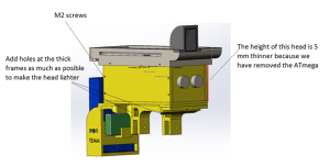
I redesign the head to contain the PCB because my team implemented the Arduino Mega chip onto the PCB board. I also, changed to a smaller size screw for the head from M3 to M2. Since the size of the head covers is 5mm thick, having smaller screw holes give the frame more strength and they make the head look cleaner. Weight is also important therefore, I made the head as light as possible by carving holes, curving parts, and made some parts thinner.

figure 1

Figure 1: Head Update

figure 2

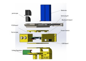
Figure 2: Exploded View


Additional frames updated

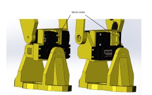
Some of the servos come loose because they slide into the frame and do not attach to the frame; to fix this problem, I designed servo locks to lock the loose servos into place.

figure 3

Figure 3: Loose Servo

figure 4

Figure 4: Servo Lock


Mass Report Update

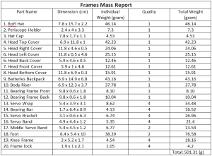
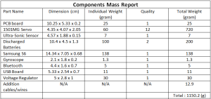
My new mechanical design has a mass of 1651.51 g which is below the mass report allocation of 1745 g found here, https://www.arxterra.com/spring-2016-rofi-preliminary-project-plan/. We prefer lower mass because our current mass in conjunction with our low quality servos, RoFi tends to spasm which causes RoFi to fall over.

figure 5

Figure 5: Mass Report of RoFi’s Frame

figure 6

Figure 6: Components Mass Report

figure 7

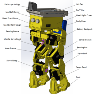
Figure 7: Part Name Label


Completed Design

Note: The Arxterra Logo is just for decoration and will not be on the final product.

figure 8

Figure 8: Bonus RoFi Design

All SolidWorks 3D modeling parts and assembly can be found here, Google Dive Link

Disclaimer: All parts were created in SolidWorks 2016; older versions of SolidWorks might not open the files. I included the STL files to allow students with older version of SolidWorks to view or print parts.

Spring 2016 RoFi: Finalized Fritzing Diagram, PCB Design, Alternative Arduinos, and Custom Eagle Components

Christopher Andelin (Project Manager)

Mario Ramirez (Systems Engineer)

Qui Du (Manufacturing Engineer)

Andrew Laqui (Electronics and Controls Engineer)

Henry Ruff (Electronics and Controls Engineer)

Table of Contents

Finalized Fritzing Diagram

By Andrew Laqui (Electronics and Controls Engineer)

The Fritzing software, found here , allowsa physical breadboard design to be created digitally. By designing a digital version, the beginning PCB designs can begin. One difficulty with using the free software is that the library does not have all the parts needed for many designs. Using Google, many of the parts required were found with Github.

Here are links to the Fritzing libraries for RoFi:

https://github.com/adafruit/Fritzing-Library (If using the Adafruit Servo Driver)

https://github.com/RafaGS/Fritzing (For the Bluetooth Module HC-06 and Accelerometer/Gyroscope MPU-6050)

figure 1

Figure 1: Fritzing Diagram

The image below shows what the PCB will be replacing. Just having twelve servos without any of the other components creates quite a messy board; especially on the Arduino MEGA, wires would often come out and cause a servo to stop working. The new PCB allows the servos to be easily plugged in while keeping the wires from becoming tangled.

figure 2_compressed

Figure 2: Prior to PCB Implementation


PCB Design

By Andrew Laqui and Henry Ruff (Electronics and Controls Engineer)

Due to the requirement to use a smaller Arduino microcontroller than the Arduino MEGA, we originally thought that we had to implement something like the Arduino Uno or Nano. We were later informed that rather than designing a shield as our printed circuit board for the Arduino, we could implement the chip used in the MEGA. After learning that the ATmega1280 is the correct chip to use to control RoFi, the group decided that this would a great way to design our PCB; the PCB design was challenging while also allowing us to continue to use the software made available on the Project.

RofiPCB

Figure 3: PCB Schematic

RofiPCBServos

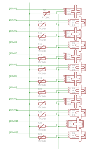
Figure 4: Servo Schematic

Figure 5: Interface Definitions

For the ATmega1280 itself, the footprint and pin connections are identical to the ATmega2560, and so this was able to be used for the EAGLE layout. Necessary protection circuits were included by following the schematic from Arduino’s website, but an additional 6-pin header was added for the bootloader necessary for the chip. A 6-pin header was added for the FTDI component, which would be used to allow for the USB port to be programmable. Additionally, there are two separate voltage divider circuits, one to allow for the 3.3V that the Bluetooth and MPU-6050 use, and one for the RX line of the Bluetooth. A simple 3-pin header is used for the power input, coming from the external voltage regulator that is connected to the batteries.

Once the interface definitions were developed, connecting the pins using EAGLE was simple. In order to keep the EAGLE schematic looking neat and legible, we used a second page for the servos. By changing the name of the wires, the wires can be connected across different pages. It is important when changing the name of the wires to put a note on the wire that is being named so that the pins from the ATmega1280 are clearly shown. Another issue we were having was that on the second page with the servos, a few of the VCC and GND wires looked like they were connected to the servo, but in reality, they were not actually connected. Once we were sure that all of the pins were connected properly, the layout was easily completed.


Alternative Arduinos

By Henry Ruff (Electronics and Controls Engineer)

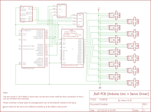
For the option of using an Arduino board aside from the Mega, there are some considerations. First of all, there will not be enough pins to accommodate all of the sensors and the 12 servos, so a servo driver would be needed for the servos. An early PCB design utilized the Adafruit 16-Channel 12-bit PWM/Servo Driver, as shown in the following image.

RofiPCBUno

Figure 6: Arduino Uno and Servo Driver Schematic

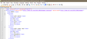
However, further complications were found when working with Robot Poser. The source code was never made available, so there was no room for modifications. The real problem was in the “Rofi.RobotProfile” file that Robot Poser uses, there is direct addressing of pins that can only be found on an Arduino Mega.

PoserExtraFile

Figure 7: Robot Profile

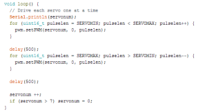
In the servo driver code, its method of addressing a particular servo is by using a variable, as shown in Figure 8. This conflicts with the method that Rofi.RobotProfile uses, and since Robot Poser itself cannot be modified, using anything but the Arduino Mega while also using Robot Poser is simply not possible. These complications were primary factors leading to us implementing the ATmega1280 chip directly onto the PCB instead of using a different Arduino.
ServoDriverCode

Figure 8: Servo Driver Code


Custom Eagle Parts

By Henry Ruff (Electronics and Controls Engineer)

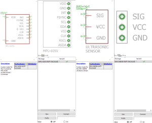
To simplify the PCB design and make it easier for future renditions of RoFi, we created custom EAGLE components for the Invensense MPU-6050 Accelerometer/Gyroscope and the SEN136B5B Ultrasonic Sensor. The former has a space laid out for it to be placed directly above the PCB, while the latter is ideal at the edge of the PCB as it can stick out due to its right-angle headers. These files were consolidated into a custom RoFi library that can be added to EAGLE, and is available below.

CustomEagleComponents

Figure 9: Customer Eagle Components

Spring 2016 RoFi: Google Drive

Spring 2016 RoFi: PCB Layout

Christopher Andelin (Project Manager)

Mario Ramirez (Systems Engineer)

Qui Du (Manufacturing Engineer)

Andrew Laqui (Electronics and Controls Engineer)

Henry Ruff (Electronics and Controls Engineer)

Table of Contents

PCB Layout

Qui Du (Manufacturing Engineer)


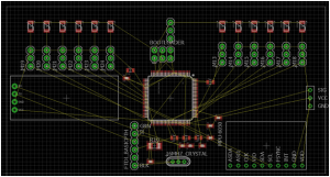
Once I received the PCB schematic from the Electronics and Controls Engineers, I create the PCB layout.

First, I clicked on the Generate/Switch to board  button button at the top left corner of the schematic window. Then I clicked Yes on the Warning window to confirm that we will create a PCB layout from the schematic. The below window will appear:

figure 2

Figure 1: Generate/Switch to Board


Adjust PCB Board Size

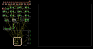
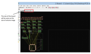
I designed the PCB board the same size as the Arduino Mega (101.6 X 53.33mm) to allow the user to interchange the PCB with the Arduino Mega in RoFi’s head. To adjust the PCB board size, first I turned grid on by clicking the Grid button → changing the Unit to mm → selecting On at Display → and then by clicking Ok. Then I clicked on the top right corner of the white rectangular and adjusted the until shape until it reached 101.6mm X 53.33mm.

figure 2

Figure 2: Turn on Grid Display and change unit length

figure 3

Figure 3: Adjust the size of PCB board


Visualize and Understand PCB Design

figure 4

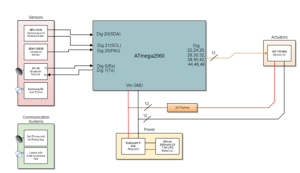
Figure 4: System Block Diagram with Arduino Mega

Since our level one requirement requires that we not use the Arduino Mega; we installed the ATmega1280 chip onto our PCB board. We still need to adjust the pin mapping from the ATmega2560 board to the ATmega1280 chip on the system block diagram. More information can be found at, https://www.arduino.cc/en/Hacking/PinMapping2560.


Component placement

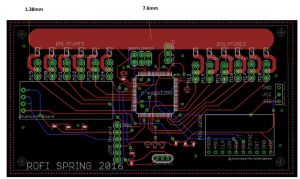
The power trace takes up a lot of space on our PCB, therefore, it is better to isolate the power supply with other components.  In my design, I placed the power trace on the top border of the PCB board.

I began placing the ATmega chip, Bluetooth, USB chip, Accelerometer/Gyroscope onto the board and placed all the supporting components around them. Then I used smash features to smash and delete unimportant names on the PCB layout.

figure 5

Figure 5: PCB Component Placement


Make a Ground Plane and Copper Pours

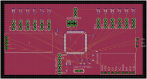
Apply polygon on top layer.

figure 6

Figure 6: Draw Polygon on Top Layer

Next click the Ratsnest button to view the ground plane.

figure 7

Figure 7: Top Layer Ratsnest Results

Apply Polygon in bottom layer.

figure 8

Figure 8: Polygon Applied to Bottom Layer

Click Ratsnest button.

figure 9

Figure 9: Bottom Layer Ratsnest Results


Draw a Wire Signal

Determine a current width trace

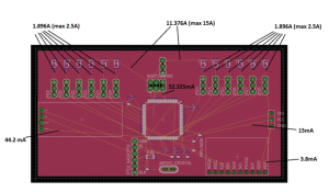
According to our power report found here, https://www.arxterra.com/spring-2016-rofi-preliminary-project-plan/ each servo can draw up to 1.896A.

figure 10

Figure 10: Current Draw

Since we plan to order our PCB board from www.4pcb.com, I used the trace width calculator from their website to determine the trace width of each wire.

Note: The thickness of the trace cannot be adjusted in Eagle CAD. We can order the trace thickness when we send the PCB layout to the PCB fabrication house. In our PCB layout, we ordered a 2 oz/ft^2 thickness.

figure 11

Figure 11: Required Trace Width

figure 12

Figure 12: Visual of Current Trace Width


DRC Check

Each PCB fabrication house has its own set of design rules, since we are using www.4pcb.com to fabricate our PCB, we followed their design rules.

4pcb Fabrication House DRC Check

Step 1

Download the DRC file by going to,  http://colinkarpfinger.com/blog/2010/ordering-pcbs-designed-with-eagle/.

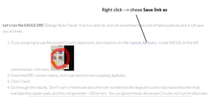
Right click typical_4pcb.dru → choose Save link as → Save the file

figure 13

Figure 13: Right Click typical_4pcb.dru

Step 2

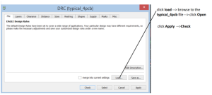
The window below appears once the DRC check icon is selected in the board window.

figure 14

Figure 14: DRC Window

figure 15

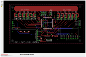
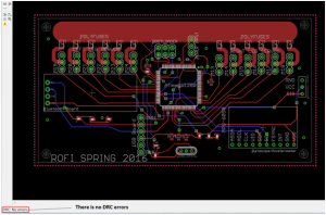
Figure 15: No DRC Error in our PCB Layout


Create Gerber Files

Step 1

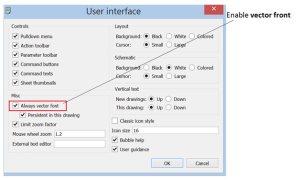
Enable vector front by going to Option → User Interface → check Always vector front → OK

figure 16

Figure 16: Enable Vector Front

figure 17

Figure 18: Select CAM Processor

Open the CAM job → choose the CAM job file → click Open → click Process Job to generate Gerber files.


Get PCB Layout Quote From Fabrication House

After I zipped all the Gerber files and uploaded them to, www.4pcb.com, I received the PCB Layout Quote.

figure 18

Figure 19: PCB Layout Quote from www.4pcb.com


Spring 2016 RoFi: Bluetooth Verification Test

Christopher Andelin (Project Manager)

Mario Ramirez (Systems Engineer)

Qui Du (Manufacturing Engineer)

Andrew Laqui (Electronics and Controls Engineer)

Henry Ruff (Electronics and Controls Engineer)

Bluetooth Verification Test

Mario Ramirez (Systems Engineer)

Test Objective

To verify that a Bluetooth module, HC-06 and a cell phone are able to communicate within a distance of 10 feet +/- 0.5 feet.

Tools

Figure 1 indicates that a measuring tape is needed to verify this test.

figure 1

Figure 1: Measuring Tape

Preliminary Info

Bluetooth code: https://drive.google.com/drive/my-drive

Bluetooth Circuit

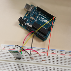
Figure 2 shows how to connect the Bluetooth to the Arduino for this test.

figure 2

Figure 2: Fritzing Diagram

Procedure

Setup the Bluetooth module, Arduino and a LED.  Verify that the code is uploaded to the Arduino and begin.

1.Lay the measuring tape and create a distance of 10 feet.

figure 3_compressed

Figure 3: Measure Distance

2. Starting at 1 foot away from LED, turn the LED on and off with your phone to insure you are connected.

3. Move away 0.5 feet and again turn the LED on and off to insure you are connected.

figure 4_compressed

Figure 4: Turn LED on and off while moving back

4. Repeat step 3 until you reach 10 feet.

figure 5_compressed

Figure 5: Turn LED on and off at 10 feet

Results

Figure 6 is a table of my results.

figure 6

Figure 6: Results

In our requirements the Bluetooth module must have a range of at least 10 feet; from our verification test, we have met this requirement.  Trial 4 was a test to verify our max range and 27 feet was the maximum range we could physically move away from the Bluetooth module while remaining in the same room.

Spring 2016 RoFi: Bluetooth Communication

Christopher Andelin (Project Manager)

Mario Ramirez (Systems Engineer)

Qui Du (Manufacturing Engineer)

Andrew Laqui (Electronics and Controls Engineer)

Henry Ruff (Electronics and Controls Engineer)

Bluetooth Communication

Mario Ramirez (Systems Engineer)

To meet requirement 1.8, RoFi must communicate with the Arxrobot App and have an on and off state using the users phone.  Begin your Bluetooth connection by downloading the Arxrobot firmware, https://github.com/arxterra/BiPed-Robot.  This code has the commands and command decoder subroutine to control RoFi using the Arxrobot app.

First, connect and setup your Bluetooth mode, HC-06.  The pass code for connecting to the module with your phone is ‘0000’.

figure 1

Figure 1: Bluetooth Fritzing Diagram


figure 2

Figure 2: Bluetooth Fritzing Schematic

Within the Arxrobot firmware a custom command will be made.

figure 3

Figure 3: Arxrobot Custom Command

To initially test the custom command, a simple LED on and off command will be implemented within the command decoder subroutine.

figure 4

Figure 4: LED Subroutine

Once proper Bluetooth connection is tested, change the implemented command to your desired action.  For RoFi, we created a trigger after the command is received.

figure 5

Figure 5: Trigger Command

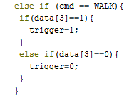
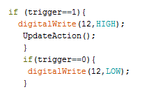
When the command packet is sent, the code will then read the 3rd byte.  If the byte is HIGH it will set trigger to HIGH.  If the byte is LOW it will set trigger to LOW.  Using this trigger variable, an “if” statement was implemented into our main loop code.

figure 6

Figure 6: HIGH or LOW Command

Figure 6 shows two “if” statements for different values of the trigger.  When the trigger is HIGH, it will light an LED and put RoFi into an Update Action subroutine which allows RoFi to update to its next frame.  When trigger is set to LOW, RoFi will not take any action and will remain at its current frame until trigger is set back to HIGH.

Spring 2016 RoFi: Calibration

Christopher Andelin (Project Manager)

Mario Ramirez (Systems Engineer)

Qui Du (Manufacturing Engineer)

Andrew Laqui (Electronics and Controls Engineer)

Henry Ruff (Electronics and Controls Engineer)

Calibration

Mario Ramirez (Systems Engineer)

Introduction

Before attempting to walk with RoFi, a calibration test must be done.  Using Robot Poser, Jonathan’s instructions and the calibration file (located below), perform the needed test and create your own calibration file.  This file will be RoFi’s starting/zero position for each routine in the future.  All future angles will be in reference to these zero frames.

Robot Poser:  http://www.projectbiped.com/prototypes/rofi/programs/robot-poser

This download includes the calibration file.

Jonathan Dowdall’s instructions: https://docs.google.com/document/d/1H0iGTlUO-VljwtqiN5W3QWxoLYYhNEEphhULrg87Wgc/edit

Blender File for RoFi calibration:

https://docs.google.com/file/d/0By_h1KTMNaWNcmlMS0FNWGJ5OVE/edit

This post is in reference to, https://www.arxterra.com/bipedal-robot-calibration/.

Our team’s calibration

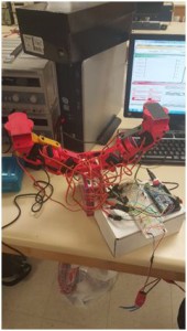
Figure 1 shows RoFi in High Roll Position.

Figure 1: High Roll Position

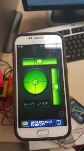
Figure 2 shows that RoFi’s foot is level.

figure 2_compressed

Figure 2: Verifying Level Foot

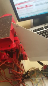
Figure 3 shows RoFi’s leg is perpendicular to the table.

figure 3_compressed

Figure 3: Verifying Perpendicular Leg

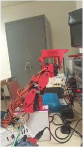
Figure 4 shows RoFi in High Position.

figure 4_compressed

Figure 4: High Position


Spring 2016 RoFi: Feet Material Verification Test

Christopher Andelin (Project Manager)

Mario Ramirez (Systems Engineer)

Qui Du (Manufacturing Engineer)

Andrew Laqui (Electronics and Controls Engineer)

Henry Ruff (Electronics and Controls Engineer)

Table of Contents

Feet Material Verification Test

Mario Ramirez (Systems Engineer)

Requirement

Nonslip material on the bottom of RoFi’s feet shall have a friction coefficient of 0.9 +/- 0.05.

Test Objective

To verify that the material on the bottom of RoFi’s feet has a friction coefficient of 0.9 +/- 0.05 with a laminated podium.

Tools

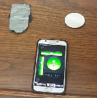
Figure 1 shows the tools I used to calculate the friction coefficient of RoFi’s shoes.

figure 1

Figure 1: Tools

Preliminary Calculations

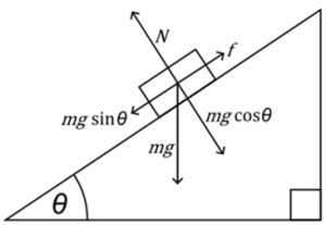
Figure 2 indicates the vectors involved in my experiment.

figure 2

Figure 2: Incline Vectors  http://i.stack.imgur.com/lMCD8.png

μ = friction coefficient

Equation threshold where static object begins to move: m*g*sin(theta) = μ*m*g*cos(theta)

Procedure

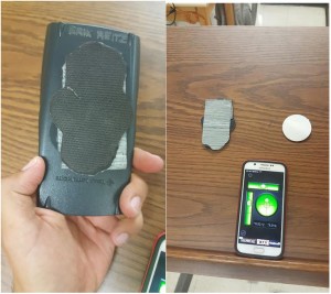
Step 1: Weigh desired mass and attach non-slip material.


figure 3_compressed

Figure 3: Mouse Pad Attached to Mass

Step 2: Place mass and material on an incline.

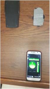
figure 4_compressed

Figure 4: Starting Location and Angle

Step 3: Tilt surface until slipping occurs and record the angle.

figure 5_compressed

Figure 5: Mass Slipped

Step 4: Calculate friction coefficient using equation.

Results

A second material was tested along side the mouse pad to show a difference in friction coefficients.

figure 6

Figure 6: HD Non-Slip Pad

figure 7

Figure 7: Mouse Pad

Reference

http://www.physicsclassroom.com/class/newtlaws/Lesson-2/Types-of-Forces

http://physics.stackexchange.com/questions/243717/why-does-something-on-an-inclined-plane-move-forward-at-all