Spring 2016 RoFi: Servo Testing and Centering

Christopher Andelin (Project Manager)

Mario Ramirez (Systems Engineer)

Qui Du (Manufacturing Engineer)

Andrew Laqui (Electronics and Controls Engineer)

Henry Ruff (Electronics and Controls Engineer)

Servo Testing and Centering

Henry Ruff (Electronics & Control)


Considering RoFi’s provided condition is questionable, we decided to verify that each servo was still in working condition, and able to perform in its given ranges. The servos being used are the Power HD 1501-MG, and the datasheet for which is provided below.


https://www.pololu.com/file/download/HD-1501MG.pdf?file_id=0J729


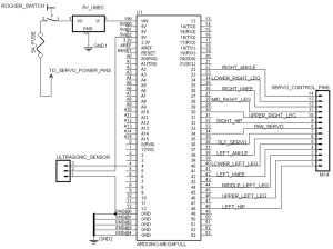
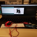
According to this datasheet, each servo has a range of motion of 165 degrees, and so for our purposes I modified the following code to sweep the servo arm in a range of 0 to 180, pause, and then sweep back from 180 to 0. This test was performed on each servo individually, using the schematic and setup provided below as well.

ServoTest_compressed

Image 1: Servo Test

ServoCentering

Image 2: Servo Centering

/* Sweep

by BARRAGAN <http://barraganstudio.com>

This example code is in the public domain.


modified 8 Nov 2013

by Scott Fitzgerald

http://www.arduino.cc/en/Tutorial/Sweep


Modified By Henry Ruff

*/


#include <Servo.h>


Servo myservo;  // create servo object to control a servo

// twelve servo objects can be created on most boards


int pos = 0;    // variable to store the servo position


void setup() {

myservo.attach(5);  // attaches the servo on pin 5 to the servo object

}


void loop() {

for (pos = 0; pos <= 180; pos += 1) { // goes from 0 degrees to 180 degrees

// in steps of 1 degree

myservo.write(pos);              // tell servo to go to position in variable ‘pos’

delay(15);                       // waits 15ms for the servo to reach the position

}

delay(2000);

for (pos = 180; pos >= 0; pos -= 1) { // goes from 0 degrees to 180 degrees

// in steps of 1 degree

myservo.write(pos);              // tell servo to go to position in variable ‘pos’

delay(15);                       // waits 15ms for the servo to reach the position

}

delay(2000);

}

The results of running the code for each servo is shown below. The numbers assigned to each servo was for testing purposes only, and differs from how they are actually assembled into RoFi. Servos that did not perform as expected were noted as such, and therefore set to be replaced if necessary.

ServoTable

Table 1: Servo Results

Modification to this code (shown below) was used to center the servos, following the method that Jonathan Dowdall outlines on his Project Biped website. Once a servo is centered by using the code, it is assembled into RoFi using the image below that is also on the website, and is then ready to be used in other steps.

ServoAssembly

Image 3: Servo Assembly Source:https://docs.google.com/presentation/d/1bLCdCVLSEdNJ1TqWfmgMjQWJXn9XuLbbaKUQzWxhx_E/edit?pref=2&pli=1#slide=id.i6


/* Sweep

by BARRAGAN <http://barraganstudio.com>

This example code is in the public domain.


modified 8 Nov 2013

by Scott Fitzgerald

http://www.arduino.cc/en/Tutorial/Sweep

*/


#include <Servo.h>


Servo myservo;  // create servo object to control a servo

// twelve servo objects can be created on most boards


int pos = 0;    // variable to store the servo position


void setup() {

myservo.attach(5);  // attaches the servo on pin 5 to the servo object

}


void loop() {

for (pos = 0; pos <= 90; pos += 1) { // goes from 0 degrees to 180 degrees

// in steps of 1 degree

myservo.write(pos);              // tell servo to go to position in variable ‘pos’

delay(15);                       // waits 15ms for the servo to reach the position

}

delay(20000);

}


Spring 2016 RoFi: Torque Report

Christopher Andelin (Project Manager)

Mario Ramirez (Systems Engineer)

Qui Du (Manufacturing Engineer)

Andrew Laqui (Electronics and Controls Engineer)

Henry Ruff (Electronics and Controls Engineer)

Torque Report

Mario Ramirez (Systems Engineer)

Method

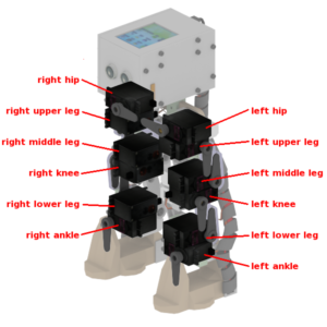
Image below is used for the purpose of identifying the servo location.  This photo does not necessarily represent our group’s final product.

image 1

Image 1:Picture taken from Jonathan Dowell: http://www.projectbiped.com/prototypes/rofi/photos


Torque was calculated using the equation T=rFsin(theta). The distance between the servo and the end of the mass being moved (r) was calculated using a measuring tape.  The range of motor was calculated using a protractor (theta) and the weight being moved was taken using a scale (F).   Once the torque was calculated, it was compared to the stalling torque of the servo.  The following 2 tables show the calculations and the comparison of the torque needed and the stalling torque.

Torque Calculations

The table below shows the amount of torque needed to move the mass connected to each servo.  Numbers stated similar to 2.1 and 2.2 represent if the servo were to be moving the mass above or below it.  The measurements and calculations were taken for both top and bottom to insure the customer that the servos could move both top and bottom mass if needed. The table represents the worst conditions (extreme case) for RoFi, this means, that the angle of all the lever arms in respect to their servos are at a 90 degree angle thus needing the most torque of any other position.  The table shows that in a worst case scenario servos 1 and 7, the feet servos, will fail.

table 1

Table 1: Torque Calculations (If Things go Wrong)


The table below shows the calculations for RoFi under normal conditions.  This table uses the max angle of RoFi’s lever arms based on his normal operation.  If normal operation is maintained we can see from the table that each servo is capable of supplying enough torque to move its respective mass.

Table 2: Torque Calculations (Normal Conditions)


Spring 2016 RoFi: Mechanical Design Rev.1

Christopher Andelin (Project Manager)

Mario Ramirez (Systems Engineer)

Qui Du (Manufacturing Engineer)

Andrew Laqui (Electronics and Controls Engineer)

Henry Ruff (Electronics and Controls Engineer)

Table of Contents

Mechanical Design

Qui Du (Manufacturing Engineer)

Objectives for this Design

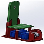
RoFi is the fifth prototype from Project Biped. It has twelve degrees of freedom and can walk around while avoiding obstacles using an ultrasonic range sensor. A small Android phone in RoFi’s head provides the brains, an Arduino Uno provides the hardware interface, and batteries to power the servos. By reading the “RoFi- Next Generation Head- DAREL” project designed by Mike Pluma, I think this is a good design for our Rofi; therefore, I used this design for our RoFi head.

Body base design planning

figure 1


Sources:

http://web.csulb.edu/~hill/ee400d/Project%20Folder/Robots%20and%20Drones/BiPed%20Robot/RoFi%20Project/

https://www.adafruit.com/datasheets/arduino_hole_dimensions.pdf

http://www.hobbyking.com/hobbyking/store/__9493__Turnigy_1300mAh_3S_30C_Lipo_Pack.html

http://www.seeedstudio.com/wiki/index.php?title=Ultra_Sonic_range_measurement_module

SolidWorks Modeling Design

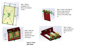
Step 1: determine dimensions of the body base

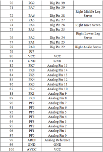
Long dimension of  body base ≥ width dimension of phone base + (2*width dimention of battery) + width dimension of ultrasonic sensor +dimensions of two walls.

Long dimension of body base ≥ 20 + (2*34) + 15 + 10 = 109; however, we need space for wires and extra items, the long dimension of body base is 114 mm.

Width of body base ≥ long dimension of battery = 78, since the long dimension of a battery  has a largest scale to be place in the body base; therefore I round width dimension of body base to 80 mm.

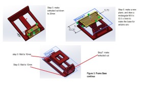
Step 2: SolidWorks model for body base

figure2

figure 3

Note: plane2 was added to make an extend space (5mm)  for the phone bracket.

Drawing diagram

Frame base2


Step 3: SolidWorks Prototype of batteries

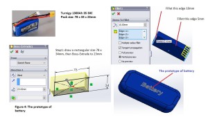
For our projects,  the battery type is the last item to be chosen, however, to make my body base design more realistic, I chose the battery type from last semester as an prototype of this design.

Battery Turnigy 1300Ah 3S 30C. Dimensions: 78 x 34 x 23mm

Source: http://www.hobbyking.com/hobbyking/store/__9493__Turnigy_1300mAh_3S_30C_Lipo_Pack.html

figure4

Step 4: SolidWorks prototype for Arduino Mega

Arduino Uno has dimensions: 68.6 x 53.3 x 2mm

Source: https://www.adafruit.com/datasheets/arduino_hole_dimensions.pdf

figure 5


Step 5: SolidWorks prototype for Ultrasonic Sensor

figure 6

Step 6: Make a new prototype bracket for Android phone

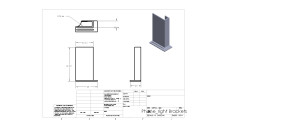
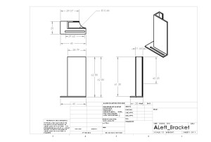
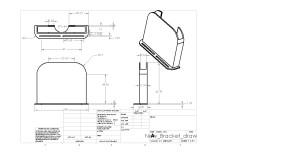
In the last blog post (https://www.arxterra.com/spring-2016-rofi-preliminary-design-documentation/), I designed brackets that support a phone in either vertical or horizontal orientations; therefore, I made a bracket from 2 pieces that can be adjustable to fit with width dimension of the phone. Because my project just needs the phone to be placed in the vertical orientation; therefore, in this new design, I make a one piece bracket for the android phone.

figure7

Drawing diagram

New_Bracket_drawing

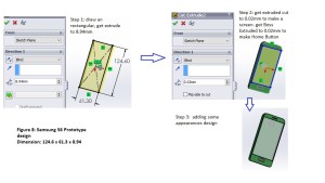
Step 7: Make a prototype of an Android phone

figure8

Step 8: Assembly Modeling and Exploded View

figure9


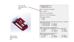
Mass Reports


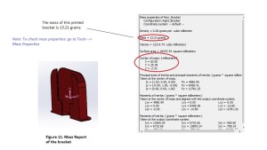
By using the Mass Properties feature, I can determine the mass of the designs before they are printed.

figure11

figure 12

Spring 2016 RoFi: Ultrasonic Sensor Testing

Christopher Andelin (Project Manager)

Mario Ramirez (Systems Engineer)

Qui Du (Manufacturing Engineer)

Andrew Laqui (Electronics and Controls Engineer)

Henry Ruff (Electronics and Controls Engineer)

Testing Ultrasonic Sensor

Andrew Laqui (Electronics and Controls Engineer)

The Ultrasonic Sensor that was on the old RoFia project was the model SEN136B5B. Their testing can be found on this link here, https://www.arxterra.com/ultrasonic-sensor-testing/. Although the RoFia group seemed to have done some quick calculations regarding how far Rofia can detect obstacles, the method of determining these distances are unclear.


For testing, the code found at https://www.arduino.cc/en/Tutorial/Ping was used to test how the sensor worked. Initially, the sensor was not seeming to detect anything, but after double checking the wiring, it was determined that the Fritzing diagram found on the Arduino site had a different wiring than the SEN136B5B sensor. Once the wiring was connected properly, the Arduino serial communication began to immediately print onto the screen. The test code printed the distance that the sensor was detecting, which made it possible to determine what angles the sensor could accurately detect.


A folder was used to simulate a tall object for the SEN136B5B to detect. The folder was held on the side to determine the widest angle the sensor can detect. The sensor was then placed on a tall object in order to determine the vertical detection angles.


The table below has the measurements listed.

table


Spring 2016 RoFi: Preliminary Project Plan

Christopher Andelin (Project Manager)

Mario Ramirez (Systems Engineer)

Qui Du (Manufacturing Engineer)

Andrew Laqui (Electronics and Controls Engineer)

Henry Ruff (Electronics and Controls Engineer)

Table of Contents

Work Breakdown Structure

Christopher Andelin (Project Manager)

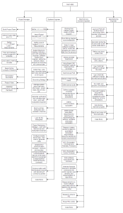
This chart shows the responsibilities of each member. For easier viewing, image can be downloaded by left clicking on the image, then right clicking on the image and finally selecting “Save image as…”

Work Breakdown Structure

Figure 1: Work Breakdown Structure


Project Schedule

This schedule represents the amount of allotted work to be completed and the designated time to complete it.  For easier viewing, image can be downloaded by left clicking on the image, then right clicking on the image and finally selecting “Save image as…”

schedule

Figure 2: Schedule


Burndown and Project Percent Completion

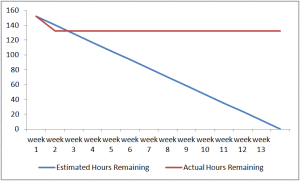
The burndown chart is a visual representation of work completed vs. work that needs to be completed.

burndown chart

Figure 3: Burndown Chart


Project Cost Estimate

RoFi team members will be funding the project and will be reimbursed by the customer (Gary Hill and/or CubeSat and/or the College of Engineering).

This table estimates the costs associated with the RoFi project. As time progresses, our estimated costs will become more accurate.

project cost estimate rev.4

Figure 4: Estimated Cost


System Resource Reports

Mario Ramirez (Systems Engineer)

Figure 5: Mass Report

This current mass report is based on the previous group’s RoFi.  The mass report will be updated as our group updates RoFi.  Expected mass is being gathered from previous stl files.  An issue with SolidWorks is postponing our expected mass results.  Parts labeled, A#, are 3D printed parts and can be referenced below.

image 1

Figure 6: Labeling Parts

image 2

Figure 7: Labeling Parts Continued

power report rev.3

Figure 8: Power Report

Our current power report excludes the android tablet because it has its own power source and it is not being powered by RoFi’s on board power supply.  For Servos, I have decided to include the stalled current in this report because it is the max current the servos will draw and we must be able to provide enough power for any situation that RoFi encounters.  The power report will be updated weekly based on the updates we provide for RoFi.

Spring 2016 RoFi: Preliminary Design Documentation

Christopher Andelin (Project Manager)

Mario Ramirez (Systems Engineer)

Qui Du (Manufacturing Engineer)

Andrew Laqui (Electronics and Controls Engineer)

Henry Ruff (Electronics and Controls Engineer)


Table of Contents

Program Objectives

The objective of Project RoFi’s is to design and implement a compact biped robot based on the original RoFi design by Jonathan Dowdall as described on the Project Biped website and quoted here.

ROFI is the fifth prototype from Project Biped.  It is a self-contained, bipedal robot that uses accelerometer feedback to balance. It has 12 DOF (degrees of freedom) and can walk around while avoiding obstacles using an ultrasonic range sensor. A small Android tablet in ROFI’s head provides the brains and an Arduino Mega provides the hardware interface.

All CSULB versions of RoFi add telerobotic control (including navigation) and monitoring of the robotic system by incorporating the Arxterra application and control panel.

The initial objective for the Spring 2016 project is to make operational the RoFi (Fifth Generation Robot), which was built during the Fall 2014 semester, as defined in the “BiPed Final Documentation.” The major change made in the Fall 2014 version of RoFi from the original, was to upgrade the head assembly to include a rotating mirror allowing the robot to view its surroundings.

Once operational this RoFi will run the course defined in the Mission Profile to the best of its abilities.  The Spring 2016 version of RoFi will identify and correct any design problems identified during this test.

The major change to be incorporated into the 2016 semester’s RoFi is the replacement of the overlarge head with a more compact design. Identified changes include:

  • Remove pan and tilt mirror assemble. While an Android or iPhone is still a requirement, vision may be provided by a commercially available periscope lens subassembly.
  • Replace the Arduino Mega with an Arduino with a much smaller form factor.
  • Replace the fuse and switch with more compact designs.
  • Replace the polyfuse array with an SMT equivalent design.
  • Replace all PCBs with custom designed SMT solutions.

Finally, the design will correct problems identified as part of the creativity exercise as documented in Creativity Section of the “Spring 2016 RoFi: Research Projects and Creative Exercise.” These include…

  • Bolts screwed into a plastic frame, which can come loose over time.
  • A running time of only 10 to 15 minutes.
  • Cables that are exposed and can easily come loose.
  • Moving parts that can cause harm.

Mission Profile

RoFi must complete an obstacle course on a figure 8 track. The course, shown in Figure 1, and located in VEC-501 was designed to validate RoFi’s design. The course will test RoFi’s ability to navigate in different directions and inclinations, over different surfaces, while keeping its balance.
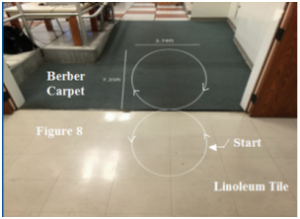
track

Figure 1 The VEC-501 Course

As shown in Figure 2, the obstacle course will require RoFi to cross over a threshold, at approximately a 45° angle and a 2 cm height. From there RoFi must ascend an incline that is initially an 8° slope which then decreases to a 6° slope. Half way through the course RoFi must then start its descent down the incline towards the threshold again crossing over it at about a 45° angle proceeding towards its start position. Additionally, RoFi must acknowledge and avoid an object (i.e. a wall) and be able to traverse multiple types of surfaces which will include carpet, linoleum tile, and metal as defined here.  All of this must be completed while using the Arxterra™ application as per requirements.
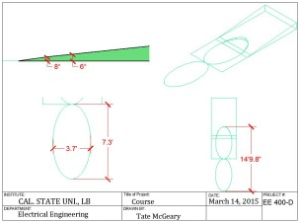
slope

Figure 2 Course Details

*The above diagram was created in AUTOCAD™ 2014.

*Measurements were provided by the microSegway group, and confirmed by the microBiPed group as documented in the Micro BiPed Introduction.

Requirements

Program/Project

  1. Modifications to RoFi shall not exceed $320
  2. RoFi shall acknowledge and avoid objects within 3 feet
  3. RoFi shall traverse carpet, linoleum tile, and metal surfaces
  4. RoFi’s runtime shall be greater than 15 minutes
  5. RoFi shall cross over a threshold, at approximately a 45° angle and a height of 2 cm
  6. RoFi shall ascend an incline that is initially an 8° slope which then decreases to a 6° slope
  7. RoFi shall complete the figure 8 obstacle course through the Arxterra Application during finals week (Monday, May 9 – Saturday, May 14, 2016)
  8. Vision shall be provided through the onboard phone

Source: https://www.arxterra.com/fall-2015-microbiped-preliminary-design-documentaion/


Requirements (System/Subsystem)

Mario Ramirez (Systems Engineer)

  1. To satisfy requirement 1.5 and 1.6, RoFi shall use a gyroscope sensor to walk up an incline of up to 45 degrees.

a. A gyroscope sensor detects change in circular motion and orientation. Therefore a gyroscope sensor can be used for sensing: angular velocity, angle, and motion.  Such sensors are used in items such as cameras, aircrafts, and space shuttles.  This will therefore allow RoFi to adapt to inclines and accomplish requirement 1.7.

b. Our value of 45 degrees was obtained from the angle of the threshold within the obstacle course.

http://www5.epsondevice.com/en/information/technical_info/gyro/

  1. To satisfy requirement 1.2, RoFi shall use an ultrasonic sensor with a range of 3cm to 400cm.

a. An ultrasonic sensor emits sounds waves and are received back after reflecting off an object or surface. This type of sensor works on metal, nonmetal, clear, liquid, or solid materials.  The received waves can calculate the distance from an object using echolocation similar to that of a bat. The previous semester’s ultrasonic sensor has a range of 3-400 cm.  Other sensors have a range of 3-400cm. Our software will determine the range at which RoFi will avoid an obstacle.  This distance will be determined once the head design is complete and we know the height placement for the sensor. An ultrasonic sensor will allow RoFi to detect and avoid objects even in the dark within an optimal range.

b. The optimal distance for RoFi to begin his avoidance maneuver will be tested.

http://www.ab.com/en/epub/catalogs/12772/6543185/12041221/12041229/print.html

https://www.teachengineering.org/view_lesson.php?url=collection/umo_/lessons/umo_sensorswork/umo_sensorswork_lesson06.xml

http://www.seeedstudio.com/wiki/Ultra_Sonic_range_measurement_module#Introduction


  1. To satisfy requirement 1.3, RoFi shall have material with a coefficient of friction on the bottom of his feet.      

a. The material that RoFi will have on his feet will be based on our research of what material allows RoFi to walk on multiple surfaces, but still be able to move freely.


  1. To satisfy requirement 1.4, RoFi shall use two Glacier 2600mAh 2S 7.4V LiPo Receiver Batteries

a. More information is found here https://www.arxterra.com/spring-2016-rofi-battery-trade-off-study/

  1. To satisfy requirement 1.7, RoFi shall use a power class 2 Bluetooth module, which has a range of 10 meters between the module and cell phone.

a. Bluetooth operates in a band of 2.4 to 2.485GHz. A Bluetooth module will allow for communication between a cellphone and our Arduino.  From here we can use the ArxRobot app in order to control our Arduino which is ultimately controlling our robot.

https://learn.sparkfun.com/tutorials/bluetooth-basics/how-bluetooth-works

  1. To satisfy requirement 1.7, RoFi shall use servos that can supply a minimum torque of 288 kg*cm.      

a. To insure that RoFi can walk the torque stated above is needed to move the largest mass attached to our servos. To calculate this torque we used torque=r*F*sin(theta).  Where r is the distance and F is F=mass*gravity.

Link to the finalized torque report will be provided soon.

  1. To satisfy requirement 1.1, We shall:

a. Use 11 out of 12 servos from the previous group, one is broken and must be replaced.

b. Test sensors and use all operational components.

c. Re-use wires.

d. Allocate most budget resources to updating the Arduino and parts needed to implement our design on a smaller Arduino. These parts are referring to components such as servo drivers.

      8. To satisfy requirement 1.8, We shall be implementing a parascope that attaches to the onboard phone

a. TBD


Product Breakdown Structure
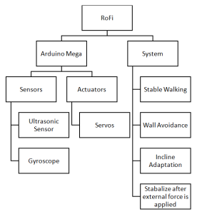
pbs

System Block Diagram

Adapted from,  https://www.arxterra.com/fall-2015-microbiped-system-block-diagram-update/
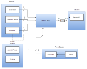
system block diagram

The sensors subsystem will be in charge of telling RoFi his next action.  When the gyroscope senses an incline/decline this will alert the Arduino which ultimately leads to the Actuators subsystem to adapt accordingly based on our code.  The same process will occur when the Ultrasonic sensor senses an object or a wall ahead of RoFi.  Bluetooth is considered a sensor because it collects inputs from a source, in this case an Android phone, then sends that data to the Arduino thus telling RoFi what to do based on our code.  The communication subsystem is connected to the sensors subsystem because through Bluetooth the Arduino will obtain information on the action it will take.  The Power subsystem consists of the battery which has been tested for our overall system and a regulator to insure the safety of the system and the user(s).  Our Actuator subsystem is our output, RoFi’s desired movement, based on our sensors and code

Interface Definitions

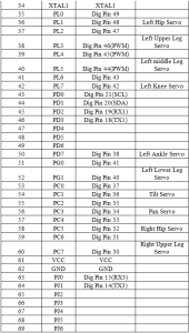
https://www.arduino.cc/en/Hacking/PinMapping2560

https://www.arxterra.com/project-documentation/
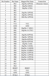
table1

table2

table3

arduino mega

Taken from, https://www.arxterra.com/project-documentation/
This Eagle schematic shows direct connections from the sensors and actuators to the Arduino Mega.


Mechanical Design

Qui Du (Manufacturing Engineer)

Objectives for this Design

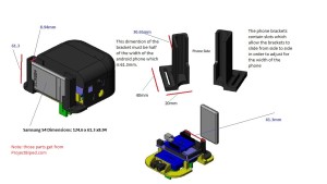
The Android device is attached to RoFi’s head to control the Aduino Mega board. A phone with dimensions 124.6 X 61.3 X 8.94 is used for this project. As Manufacturing Engineer, I need to design phone brackets that will attach to the android phone on RoFi’s head. After doing research on this topic, I have ended up with the “RoFi- Next Generation Head- DAREL” designed  by Mike Pluma. I used the phone brackets prototype from this design to remodel brackets using SolidWorks that could fit with our android device dimensions.

SolidWorks 3D Modeling Design

The phone brackets attach to the back of the body base of RoFi. The screws go through the slots on the brackets and the holes in the body base. In this design, the bracket will support the phone in either verital or horizontal orientation. To achieve this goal, I design the width of  each bracket to have the dimensions of half the phone’s width.

Width dimension of bracket=(width dimension of phone)/2 = 61.3/2= 30.65mm

Brackets Dimension Analysis Model (Printed parts from RoFi Project)

Source: http://web.csulb.edu/~hill/ee400d/Project%20Folder/Robots%20and%20Drones/BiPed%20Robot/RoFi%20Project/
Bracket Dimension Model

SolidWorks Brackets Design

Step 1: SolidWorks model of right bracket:
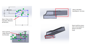
Right Bracket design

Drawing modeling of right bracket:

Drawing_Right_Bracket

Step 2: SolidWorks model of left bracket:
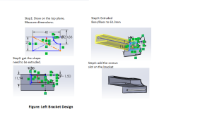
left bracket design

Drawing Model of left bracket

Drawing_Left_Bracket

Step 3: SolidWorks model of the Android device

Phone’s dimensions: 124.6 x 61.3 x 8.94mm
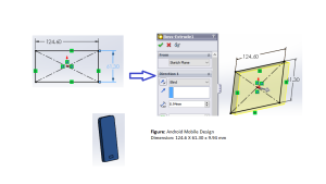
Android Mobile figure

Step 4: Assembly modeling and exploded view

The high sides of the brackets support the phone in the vertical orientation
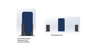
Exploded View_Vertical

Phone_Brackets_Vertical_Assembly

The high sides of the brackets support the phone in the horizontal orientation
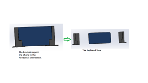
Exploded View_Horizontal

Phone_Brackets_Horizontal_Assembly


Electronic System Design

Subsystem Descriptions

Henry Ruff (Electronics and Controls Engineer)


Servos:

The core part of ROFI utilizes 12 servos working together to create bipedal movement. Each of the servos will be controlled by appropriate code, to construct frame-by-frame animation of ROFI walking.


Gyroscope Testing:

In order to utilize the gyroscope for stabilization purposes, experiments will be conducted to read sample data from a force being applied, and then coding the servos to respond appropriately in order to correct ROFI’s center of balance, allowing him to recover from the force that was applied to him.


Ultrasonic Sensor:

The ultrasonic sensor will be appropriately tested to be able to have the servos respond in a way that allows for suitable avoidance of objects.


Power Consumption:

Applicable to all electronic aspects of the project, it is essential to the project to know the overall expected power consumption of ROFI. In this case, each component’s rated specifications can be used to calculate their power consumption, and altogether an estimate can be made for ROFI. Listed below are the maximum power consumption of each component, their datasheets, and the expected total.

As for the Arduino Mega in particular, the amount of current it draws is dependent on the amount of pins used, the code being run, and components of the Arduino board itself. Because of this, its power consumption will be measured once fully assembled.
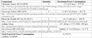
table rev.2


Fritzing Diagram

Andrew Laqui (Electronics and Controls Engineer)

Fritzing Diagram:
The diagram shows a simple way of wiring the Arduino MEGA, Bluetooth communicator, accelerometer, and servos together using a breadboard and power supply. This is the beginning of how we will design our group’s PCB.
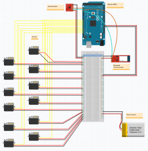
Fritzing Diagram

Fritzing Schematic:
The schematic is a more detailed depiction of how the parts will be wired together. The schematic shows on the Arduino MEGA which pins will be used. As seen in the schematic, all twelve PWM pins will be used for the twelve servos that are predicted to be used for RoFi.
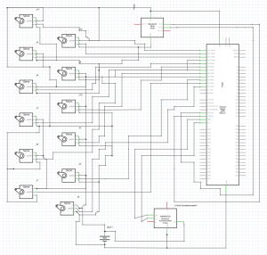
Fritzing Schematic


Spring 2016 RoFi: Research Projects and Creative Exercise

Christopher Andelin (Project Manager)

Mario Ramirez (Systems Engineer)

Qui Du (Manufacturing Engineer)

Andrew Laqui (Electronics and Controls Engineer)

Henry Ruff (Electronics and Controls Engineer)

Table of Contents

Project Manager Research

Christopher Andelin (Project Manager)

Source Material

  1. Project Biped, Overview; http://www.projectbiped.com/prototypes/rofi
  2. Micro BiPed Introduction, Mission Objective and Mission Profile; http://arxterra.com/micro-biped-intoduction/
  3. Micro BiPed Requirements; http://arxterra.com/requirements/
  4. Micro BiPed Requirements Level 1 and 2, Cost, and Schedule; https://www.arxterra.com/final-documentation-microbiped/
  5. The Engineering Method; http://web.csulb.edu/~hill/ee400d/Lectures/Week%2002%20Engineering%20Method/b_Engineering%20Method.pdf
  6. Mission Profile and Project Objective; https://www.arxterra.com/fall-2015-microbiped-redefining-mission-objective/
  7. Mission Objective, Mission Profile, Level 1 and Level 2 Requirements, Cost, Schedule; https://www.arxterra.com/wp-content/uploads/2015/05/Spring-2015-%C2%B5BiPed-Perliminary-Design-Document.pdf

Mission Objective and Mission Profile

The Project Objective and Mission Profile is a statements of a problem to be solved.  If along the way the customer changes their minds it is okay to let the customer know that the change is out of scope and there may be an increase in cost of schedule slip.  The Mission Profile confirms that the Engineers design solves the customers’ problem through validation tests.

The Spring 2015 Mission Object biped project does not state a problem to be solved instead explains that the goal is to shrink the design to a micro biped.  The Mission Profile comprises of validation tests that are specific and appear feasible due to the design of the micro biped.

Level 1 program/ project requirements

The requirements of Spring 2015 biped project done correctly

  • requirements are quantitative, verifiable and realizable
  • provided source material
  • moves the design process forward
  • located at the correct level (1- program/project)
  • requirements are separated

Done incorrectly

  • used the word must instead of shall
  • no equations

Costs

  • The predicted cost of Spring’s 2015 biped project was $395.15 and the actual total cost was $277.13 (source 4)
  • Our Preliminary budget is $300.00

Scheduling

The Spring 2015 biped team spent a lot of time on planning, reviewing code, selecting a microcontroller, manufacturing, software and testing. It is advised to prepare for unforeseen circumstances (source 4).


Systems Engineer Research

Mario Ramirez (Systems Engineer)

Source Material

1.”Project Biped”, 1/31/2016 http://www.projectbiped.com/prototypes/rofi

2.”Fall 2015 microBiPed Summary”,BiPed, Page 1, 1/31/2016 https://www.arxterra.com/fall-2015-microbiped-summary/

3.” Fall 2015 MicroBiPed Verification and Validation Tests”, BiPed, Page 1, 2/1/2016 https://www.arxterra.com/wp-content/uploads/2015/12/Test-Plans-for-Verification-and-Validation.pdf

4.” Fall 2015 MicroBiPed Center of Mass”, BiPed, Page 1,2/1/2016  https://www.arxterra.com/fall-2015-microbiped-center-of-mass/

5.” Fall 2015 MicroBiPed Stress Analysis”, BiPed, Page1,2/1/2015 https://www.arxterra.com/fall-2015-microbiped-stress-analysis/

6.” Fall 2015 MicroBiPed Wiring Diagram”, BiPed, Page  ,2/1/2016 https://www.arxterra.com/fall-2015-microbiped-wiring-diagram/

7.” Fall 2015 MicroBiPed Center of Mass”, BiPed, Page  ,2/1/2016 https://www.arxterra.com/fall-2015-microbiped-center-of-mass/

  1. “Fall 2015 MicroBiPed Preliminary Project Plan”, Biped Page , 2/8/2016 https://www.arxterra.com/fall-2015-microbiped-preliminary-project-plan/#Requirements_Verification_Level_1_8211_Program_Requirements


RoFi is a two legged BiPed robot designed by Jonathan Dowdall.  RoFi should be able to walk on only two feet without falling over, avoid walls as well as other objects.  RoFi should be able to do these operations by communicating with the Arxterra app.

As the system engineer of the RoFi project group I am in charge of assisting with level 2 requirements, the cable tree, box diagrams, intangibles, testing, and verification/validation.  Reviewing Jonathan Dowdall’s website and the BiPed section on the Arxterra blog I have come up with a review of RoFi.
Level 1 requirements for RoFi consist of maintaining balance, be able to detect and adapt to incline or declines, avoid walls and objects using an ultrasonic sensor, and be able to communicate with the Arxterra app.  Most of requirements posted by previous teams were for a microBiPed.  Since we are working with an original size BiPed the level 1 dimension requirements do not apply to us and were omitted.  All these requirements are qualitative in my perspective because they give exact detail on what RoFi must be able to do and also lead to a design and further level 2 requirements.

Level 2 requirements for RoFi specify what is going to be designed in order to achieve the level 1 requirements.  For the level 1 requirement of avoiding walls to be met the level 2 requirement should state what sensor is being used and the reasoning behind it.  Some previous groups state using a ultrasonic range sensor and other groups do not state the sensor at all in their requirements.  For our level 2 requirements to lead to a proper design I think we need to state what sensor we will be using and why we chose that sensor.  Another level 2 requirement obtained from the blogs will be the use of a gyroscope to sense the incline or decline of the surface.  However, some research has lead me to believe that the gyroscope is not the most effective sensor.  Testing an accelerometer and comparing it to a gyroscope might lead to possible solutions.  Other level 2 requirements consist of: usage of Arduino Mega, Bluetooth used to communicate with Arxterra app, and grip pad on the soles of RoFI.  These requirements meet a qualitative and quantitative criteria in order to push the design of the project forward.

Validation/verification go hand in hand with requirements because the validation form goes through the requirements and states if and how those requirements were met.  I think previous teams did a good job with their validation form because I was clearly able to understand what requirements were easy to meet, which were more difficult, and which requirements were not able to be met.

Tests done for the BiPed robots consist of power distribution testing, servo torque testing, limb strain testing, and center of mass testing.  The blogs from previous teams state clearly the experiment they did and the results achieved.  However, not much detail in the process of how the experiment was always given.  I think enough detail should be given so the next engineer could redo the experiment if needed.  I also believe more testing on the ultrasonic sensor should be done.  Previous teams have testing on the connections of the sensor, but I did not see testing on the range of the sensor or if any objects cannot be distinguished by the sensor.

Intangibles are an important task for the systems, missions and tests division of any project.  I read some intangibles within tests of previous teams, but for clarity and future teams I believe a structured table would be beneficial so it is clear what teams in the future need to test for their design.


Electronics and Controls Engineer Research

Andrew Laqui (Electronics and Controls Engineer)

Source Material

https://www.arxterra.com/microsegbot-fall-15-final-document/

https://www.arxterra.com/spring-2016-velociraptor-roles-responsibilities/

  1. MicroSegbot Fall 15′ Final Document, Level 2 Requirements #7, February 2, 2016 https://www.arxterra.com/microsegbot-fall-15-final-document/
  2. MicroSegbot Fall 15′ Final Document, Bluetooth Trade-Off Study, February 2, 2016 http://arxterra.com/bluetooth-trade-off-study/
  3. MicroSegbot Fall 15′ Final Document, Microcontroller Trade-Off Study, February 2, 2016 http://arxterra.com/microcontroller-trade-off-study/
  4. Final Documentation MicroBiPed, Requirements level 1 and 2, Level 2 Requirements #1, February 10, 2016 http://arxterra.com/requirements/
  5. Final Documentation MicroBiPed, Requirements level 1 and 2, Level 2 Requirements #9, February 10, 2016 http://arxterra.com/requirements/

The level 2 requirement #7 from the MicroSegbot project from Fall 2015 stated that the robot must utilize a microcontroller that will support each component that is used in accomplishing the program requirements.

  • This requirement was not quantitative, but it was verifiable and realizable. The nature of this requirement was that it could not be quantitative. This requirement was a direct response to the level 1 requirement that stated, “The MicroSegbot will use an android phone/laptop to navigate wirelessly by the customer.” This requirement was appropriately a level 2 requirement because it was a requirement that would directly cover a level 1 requirement. There were no links in the document for this requirement other than a link to the beginning of the design document. This requirement moved the design process forward because it determined how the robot was controlled. There were no equations in this requirement. The language was not in the form of a requirement; the author did not use the word “shall” nor the word “should”.


The Bluetooth Trade-Off Study from the MicroSegbot project from Fall 2015 considered the level 2 design requirement #3. The author stated that Bluetooth communication was required because the robot was to be controlled by an android phone.

  • The trade-off study is quantitative because it speaks to the specific values for the specifications of two different Bluetooth devices. The study did not seem to contain any non-essential information. The study clearly expressed why the preferred device was chosen.


The Microcontroller Trade-Off Study from the MicroSegbot project from Fall 2015 considered the level 2 design requirement #7.

  • The study was quantitative because it compared 3 different devices based on different numerical values. The study does not contain any non-essential material. It compares nine different specifications that are all relevant to deciding which microcontroller would be preferred.


The level 2 requirement #1 from the μBiPed project from spring 2015 stated that the robot will utilize an HC-SR04™ ultrasonic sensor. The reason for this sensor is that it is less susceptible to noise and cost.

  • The requirement was not quantitative, but it was verifiable and realizable. The nature of this requirement is that it cannot be quantitative. It is located in the correct level because it clearly stated which level 1 requirement it was linked to. The requirement also contains a link that goes to the sensor study. This requirement moves the design process forward because the customer specifically wanted the robot to avoid obstacles, and this sensor will allow the robot to do that. No equations are used. The author should use the word ‘shall’ rather than ‘will’ in order to use the proper language for a requirement.


The level 2 requirement #9 from the μBiPed project from spring 2015 stated that a Bluetooth IC will be chosen to communicate with the Arxterra™ program. An IC must be used in order to minimize the μBiPed size and mass. The type of Bluetooth IC is HC-06.

  • The requirement was not quantitative, but it was verifiable and realizable. The nature of this requirement is that it also cannot be quantitative. It is located on the correct level, and it clearly stated which level 1 requirement it was linked to. The requirement does not contain any links to any source material. It could use a link to the specs for the IC or a link to a trade-off study as to why that IC was chosen. This requirement moves the design process forward because the customer wanted the robot to be able to be controlled remotely using the Arxterra™ program. No equations were used. The author should use the word ‘shall’ rather than ‘will’ in order to use the proper language for a requirement.


Manufacturing Engineer Research

Qui Du (Manufacturing Engineer)

Objective:

As a Manufacturing Engineer, I will be responsible for the PCB layout and assembly. My job is using the Eagle CAD programing to design the PCB (printed circuit board), perform ERC (electrical rule check) and DRC (design rule check), and generate the CAM file and upload to PCB house for fabrication. Beside of this, I also will be responsible for 3D modeling to design all Rofi printed parts by using Solidworks.

Source Materials:

  1. Barajas, Alejandro (Fall 2014).”Biped Final Documentation.” Arxterra Blog Post https://www.arxterra.com/final-documentation/
  2. Geijtenbeek, Thomas. “Flexible Muscle-Based Locomotion for Bipedal Creatures.” YouTube. https://www.youtube.com/watch?v=pgaEE27nsQw
  3. Kiley, Steven. “SolidWorks Intro Tutorial.” YouTube. YouTube, n.d. Web. 11 Feb. 2016.

https://www.youtube.com/watch?v=TvBoZ6kH3Q8

  1. Balagtas, Michael (Fall 2015).”MicroBiPed PCB.” Arxterra Blog Post

https://www.arxterra.com/fall-2015-microbiped-pcb/

  1. Blum, Jeremy. “Tutorial 1 for Eagle: Schematic Design.” YouTube

https://www.youtube.com/watch?v=1AXwjZoyNno

REVIEW OF MATERIALS:

  1. This blog is well organize and useful. I really love the “Ideas and advice for future classes” section because the biped project is hard project that maybe not be done in semesters or even years; It is helpful if a previous semester student document all of the obstacles and suggestions for future semester student to review. From this blog, I learn that getting a prototype for a Rofi before getting parts 3D-printed is very important because prototypes allow the team to see any probable design conflicts that can be corrected before final 3D-prints. This technique could save a lot of money and time. The other great advice that I learn from this blog is try to make a physical layout of how I imagine the board to look. Because even the PCB layout was designed correctly and functionality; in some circumstance, It might not match with pins of components which needed to attached to PCB layout. This issue might take a team a lot of time to solve or even lead the team to redesign a PCB layout; therefore, it is important to make a physical layout of how we imagine the board to look.
  2. As a manufacturing engineering, my main job is to design 3D modeling of a Biped on Solidworks; It is useful for me to visualize the flexible Muscle-Based locomotion for Bipedal creatures. From above video, it shows a control 3D muscle actuation of a biped which helps me to realize that the different dimension of a biped will lead to different types of movement so that I can choose the dimension type of my biped.

This video also shows how to optimize for different target speeds (different dimension of a biped have different target speeds). For example, for a too wide Bipet, we will be faced with an issue of low speed; however, for this type of biped, we will take an advantage of avoiding the biped to fall sideway. In contrast with a too wide Biped, a too tall Biped could achieve a high target speed, but it has an issue with being easy to fall down to all direction. From this information, I realize that the outfit of a biped is very important consideration to design a good Biped which could match with requirement of balancing and achieve a target speed. In other words, in order to design a desirable target speed biped, I really need to design the right outfit for the Biped.

  1. To get ready to handle my jobs position, I do self-training my 3D modeling by watching above training video. This video is well organize, and easy to follow step by step. It helps me to be familiar with Solidworks and future designing of printed parts for the Rofi such as: foot, servo band, servo wrap, or knee frame.
  2. From above blog, the manufacturing engineer had a problem with a free version of EAGLE since it has a limit of 2in x 2 1⁄2in; therefore he/ she did not have the liberty of space to maneuver around the conflicted part. If I am in this situation, I suggest he/ she tries to use a license version of EAGLE from school or try to reorganize the wires and components to make them more space less.
  3. As important as 3D modeling, Eagle CAD is software that I use to build the PCB layout. To get handy with this tool, I also watched some of training tutorials online and followed the instructions to repeat rebuilding it. By following the tutorial, here is a final result.


Electronics and Controls Engineer Research

Henry Ruff (Electronics and Controls Engineer)

Source Material

Project Biped

Jonathan Dowdall

  1. ROFI – Project Biped, 2/3/2016, http://www.projectbiped.com/prototypes/rofi
  2. Progress Setbacks, 11/7/2011, http://www.projectbiped.com/updates/blog/progressandasetback
  3. ROTH post mortem, 1/11/2012, http://www.projectbiped.com/updates/blog/rothpostmortem
  4. ROFI parts list, 2/3/2016, https://docs.google.com/spreadsheets/d/1PdzezPRsNnxsz-CfU83IURZGI23ftaexhAVR2sCV_Vs/edit#gid=0

Arxterra

  1. Requirements, 2/8/2016, https://www.arxterra.com/requirements/
  2. Fall 2015 MicroBiped Motion Sensor, 12/7/2015, https://www.arxterra.com/fall-2015-microbiped-motion-sensor/
  3. Fall 2015 MicroBiped Distance Sensor, 11/2/2015, https://www.arxterra.com/fall-2015-microbiped-battery-update/
  4. Fall 2015 MicroBiped Microcontroller, 11/3/2015, https://www.arxterra.com/fall-2015-microbiped-microcontroller/
  5. Fall 2015 MicroBiped Servo, 10/23/2015, https://www.arxterra.com/fall-2015-microbiped-servo/


Review of Literature

Project Biped – This documentation on projects ROFI and ROTH provides insight on design complications and specifications necessary for the requirements of building a bipedal robot. These studies elaborated on level-2 design requirements, with each portion working towards furthering the overall design. For more detailed specifications, the ROFI parts list provides exact components used previously, and this is a useful reference point. The ROFI website itself is a more direct resource as compared to the Arxterra posts, as the latter is not specifically for ROFI itself.


Arxterra – The Arxterra blog posts presented insight on component options and testing performed by previous, comparable biped projects. Furthermore, they outlined requirements for biped projects that can similarly be applied to the ROFI robot.


Requirements – A compilation of understanding of the previous articles, as well as observations and personal commentary on necessary adjustments or changes to the project overall.

  • Autonomous bipedal walking
    • Balanced during each frame of walking movement
      • Fast movement would keep balance, such as with human walking, but this is unfeasible for this project. Instead, slow movement would necessitate being able to have a center of gravity that is balanced during each frame of movement.
    • High torque servos
      • Microcontroller to handle servos
      • Servos cannot be utilized constantly due to risk of overheating
      • Servos should withstand weight of overall project
        • Servo strength/torque can be determined by physics calculations or modeling experimentation
        • If the overall weight can be reduced, then lighter servos can also potentially be used.
      • Able to handle sloped surfaces as well as varying textured surfaces
        • Gyroscope and accelerometer are viable for feedback that can be read and therefore controlled, to be able to make ROFI react in a way that will allow it to balance. Accelerometer is better able to handle inclines, as explained in the source material above.
        • Grip exists on the soles of ROFI’s feet, allowing it to be able to walk on feasible surfaces. Its movement also should raise each foot a high enough distance while remaining flat, to be able to avoid complications that would occur if its feet moved very close to the ground.
      • Pathfinding around obstacles
        • Can utilize ultrasonic or infrared sensors to determine distance and appropriate response, such as stopping at a gap or turning at a wall.
        • Needs a method of turning through bipedal motion
          • Design can be modified or servos used in a way that creates rotational torque to turn the body while still keeping balance
        • Obstacles include objects in the way as well as terrain differences
      • Controlled by Arduino board, with interaction with a mobile phone app.
        • As ROFI is autonomous, the main app interaction will be to turn it on or off.
      • Stabilization if disturbed by an external force from any angle, at any point of ROFI, and at any strength.
        • Accelerometer can be used to be read by ROFI, and then it will perform an appropriate equal force in the opposite direction to be able to balance itself.
        • A force too strong will not allow for ROFI to respond quick enough to balance, so there must be a determined limit as to what ROFI can feasibly respond to.


Creativity Exercise

Christopher Andelin (Project Manager)

Mario Ramirez (Systems Engineer)

Qui Du (Manufacturing Engineer)

Andrew Laqui (Electronics and Controls Engineer)

Henry Ruff (Electronics and Controls Engineer)

Problems

  1. The bolts screw directly into the plastic frame causing the bolts to come loose.
  2. Running time is 10 to 15 minutes.
  3. Cables are loose and exposed.
  4. Moving parts can cause harm.

Brainstorming Solutions

  1. Retrofit the broken frame by using SolidWorks 3D modeling.
  2. Screw hardware into rigid material instead of the plastic frame.
  3. Redesign current material by making it lighter ( less power consumption, help the battery last longer)
  4. Use lighter material for Rofi, for example: wood, aluminum, cardboard paper.
  5. Use shorter cables, reroute, and/or use enclosure
  6. Design a material that can be placed around RoFi’s legs in order to cover the moving parts and cables. Pants with pockets can hold various objects.

Lateral Thinking

Forced Relationship:

  1. Cheerios – Honey comb pattern for printed limbs.  This will reduce weight since less material will be used.  However, stress tests would need to be done in order to verify the new design could handle RoFi’s movement.
  2. Volleyball – Use as a protective layer to protect internal components and protect user.  
  3. Baby – Rofi can act as a baby monitor. It will follow the baby around, and if the baby cries, Rofi will notify the parent via cell phone.

Different Point of View

  1. Rofi – “What kind of accessories can I have?”
    • Reprogram RoFi to allow one leg remain bent when attached to a skateboard while the other leg kicks and pushes.
    • RoFi can have an assortment of outfits to customize the appearance.
      1. Dress/Wig
      2. Army Uniform
  2. Customer – “How else can I use RoFi other than just for a toy?
    • Program alarm clock to the phone. When the alarm goes off in the morning, RoFi will walk away, forcing the customer to catch up to RoFi and turn off the alarm.

Experiments

  1. Stress test for frame and hardware.
  2. Test the flexibility of the volleyball  material
  3. Verify that changes do not impede movement
  4. Overall heat of the system needs to be tested to insure that the added material will not cause RoFi’s components to overheat.

Questions

  1. Is there a way to lower costs?
  2. Will shorter cables impede movement?
  3. How will the phone be attached?
  4. Can we remove any unnecessary parts?
  5. Should we color code the wires?
  6. Can we salvage PCB parts?
  7. Can we use a smaller Arduino?
  8. Can we upgrade the power supplies?
  9. Are there any maintenance that needs to be performed?
  10. Does RoFi need to be stored in a particular environment?