Spring 2016 RoFi: Verification Test Plan

Christopher Andelin (Project Manager)

Mario Ramirez (Systems Engineer)

Qui Du (Manufacturing Engineer)

Andrew Laqui (Electronics and Controls Engineer)

Henry Ruff (Electronics and Controls Engineer)

Table of Contents

Verification Test Plan

Mario Ramirez (Systems Engineer)

Purpose

To verify requirements based on the verification matrix.

Requirements

  • RoFi shall remain balanced over an inclined surface of  up to 8 degrees and a threshold of up to 45 degrees.
  • The ultrasonics sensor shall detect an object within 3-400cm and begin an avoid obstacle subroutine.
  • Nonslip material, on the bottom of RoFi’s feet, shall have a friction coefficient greater than 0.9.
  • The Bluetooth module shall be a power class 2 Bluetooth module which gives a range of 10 feet between the module and the cell phone.
  • Servos shall supply a minimum torque of 288kg*cm to move a mass of 862g.
  • The periscope attached to the cell phone shall have a lens size of 1.8 * 1.8 * 2.2cm and give a 90 degree view from the cell phone camera.

Matrix

Figure 1A and Figure 1B is the verification matrix.

figure 1a

Figure 1A: Verification Matrix

figure 1b

Figure 1B: Verification Matrix

Tests

Incline

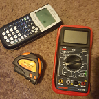
Figure 2 is a table of the tools needed for determining the angle of an inclined surface.

figure 2

Figure 2: Tools used for Incline

To conduct this test, I can either locate surfaces at varying angles or I can construct a ramp and put things underneath to adjust the angle from 0 to 30 degrees.

Steps:

  1. Measure angle of desired surface.
  2. Command RoFi to walk up the surface.
  3. Gather information from the Arduino IDE serial Monitor and compare to measured results.

Detection

Figure 3 is a table of the tools needed for testing the ultrasonic sensor.

figure 3

Figure 3: Tools used for Ultrasonic Sensor

The measuring tape will be used to verify that the results the serial monitor is displaying is accurate and that the sensor can detect objects within its given range.

Steps:

  1. Setup ultrasonic sensor circuit and code.
  2. Place the measuring tape alongside the ultrasonic sensor.
  3. Starting at about 400 cm away from the ultrasonic sensor, move an object at 5 cm increments.
  4. As object is moved, compare the serial monitor and the measured values.

Feet Material

Figure 4 is a table of the tools needed for calculating the friction coefficient of RoFi’s shoes.

figure 4

Figure 4: Tools used for Calculating Friction Coefficient

Equation:

  1. Ff = force of friction
  2. μ = friction coefficient
  3. F f = μ *m *g *c o s( α)

Steps:

  1. Place material that is to be measured on an adjustable ramp.
  2. Place mass on the material to be measured and angle the ramp until it begins to slide down the ramp.
  3. Calculate the force needed to move this material down the slope.
  4. Verify that the force of RoFi’s step is less than the force needed to make the material slip.

Bluetooth Module

Figure 5 is a table of the tools needed for testing the Bluetooth module.

figure 5

Figure 5: Tools used for Testing Bluetooth

Setup the Bluetooth module with the Arduino and a simple LED for testing.  Insure your code is uploaded to the Arduino and begin.

Steps:

  1. Lay out the measuring tape to read between 1 to 10 feet.
  2. Starting from 1 foot, turn the LED on and off to insure you are connected.
  3. Move away 0.5 feet and again turn the LED on and off to insure you are connected.
  4. Repeat step 3 until you reach 10 feet.

Servos

Figure 6 is a table of the tools needed for testing the servo torque.

figure 6

Figure 6: Tools used for Testing Servo Torque

https://www.arxterra.com/spring-2016-rofi-torque-report/

Weigh out a mass of 900g,  we are using 900 grams because it is easier to obtain this value and if the servo can move 900g it can move 862g.  Connect a resistor of 1 ohm or less in series to the ground of the servo.  Connect the oscilloscope to measure the voltage over the resistor. Use V/R=I to obtain the current the servo is drawing.

Steps:

  1. Mount the servo on the edge of a table.
  2. Connect the mass to the servo with twine or rope.
  3. As the mass is moving, calculate your current drawn to insure that it is below your stalling current.

Periscope

To verify that the periscope provides a 90 degree view relative to the camera.

Figure 7: Tools used for Testing Periscope

Steps:

  1. Attach periscope to the cellphone camera.
  2. Take photos and/or video.
  3. Connect to Arxterra control panel and verify vision.

Spring 2016 RoFi: Debriefing

Christopher Andelin (Project Manager)

Mario Ramirez (Systems Engineer)

Qui Du (Manufacturing Engineer)

Andrew Laqui (Electronics and Controls Engineer)

Henry Ruff (Electronics and Controls Engineer)

Debriefing

Christopher Andelin (Project Manager)

Introduction

This debriefing gave students the opportunity to go over their CDR performance, relay project updates, get suggestions and ask questions.

Comments and Suggestions

Comments and suggestions discussed include:

  • when center of mass is high, dynamic walking is preferred
  • when center of mass is low, static walking is preferred
  • use the gyroscope and acceleromerter to determine position of RoFi and to allow RoFi to adjust balance
  • research into real time complementary filters and running average
  • research EE444 lab 5
  • talk to Dr. Shahian or Chad regarding proportional controllers
  • research MPU 6050 PID control


Spring 2016 RoFi: Center of Mass Report

Christopher Andelin (Project Manager)

Mario Ramirez (Systems Engineer)

Qui Du (Manufacturing Engineer)

Andrew Laqui (Electronics and Controls Engineer)

Henry Ruff (Electronics and Controls Engineer)

Center of Mass Report

Mario Ramirez (Systems Engineer)


Qui Du and I ran a center of mass simulation using Qui’s SolidWorks design, https://www.arxterra.com/spring-2016-rofi-mechanical-design-rev-2/.  SolidWorks takes into account each hardware component of RoFi including the: mass, material, and dimensions.  From this simulation, we achieved the following results.

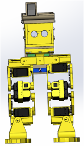
figure 1

Figure 1: Front View


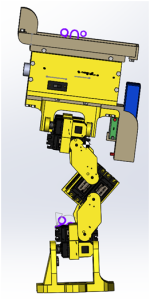
figure 2

Figure 2: Side View

Figure 1 and Figure 2 shows RoFi in a neutral standing position with the center of mass being the black and white circle.  Further research has led us to the conclusion that we want a lower center of mass to allow RoFi to easily traverse inclines and make sharp turns.  A possible solution is to lower the batteries back down to the feet or lower the backpack for the batteries,  however, we will not move the batteries to the feet per customer’s request.  Further testing in SolidWorks shows that lowering the backpack will cause servos to hit,  therefore, we have decided to keep the current center of mass.  Our current model will lead to wider turns and more exaggerated movements while traversing over inclines.

Spring 2016 RoFi: Prototype

Christopher Andelin (Project Manager)

Mario Ramirez (Systems Engineer)

Qui Du (Manufacturing Engineer)

Andrew Laqui (Electronics and Controls Engineer)

Henry Ruff (Electronics and Controls Engineer)

Table of Contents

Head Prototype

Qui Du (Manufacturing Engineer)

Objective

Since the 3D head is not printed yet, we realized that if we are to be successful, we need to begin coding the walking frames now.  We want to replicate the final 3D printed head so when we implement the 3D printed head there will be minimal errors with RoFi’s stability.

Materials

I decided to use an aluminum encased designer glasses box because it can easily be shaped and retain form.

figure 1

Figure 1: Aluminum Encased Box

Method

I measured the box and cut it to form the size of the SolidWorks 3D printed head. I bent the back of the box to form a battery holder.

figure 2

Figure 2: Prototype vs. 3D Model

Figure 3 shows the general look of the prototype.

figure 3

Figure 3: Prototype Head

Next, I cut holes into the front of the head for the ultrasonic sensor.

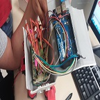
I attached the Arduino Mega board under the head top cover.

Figure 4 shows how all components have been organized in the head.

figure 4

Figure 4: Layout

Figure 5 shows the finalized prototype.

figure 5

Figure 5: Finalized Prototype

Conclusion

We were able to successfully have RoFi surpass the incline threshold with the prototype head.  We are hoping that replacing the prototype head with the 3D printed head will be successful too.


Spring 2016 RoFi: Mechanical Design Rev.2

Christopher Andelin (Project Manager)

Mario Ramirez (Systems Engineer)

Qui Du (Manufacturing Engineer)

Andrew Laqui (Electronics and Controls Engineer)

Henry Ruff (Electronics and Controls Engineer)

Table of Contents

RoFi 3D Modeling

Qui Du (Manufacturing Engineer)

Disclaimer: RoFi’s head components may change due to the in completion of the PCB layout. In this design, I remodeled RoFi’ legs, head and feet; finally, I will assemble them all in SolidWorks.

Introduction

Over the past few weeks, my team has been using the Arduino Mega board instead of the custom PCB with the Atmega chip, therefore, I designed RoFi’s head based on the Arduino Mega board. Since we will not be using the Arduino Mega, I will design the custom PCB to have the same dimensions as the Arduino Mega so that it will fit in RoFi’s head.

I will briefly cover how I designed the new head, feet and RoFi in SolidWorks.

Hardware Design

Head Top Cover Design

In order to secure the Arduino Mega, I modeled the screw holes position off of the Arduino Mega datasheet. In SolidWorks, I modeled the Head Top Cover by drawing centerlines and by using the Smart Dimension feature.

Figure 1: Screw Hole Position

Next, I determined the screw hole diameter and depth.

According to the Arduino datasheet, “all Arduino mounting holes are 3.2mm in diameter. They will accommodate M3-0.5”; I decided to use the M3- 0.5 screw for the Arduino Mega on the Head Top Cover.

Below, I provided information on the M3-0.5 screw type.

Source: http://www.spaenaur.com/pdf/sectionR/R11.pdf

Figure 2: M3-0.5 Screw

The datasheet says the diameter of the screw hole should be in the range of 3 (Ds) to 3.5mm (DA); I chose 3.02mm diameter for the screw holes in the Head Top Cover.

To determined the depths of the screw holes, I adding the width Top Head Cover and the Arduino Mega.

Figure 3: Screw Hole Depth

The best screw that is available for my design is the M3-0.5 with a length of 8mm.

The equation I used  to determine screw hole depth is (screw hole depth on the Top Cover) = (screw length) – (the width of Arduino Mega) => 6mm = 8mm – 2mm.

Figure 4: Finished Head Cover


Head Back Cover Design

I made two holes on the Head Back Cover of RoFi’s head for the power and USB port.

I used the reference dimention featureSmart Dimension feature in SolidWorks to show the dimensions of the holes.

Note: Because we are working in 3D, to measure the distance of two lines, I made sure the two lines were placed in parallel and in the same plane.  In the figure below, I added two centerlines as the two reference lines which are parallel and in the same plane which relates to the power and USB cord.

Figure 5: Power and USB Port Hole

To make it easier for me to determine the size of the back cover, I included the ultrasonic sensor.

Figure 6: Visualize Dimensions

I strategically placed the ultrasonic sensor and the Arduino Mega so that they fit comfortably in RoFi’s head. The thickness of the ultrasonic sensor is approximately 2mm and could easily hide in the head front cover; therefore the space for ultrasonic sensor is not necessary 22mm. In this design, I made the size for the Head Front Cover to be 59.34x51mm.

Figure 7: Assembly Analysis

Power Switch Design

Below is the design for the power switch and the location of the switch relative to RoFi’s head.

image8

Figure 8: Power Switch

image9

Figure 9: Power Switch Location

RoFi’s Hat Design

RoFi’s hat is used to hold the Android phone and is larger than RoFi’s head. The advantage of RoFi’s hat is that it allows the designer to only redesign the hat to fit a new phone without having to redesign the whole head.

image10

Figure 10: RoFi’s Hat

In Figure 10 you’ll notice that I designed the hat to be larger than the phone because I want to avoid friction that might scratch the phone.

Periscope Holder Design

Figure 11 indicates the position of the camera relative to the hat.

image11

Figure 11: Camera Location

Figure 12 shows the dimensions of the periscope.

image12

Figure 12: Periscope Dimensions

Figure 13 is the periscope holder that encases the periscope.

image13

Figure 13: Periscope Holder

Finally, I placed the periscope in a location that allows for proper viewing.

Figure 14 shows RoFi’ hat including the periscope holder.

image14

Figure 14: Hat

Battery backpack design

I used the same techniques for designing the periscope to design the battery backpack and body riser.

image15

Figure 15: Battery Backpack and Body Riser

Head Overview

Figure 15 shows the final product of RoFi’ head containing all the components.

image16

Figure 16: Head Overview

Figure 17 shows the exploded head view with all the components.

image17

Figure 17: Exploded Head View

Leg Design

To design RoFi’s legs I imported the 1501MG servo into SolidWorks from the manufactures website. I found there was a prototype of the 1501MG servo on grabcad.com which is available for download. I downloaded the servo and took measurements in SolidWorks and compared it with the measurement of the datasheet.

1501MG servo prototype measurements in SolidWorks:

image18

Figure 18: 1501MG SolidWork Dimensions

image19

Figure 19: Datasheet Dimensions

Figure 20 compares the prototype dimensions with the product datasheet dimensions.

image20

Figure 20: Servo Dimension Comparison

Figure 20 indicates there is a 0.3 – 0.5mm difference between the product datasheet and the prototype. I chose to use the product datasheet dimensions because it is slightly larger and can accommodate the smaller servos if needed.

Figure 21 shows the servo band which secures the servos in place.

image21

Figure 21: Servo Band

I used a protractor and ruler to measure the printed parts, and I corrected any flaws in my SolidWorks model.

image22

Figure 22: Knee Measurement

image23

Figure 23: Corrected Loose Servo Arm

Foot design

To minimize the mass of RoFi’s feet, I made holes in the bottom of the feet. Figure 24 shows the final product of the new foot design.

image24

Figure 24: Foot

Leg Overview

Figure 25 shows the complete view of RoFi’s legs with new feet.

image25

Figure 25: Legs

Leg diagram

Figure 26 shows the leg diagram.

image26

Figure 26: Leg Diagram

Completed Design

Figure 27 shows the completed design of RoFi.

image27

Figure 27: Completed Design

Sources for part dimension verification:

Atmega ADK: https://www.arduino.cc/en/Main/ArduinoBoardMegaADK

Samsung s6: http://www.gsmarena.com/samsung_galaxy_s6-6849.php

Batteries: http://www.valuehobby.com/gforce-2600mah-tx.html

Servo 1501mg prototype downloads from:

https://grabcad.com/library/power-hd-1501mg-rc-servo-1

Spring 2016 RoFi: Servo Driver, Accelerometer and Gyroscope Testing

Christopher Andelin (Project Manager)

Mario Ramirez (Systems Engineer)

Qui Du (Manufacturing Engineer)

Andrew Laqui (Electronics and Controls Engineer)

Henry Ruff (Electronics and Controls Engineer)

Servo Driver Testing

Andrew Laqui (Electronics and Controls Engineer)

Henry Ruff (Electronics and Controls Engineer)


Servo Driver Part Number: PCA9685

Link to Adafruit Servo Driver “Using the Adafruit Library” page https://learn.adafruit.com/16-channel-pwm-servo-driver/using-the-adafruit-library

ServoDriverFritzingBreadboard

Figure 1: Servo Driver Fritzing Diagram

ServoDriverFritzingSchematic

Figure 2: Servo Driver Fritzing Schematic

Link to Adafruit library for Fritzing https://github.com/adafruit/Fritzing-Library

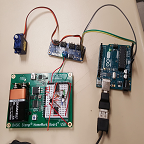
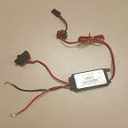
A Basic Stamp HomeWork Board with a built in 5V regulator was used to regulate the voltage from a 9V battery to power the servo. When the old Detrum UBEC regulator was used, the Tower Pro SG90 servo only made a buzzing noise; it was unresponsive. When we switched to the Basic Stamp HomeWork Board, the servo swept back and forth as it should.

ServoDriverCamera_compressed

Figure 3: Servo Driver Testing

The code was modified to only run the first servo (servonum = 0) rather than incrementing through 8 servos.

The code was modified from the Adafruit Servo Driver Library for Arduino Uno to match the pulse width of the Tower Pro SG90 servo.

Link to Tower Pro SG90 specifications http://www.servodatabase.com/servo/towerpro/sg90

#define SERVOMIN  500    // this is the 'minimum' pulse length count (out of 4096)

// Original value was 150. Value of SG90 is 500

#define SERVOMAX  2400 // this is the 'maximum' pulse length count (out of 4096)

// Original value was 600. Value of SG90 is 2400

Link to Adafruit Servo Driver “Hooking It Up” page https://learn.adafruit.com/16-channel-pwm-servo-driver/hooking-it-up

According to the “Hooking It Up” page, an electrolytic capacitor is added to handle quick changes in voltage. Since RoFi will be using 12 servos, a 1200 µF capacitor will be used.

At the moment, the servo driver has the pins that connect the GND, VCC, SCL, and SDA to the Arduino Uno soldered to the top of the board. These will have to be unsoldered and soldered again with the pins facing the bottom of the board in order to plug the servo driver directly into RoFi’s new PCB. If the pins are left the way they are, wires will be needed to jump the pins to the PCB.


Accelerometer and Gyroscope Testing

Andrew Laqui (Electronics and Controls Engineer)

Henry Ruff (Electronics and Controls Engineer)


Link to MPU-6050 test code http://playground.arduino.cc/Main/MPU-6050

MPU-6050FritzingBreadboard

Figure 4: Accelerometer and Gyroscope Fritzing Diagram

MPU-6050FritzingSchematic

Figure 5: Accelerometer and Gyroscope Fritzing Schematic

Link to MPU-6050 for Fritzing http://fritzing.org/projects/mpu-6050-board-gy-521-acelerometro-y-giroscopio

Once the MPU-6050 was connected according to the Figure 4 fritzing diagram and the code was uploaded to the Arduino Uno, the Arduino began displaying values for acceleration and tilt in the x, y, and z directions and temperature.

AccelGyroCamera_compressed

Figure 6: Accelerometer and Gyroscope Testing

Spring 2016 RoFi: Soldering Servo Driver

Christopher Andelin (Project Manager)

Mario Ramirez (Systems Engineer)

Qui Du (Manufacturing Engineer)

Andrew Laqui (Electronics and Controls Engineer)

Henry Ruff (Electronics and Controls Engineer)

Soldering Servo Driver

Qui Du (Manufacturing Engineering)


Due to the transition from the Arduino Mega to the Arduino Uno it is necessary that we implementh the servo driver to provide the pins we need.  Below are the steps I used in soldering our header pins to our 16 channel servo.


Tools

  • Solder
  • Soldering Iron Cleaner
  • Soldering Station
  • Soldering Iron
  • Unsolder Pump
image 1

Image 1: Soldering Tools

Servo Driver soldering process

  1. Turn on the soldering station and wait for the soldering iron to reach the desired temperature
  2. Clean the servo driver and header pins
  3. Install the header pins into the servo driver
  4. Heat the connection of the pin and the driver with the tip of the soldering iron for a few seconds, and then apply the solder at the connection
  5. Allow the solder to cool

Note: Only apply heat to the connection; do not apply heat to the solder.

image 2

Image 2: Servo Driver

Soldering Completed:

image 3

Image 3: Final Product

Source

https://learn.adafruit.com/downloads/pdf/16-channel-pwm-servo-driver.pdf.

Spring 2016 RoFi: Battery Trade-Off Study

Christopher Andelin (Project Manager)

Mario Ramirez (Systems Engineer)

Qui Du (Manufacturing Engineer)

Andrew Laqui (Electronics and Controls Engineer)

Henry Ruff (Electronics and Controls Engineer)

Battery Trade-Off Study

Mario Ramirez (Systems Engineer)


Desired run time: 20 minutes or 0.3 hrs

Battery Life T = mAh/mA

Current of one servo = 1408.315583mA

Current of all 12 servos = 16899.787mA


The power resource report, https://www.arxterra.com/spring-2016-rofi-preliminary-project-plan/#System_Resource_Reports, shows the amount of mA the system needs..  The project allocation is the amount of mA the battery will supply for 20 minutes of run time.  To find a proper battery we used the equation T=milliampere-hours/milli-ampere; where T is the amount of time in hours.  The amount of current drawn by one servo is about 1408.38583 mA and then multiplying that by 12 servos we get about 16899.787 mA. By manipulating the equation we get (16899.787mA) x (0.3 hrs) = 5069.9361 mAh which means we need a battery that can supply a minimum of 5070 mAh.  Since we will be using two batteries connected in parallel, each battery much be rated for at least 2534.96805mAh.  Our batteries voltage is of less concern because we will be using a voltage regulator.  More information on our voltage regulator is found here https://www.arxterra.com/spring-2016-rofi-voltage-regulator-trade-off-study/.

The preferred battery dimensions are  73 x 37 x 17.5mm (L x W x H);  the dimensions are obtained from RoFi’s battery slots located in his feet.  If needed, we can print a longer foot cap to allow for a longer battery instead of printing a whole new foot.

For the battery case study, we are looking for 2 batteries that are rated for 2600mAh each with the dimensions stated above.

A battery such as the VP 2600maH 7.4V Li-Po, http://www.componentshop.co.uk/7-4v-2600mah-25c-continuous-discharge-cranestock-lipo-battery.html, has the rated outputs our project needs to run for 20 minutes, but with the dimensions of 105 x 22 x 12mm.  The change in RoFi’s battery cap will be too long and interfere with RoFi’s walking capability.

From this, we have come up with three choices for our new batteries.

table 1

Table 1: Battery Comparison

Comparing all three batteries we decided the Glacier model’s thickness would not fit in RoFi’s current foot, and that printing a new foot is more difficult than finding a battery with a better fit.  Leaving the Gens Ace and Gforce models, we preferred the Gens Ace model sense we would need smaller changes in the battery cap length and .33 mm in thickness would fit properly in the dimensions of RoFi’s current foot. However, we could not find a store in the U.S. that had this battery in stock.  Therefore, we are going with the Gforce model and going to be ordering from, http://www.valuehobby.com/gforce-2600mah-2s-tx.html.


Sources

Glacier:

http://www.buddyrc.com/glacier-2600mah-2s-lipo-receiver-battery.html


Gens Ace:

http://www.hobbypartz.com/98p-2600-2s1p-2222-rx.html

Spring 2016 RoFi: Voltage Regulator Trade-Off Study

Christopher Andelin (Project Manager)

Mario Ramirez (Systems Engineer)

Qui Du (Manufacturing Engineer)

Andrew Laqui (Electronics and Controls Engineer)

Henry Ruff (Electronics and Controls Engineer)

Voltage Regulator Trade-Off Study

Andrew Laqui (Electronics & Control)

Delivering power to the servos requires a voltage regulator to transform the high voltage from the battery to a lower voltage for RoFi’s servos.

These larger voltage regulators are used instead of the much smaller voltage regulator chips because the small chips are rated for much smaller currents than what RoFi will be using. These Electronic Speed Controllers (ESC) are all rated for at least 5A. The following link details the difference between different regulators like UBEC ESCs and Opto ESCs.

http://blacktieaerial.com/opto-vs-bec-escs-use-ubec/

The following table compares the relevant specifications to determine which one will be the best for RoFi.

table 1

Table 1: Voltage Regulators

The Detrum Dynam 5A is the regulator that came with RoFi at the beginning of the semester, but after some testing and watching videos from the previous semesters, it has been concluded that this regulator did not deliver enough continuous current. According to the specifications, it was only able to deliver at the most 7.5A continuously. The RioRand® F-20A 20AMP and ARRIS Simonk 30A offer enough continuous current which will allow all twelve servos to draw their expected amount of 16.8A. This amount of current is verified by the Systems Engineer.

The following is the most updated Power Report.

table 2

Table 2: Power Report

Across the board, the RioRand® F-20A 20AMP is the preferred regulator since it is a much simpler design compared to the ARRIS Simonk 30A. Since the ARRIS Simonk 30A is an Opto ESC, it will still require an external UBEC to deliver the power to the servos.

The RioRand® F-20A 20AMP regulator was chosen mainly because it can deliver enough continuous current while also offering the simplest design. Although the Detrum Dynam 5A is already used on RoFi and the ARRIS Simonk 30A can deliver the most continuous current, the RioRand® F-20A 20AMP is relatively cheap because it can be ordered with Amazon Prime and also delivers enough continuous current.

The following are links to the websites of each respective regulator.

http://graysonhobby.com/dynam-5a-5-0v-6-0v-ubec.html

http://www.riorand.com/riorandr-f-20a-20amp-20a-simonk-brushless-esc-w-3a-5v-ubec-quadcopter-apm2.html

http://www.hobby-wing.com/arris-30a-opto-esc.html?gclid=COTjjObKwcsCFYqPfgodOV4NIQ


Spring 2016 RoFi: Power Trade-Off Study

Christopher Andelin (Project Manager)

Mario Ramirez (Systems Engineer)

Qui Du (Manufacturing Engineer)

Andrew Laqui (Electronics and Controls Engineer)

Henry Ruff (Electronics and Controls Engineer)

PTC Trade-off Study

Henry Ruff (Electronics & Control)


In the schematic design for RoFi, the PCB mainly entails connections to the main four components: bluetooth, accelerometer/gyroscope, ultrasonic sensor, and servos. For the twelve servos in particular, each one needs a polymeric positive temperature coefficient (PPTC) fuse, in order to protect them from drawing too much current at stall conditions. These PTC fuses can be implemented on the PCB itself, and for this purpose, several surface mount varieties were compared. The company Littelfuse provided the following guide for comparing potential components, and only the surface mount series were considered in this study. Datasheets for specific components within each series were found in the second link.


http://www.littelfuse.com/~/media/files/littelfuse/technical%20resources/documents/product_brochures/ec327-e_polyfuse_ptc.pdf

http://www.littelfuse.com/products/resettable-ptcs/surface-mount.aspx


The following table is a basic trade-off between the available series of PTC fuses, such that each series can be further looked into afterwards for a more specific trade-off series.

table 1

Table 1: Pros and Cons

The hold current (IHOLD) is the normal operating current of the servo, which for the PowerHD 1501-MG is 500mA at 6V, although ideally the servos will be supplied with 5V. The trip current (ITRIP) is where the PTC fuse will begin to impede excess current, desirably chosen to be less than the servos’ stall current of 2500mA at 6V. After looking at the cons, the 1206L, 1210L, 1812L, 2016L, and 2920L series were looked at for comparison, using components that would be the closest match for desired purposes. IHOLD would be up to around 1A to allow for variation due to operation and load, while ITRIP would be under 2500mA. For the following table, each component had functionally the same pros, therefore only cons and price were compared.

table 2

Table 2: Cons and Price

Mainly due to price comparisons, the Littelfuse 1206L110TH was then chosen from this study to be used on the PCB board.  However, higher numbered series had trip times up to 0.5 seconds as opposed to the 1206L110TH which had a trip time of 0.1 seconds, and was better because of which.