Spring 2014 Biped Final Thoughts

By Kevin Huynh, Project Manager

Tasks Complete:
Alternative movement code to the one provided by projectbiped and robot poser. Alternate code includes statically stable forward walk, left turn, right turn, and obstacle avoidance code.

Remote control of ROFIA through Arxterra. ROFIA can be commanded to stand up straight, walk forward, turn left, and turn right.

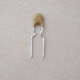
Servo overcurrent protection using polyfuses.

Ideas for future classes:
Develop the ability to walk backward or to walk sideways. Add these abilities to the Arxterra control panel along with options to move the head servos.

Consider using lower torque servos for joints that do not need to rotate as much weight to minimize current consumption. For example, look at how ROFI has the higher torque servos (Power HD 1501) to control the hip, upper leg and middle legs and lower torque servos (Towerpro MG99R) to control the
knee, lower legs, and ankles.

Look into implementing an IMU board into ROFIA for active control and the ability to react to external forces.

Minimize the mass unbalance caused by the USB cable from the phone to the Arduino.

Find a way to monitor the voltage of the LiPo batteries for safety purposes.

Simple control of Arduino using Arxterra

By Vinh-Khoa Ton, Control and Image Processing

The purpose of this experiment is to access the Arxterra control panel and to operate an Arduino board using the Microbridge connection through an Android phone.

For information about the Microbridge connection between Android and Arduino, please visit this blog post:
https://www.arxterra.com/simple-control-of-an-arduino using-an Android-phone/

A quick demonstration:
https://www.youtube.com/watch?v=D_rMULcm6uc&feature=youtu.be

How to set it up:
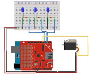
Use the schematic

schematic

The LEDs are on pins 2, 3, and 4 and the servo is on pin 5. The USB Host Shield v2.0 was needed for communication between the Android phone and the Arduino Duemilanove ATMega328.

Upload the Arduino code to the board (provided at the end of this post).

Open the ArxRobot app on Android phone and set up the connection with Arxterra, use the Microbridge connection type (for detail instructions please see Tommy’s powerpoint here:

http://csulb.edu/~hill/ee400d/Lectures/12_Arxterra%20Login.pptx)

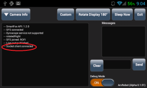
Connect the Android and Arduino using a micro-USB cable (the app should have a command “socket client connected”)

SocketClientScreenshot

In this example I created 3 custom commands (3 switches) to control 3 LEDs.

Log-in to Arxterra using the same credential that was used to connect to ArxRobot app.

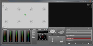
Go to the control panel:

controlpanel

At this point, the connection should be established. If we move a LED switch, the corresponding LED should turn on/off accordingly. If we hit a move button, the servo should respond accordingly.

Conclusion:
This experiment serves an important part in building a solid foundation for the final connection between our robot and Arxterra. After we successfully grasp the concepts of the communication between Android and Arduino, we can proceed to replace the move servo function with more complex movements to suit our need. The only limitation of what it could do is our imagination.

Arduino Code:
https://github.com/kh0/Spring-2014-ROFIA/blob/master/ROFIACode/ArduinoControlWithArxterra

Biped Movement Codes

By Kevin Huynh, Project Manager / Computer Systems and Software

Objective:
This blog will focus on the ideas behind how the code from projectbiped and the code from Spring 2014 handle the animation playback for walking and turning. It will also go into the reason for the switch.

ProjectBiped Code :
The most recent code can be found here:
http://www.projectbiped.com/prototypes/rofi/programs/arduino-action-playback

The code on project biped uses a timing system for the playback of the robot’s walking animation. The Action class holds all of the code for this movement method.
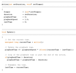
Update

The timing system starts with the function Update, which calculates playbackTime with the variables currentTime, lastTime, playbackSpeed, and duration. The currentTime variable is determined by the Arduino command millis() which returns the number of milliseconds since the microcontroller began running the program. The lastTime variable is equal to the previous currentTime value from the last time the walking animation frame was updated.

The playbackSpeed is determined by the user, based on the speed they chose when creating action frames with in RobotPoser. The calculation value is assigned to a variable called playbackTime, which is used in the function GetCurrentFrame to get the frame the robot should be on. If the calculation for playbackTime resulted in a value greater than the duration, the duration value is subtracted from the playbackTime, to create the animation loop.

Actions

In the most recent code, the duration of the action is determined by the numberOfFrames variable multiplied by 30, but in the code exported from RobotPoser, it is multiplied by 20. ~I’m not exactly sure what those numbers are, but they are likely values for milliseconds per frame. This would result in a time value. For the most recent code, the duration would be 2.52 seconds for the entire walking animation.
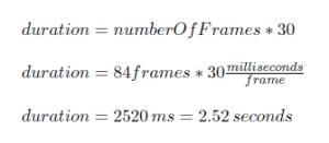
durationCalculation

GetCurrentFrame

Once playbackTime and duration are calculated, they are used in the GetCurrentFrame function. The parameter passed into GetCurrentFrame is a blank 1×12 array for containing the animation frame the robot will move to. The pointer sourceFrame points to the address of the frames array plus a value based on the playbackTime and numberOfJoints. From that address, the frame array takes 12 (numberOfJoints) from the frames array and the robot is told to move the servos to the specified positions.

Example:
When the robot starts up, the there is lastTime is set to 0. Suppose the value retrieved from the millis() command is 1000 ms, so currentTime = 1000 ms. The playback time is then equal to 1000 ms. Since the playbackTime is less than the duration of 2520 ms, there is no subtraction.

Then the GetCurrentFrame function is called and an empty 1×12 array named frame is passed into the function. From the equation, sourceFrame is equal to the address of the frames array + ((int)1000/30)*12. Since 1000/30 is type-casted to an integer type, the value is rounded down to 33, so sourceFrame = (address of the frames array) + 396. This points to the address of the first value of the 33th (if the first row is counted as the 0th row) frame of animation. Afterward, there is a for loop that loops 12 times to get all 12 values of the 33th row to put into the frame array for use in the SetServoPositions function. The frame array at 1 second should be:
{382, 70, -2837, 420, 4275, 1102, -1770, -472, 972, 0, -1520, -2612 }

Spring 2014 Code:
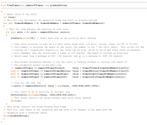
PlayFrames
The code used for Spring 2014 used a simpler method for playing the action frames. Rather than use a timing system to determine which frame the robot should be on, the new code uses two loops to run through every element of the action frame array. One loop runs through the elements of each row to update each servo. The second loop moves from row to row to progress the animation. A playbackDelay variable is used to determine the speed of the action progression. The action of moving the servos to their positions is based on the SetServoPositions function from the original code. The rest of the code is similar to the original code.

Reason for the switch:
When creating the animations and testing them out on RobotPoser, there were no significant issues with the playback. However, when attempting to have the microcontroller handle the animation in a standalone code, the robot would start on a frame in the middle of the walking animation, rather than start on the first frame.

This issue became more prominent as more code was added to handle the obstacle avoidance using the ultrasonic sensor, since the delays caused by the use of the ultrasonic sensor affected the timing of the animation. The problem was found when two things happened. The first was that the incorrect leg oved forward at the start of the playback. The second was the effect of the addition of the ultrasonic sensor code and the right turn code on the forward walk layback. After the robot turned right in response to an object 30 cm in front of it, the forward walk would start on the incorrect frame.

With the new program, the robot will always start on the first frame and run through the animation without skipping a frame. The addition of more code has been simplified because of the minimal impact on the animation playbacks, since the playback speed is controlled by a manual delay. In addition, the new code will hopefully be easier to understand at first glance.

Main Code (without Arxterra):
https://github.com/kh0/Spring-2014-ROFIA/blob/master/ROFIACode/MovementCode

Note: The Arduino code exported from RobotPoser does not include the functions that apply the calibrations to the frames of animation.

Simple Control of an Arduino using an Android Phone

By Vinh-Khoa Ton, Control and Image Processing

The purpose of experiment is to become familiar with the way an Android phone communicates with an
Arduino board using MicroBridge, an Android Debug Bridge (ADB) implementation for microcontrollers.
[Insert Android-Arduino.jpeg]

How it works:
The ADB protocol can either create a new shell or use the existing shell on an Android phone to send commands, read debugging logs, and forward TCP ports and Unix sockets. The Android phone reads data from a port that Arduino is connected to through the ADB. When a connection is lost (the application crashes, the USB cable is unplugged, etc), MicroBridge will try to reconnect to the device upon redetection.

Compatibility:
MicroBridge is designed to work with Android phones with version 1.5 and above. The following phones are confirmed to be compatible: ZTE Blade, Nexus S, Samsung Galaxy S, HTC Desire HD, HTC Nexus One, and LG Eve. A quick demonstration:
http://youtu.be/cX8whgZkdzk

How to set it up:
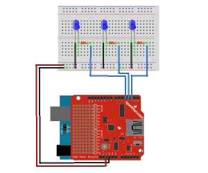
Using the schematic

schematic

The LEDs are on pins 2, 3, and 4. The USB Host Shield v2.0 was needed for communication between the Android phone and the Arduino Duemilanove ATMega328.

Some prerequisites:
Download Android SDK at http://developer.android.com/sdk/index.html
Download ADB library at: https://code.google.com/p/microbridge/downloads/detail?name=MicroBridge-Arduino.zip&can=2&q
Download Arduino code and Android app at: https://github.com/mitchtech/android_adb_simple_digital_output

A look into the Arduino code:
void setup()
{
   int i;
   for (i = 0; i < LEDcount; i++)
{
   pinMode(i+2,OUTPUT); // Set pins as output
   LEDState[i] = 0; // Init state to 0
}
// Init serial port for debugging
Serial.begin(57600);
// Init the ADB subsystem.
ADB::init();
// Open an ADB stream to the phone’s shell. Auto-reconnect. Use any unused port number, eg:4568
   connection = ADB::addConnection(“tcp:4568”, true, adbEventHandler);
}
void loop()
{
// Poll the ADB subsystem.
ADB::poll();
}
void adbEventHandler(Connection * connection, adb_eventType event, uint16_t length, uint8_t * data)
{
// In this example Data packets contain three bytes: one for the state of each LED
if (event == ADB_CONNECTION_RECEIVE)
{
int i;
for (i = 0; i < LEDcount; i++)
{
   if(LEDState[i] != data[i])
   {
    digitalWrite(i+2, data[i]); // Change the state of LED
    Serial.println(data[i],DEC); // Output debugging to serial
    LEDState[i] = data[i]; // Store the State of LED
   }
  }
 }
}

We need to create a connection to the ADB streams and receive events when connecting, disconnecting, or receiving data. We initialize the ADB in the Setup function by calling “ADB::init();”.


In the Loop method, we must sequentially poll the ADB layer by calling “ADB::poll();”

These 2 calls are the minimum requirements for establishing and maintaining a connection to our Android phone. Next, we want to open a connection with the phone by calling “connection = ADB::addConnection(“tcp:4568”, true, adbEventHandler);”. The first parameter “tcp:4568” forwards local TCP port to the Arduino. The second parameter “true” indicates whether the reconnection should be handled automatically. The third parameter is a callback method which functions as an event handler, which defines what events need to be triggered. We need to implement the event handler function to receive data from the shell. This function has the following parameters: connection, adb event, payload length, and payload data. In this example, we are trying to read command data from the Android phone to control the Arduino so we need to specify the “event == ADB_CONNECTION_RECEIVE”. In this example the data package contains 3 bytes according to 3 LEDs outputs. The nested code in the if statement determines which LED lights up.

Conclusion:
The MicroBridge is a simple solution that allows communication between an Android phone and an Arduino board. With this experiment, we take a first step in getting familiar with the ADB protocol. This allows us to expand our Arduino projects with more capabilities such as remote control of our robots with a friendly user interface instead of having to upload the code manually, or utilizing the built-in gyroscope, camera, and accelerometer of the Android phone for external sensors for our robots.

Sources:
http://mitchtech.net/android-arduino-usb-host-simple-digital-output/

Polyfuse Testing and Implementation

By Kevin Huynh, Project Manager / Computer Systems and Software

Objective:
The first test will verify whether or not the servos used will be protected from drawing too much current when they stall. The current level that will be considered dangerous for  the Power HD 1501MG servo is the stall current listed in the datasheet (2.3 A at 4.8 V). The second test will check how long it takes for the polyfuse to trip at its rated trip current and how much leakage current there is.

Test Materials:
1. Arduino MEGA 2560
2. Power HD 1501MG
3. 06R120BU Littelfuse Polyfuse
4. UBEC-5A-HV DC-DC regulator
5. Extech EX330 Digital Multimeter
6. 7.5 V 2.4 A Wall Power Supply
7. DC Bench Power Supply
8. Pliers

First Test Setup:
testSchematic1

First Test Procedure:
1. Set the circuit up as shown in the setup section. First without the polyfuse.
2. Choose a servo horn to place on the servo, the servo horn used for this test was the four point star.
3. Keep the servo from rotating the horn using the pliers.
4. Use either an Arduino program or the Robot Poser program (Biped) to control the servo. If using an Arduino program, have the servo continuously rotate between two points.
Sample code for rotating a servo can be found here: http://arduino.cc/en/Tutorial/sweep
If using the Robot Poser program, use the sliders to change the servo angle.
5. Record the current measured on the multimeter, then repeat with the polyfuse in place.

First Test Results:
Before connecting the polyfuse in between the UBEC and the servo, the highest current was approximately 2.25 A for a brief moment, then consistently about 1.8 A in later tests. While the stall current is not at the level specified in the datasheet for the Power HD 1501MG, the temperature seemed to increase slightly.
With the polyfuse, the highest current value achieved during the test was approximately 1.1 A, which is very close to the rated holding current of the polyfuse. Since 1.1 A is well below the stalling current found in the previous test and the datasheet, the current is at a relatively safe level. What was unexpected was that the polyfuse acted similarly to a constant current limiter, with the hold current being the limit.

Second Test Setup:
testSchematic2

Second Test Procedure:
1. Set the circuit up as shown in the setup section.
2. Set the voltage level of the power supply to the output voltage of your regulator (if applicable).
3. Increase the current to the rated trip current of the polyfuse and record the time it takes for the polyfuse to trip.

Second Test Results:
There were two tests conducted because of the results found in the first test. One test was used to find the trip time of the polyfuse at 2 A, the other was used to find the trip time of the polyfuse at 1.8 A. The trip time at 2 A, the rated trip current of the polyfuse, was approximately 7 seconds and the trip time at 1.8 A, the stall current of the servo, was approximately 12 seconds. The leakage current was around 0.09 A, which is far below the rated no load current and is unlikely to damage to the servo.

Conclusion:
Now that the polyfuse is confirmed to trip at both its rated trip current as well as slightly below the rated trip current, the polyfuses can be implemented into the robots. Although the trip times were somewhat slow, the polyfuses’ behavior as a current limiter at a current level slightly below the hold current (1.2 A) seems to avoid the need to trip at all.
Implementation (See the following picture for the schematic):

https://www.arxterra.com/wp-content/uploads/2014/04/servoProtection.jpg

implementationTop

implementationBottom
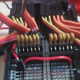
By soldering female headers into the protoshield and the inserting the polyfuses into those headers, the drawback of having to replace them after they trip is simplified. The polyfuse leads seemed to be a bit thin, so tape is recommended to help keep the polyfuses from falling out of the headers.

Test Videos Playlist:
Test Video

Servo Protection Methods Trade-off Study

By Kevin Huynh, Project Manager / Computer Systems and Software

Objective:
For Spring 2014, one of the requirements for the biped is to add in some form of servo overcurrent protection. The goal of this is to prevent the servos from drawing too much current, overheating, and destroying the control circuit boards inside of the case. A situation where this can happen is when the servos are stalled from reaching their desired position, but they continue to draw the maximum current possible–2.3 A at 4.8 V for the Power HD1501 MG servos from the following datasheet:
http://www.pololu.com/file/0J729/HD-1501MG.pdf

The LiPo battery pack used for ROFIA is the Turnigy 1300 mAh 2S 20C LiPo pack, found below:
http://www.hobbyking.com/hobbyking/store/__9165__turnigy_1300mah_2s_20c_lipo_pack.html

This battery pack can easily supply 2.3 A for all twelve of the servos if they were all to stall at the same time.

calculation copy

The above calculation shows the LiPo battery pack can safely and continuously deliver up to 52 A to the servos for about 3 minutes, which is more than enough to supply the stall current to all of the servos simultaneously (27.6 A).

Possible Solutions:
The two methods that were considered for servo overcurrent protection were foldback current limiters and resettable fuses.

Table copy

Solution Chosen for the Biped:
The resettable fuses were chosen for their low cost, simplicity of implementation, and because the specifications needed were easier to find on a polyfuse than a foldback current limiter IC. The drawbacks of the polyfuses can be mitigated by replacing the polyfuses as they trip by inserting the polyfuses into female headers soldered onto a protoshield, rather than soldering the polyfuses themselves. Since the stall current of the Power HD 1501MG servos is 2.3 A at 4.8 V, the 06R120BU Littelfuse was chosen.
http://www.mouser.com/ProductDetail/Littelfuse/06R120BU/?qs=sGAEpiMZZMsxR%252bBXi4wRUCTGuoKQj3D%2fwUhoRMyepPw%3d
http://www.mouser.com/ds/2/240/Littelfuse_USBR-36712.pdf

The main specification that was taken into consideration when choosing a polyfuse was the trip current. Since the stall current of the Power HD 1501MG servo is 2.3 A at 4.8 V, the polyfuse trip current was chosen to be 2.0 A. This ensures that the polyfuse will trip before the servo can reach the stalling current and damage itself. Other specifications, such as the hold current and maximum voltage, were satisfactory for the biped. The hold current rating of 1.2 A is well below the stalling current, so it is a safe operating current for the Power HD 1501MG servos. Since the output voltage of the UBEC is approximately 5.3 V and the operating voltage of the servos range from 4.8 V to 6.0 V, the polyfuse maximum voltage rating of 6 V is acceptable. The connections between the LiPo battery, UBEC buck converter, polyfuses, and servos are shown below. The servo pulse pins connect to digital pins on an Arduino Mega ADK.

servoProtection

Obtain and repair STL files

By Vinh-Khoa Ton, Control and Image Processing

Purpose of this process:
After obtaining the STL files for all ROFI parts, we needed a way to create a “clean” version of the modulated STL files. The purpose of this process was to eliminate all holes, gaps, and unclosed surfaces on the parts to ensure the quality of the 3D printed products.

Obtain the STL files:
1. Download the ZIP file that contains all the required 3D printed parts for ROFI at:
https://docs.google.com/file/d/0By_h1KTMNaWNNFlCLUJMY0dUbUE/edit
2. Extract all files into a folder.
3. Next, we will analyze and repair these files.

What software to use:
There is plenty of software available on the internet. We used Netfabb because it is free and easy to use, with or without installation of the program.
I. Without installation of Netfabb: this is a quick solution to repair a few parts without the need to download and install the application on computer.
1. Go to http://cloud.netfabb.com/

picture1

2. Click “Choose File” to select the STL that you want to fix.
3. Enter your email address (the repaired STL file will be sent to this email).
4. Choose the appropriate measurement unit that was used when the STL part was created (millimeters by default).
5. Click “I accept the terms and conditions mentioned below” and click “Upload to Cloud”. The page will open an upload progress dialog box shown below.

picture2

6. If successful, a confirmation will appear.

picture3

7. Open the email address entered above.
8. Click the download link provided in the email.

picture4

9. Click “Download” next to “Repaired file.”

picture5

10. Save the repaired file to computer.

II. With installation of Netfabb: a powerful software that allows users to easily repair multiple STL files.
1. Download the Netfabb Basic. Go to: http://www.netfabb.com/downloadcenter.php?basic=1
2. Select your computer operating system and click the download button.

picture6

3. Click the generated link to download Netfabb Basic.

picture7

4. Run the downloaded setup file “netfabb-basic_5.1.0_win32.exe” and follow the instructions
to install Netfabb Basic. (Note: Admin privilege may be required)
5. Open Netfabb Basic. Click Project -> Add part -> Go to the STL folder, select all of the parts and click “Open”. The software will load all of the selected parts, which can be viewed in the right-hand panel shown below:

picture8


Note: You can click the eye icon next to the part name to enable/disable its visibility.

6. Choose the part that needs to be repaired. From the menu bar, choose Extra -> Repair Part. A new item will appear below the original part.

picture9


7. Right click on the new generated item (called “Part Repair”) and click “Apply part repair”.

picture10

Choose “Keep old part” in the next confirmation window.
8. A new item will be generated. Right click on this part and choose Export part -> choose “As STL”.
9. Save the repaired file to your computer.
10. Repeat the above steps for the remaining parts.

Conclusion:
Netfabb is an easy to use and free software for repairing 3D printed parts while providing helpful tools for other 3D modeling functions such as an automatic repair tool, a slicing tool, and an analysis tool. We chose to use Netfabb because it provided enough applications for the Biped project to meet our requirements.

Ultrasonic Sensor Examination

By Vinh-Khoa Ton, Control and Image Processing

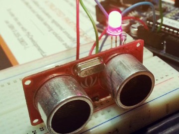
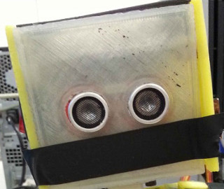
The purpose of this ultrasonic sensor examination was to determine the range and angle of the sensor detection. The ultrasonic sensor will be used as the eyes of ROFI and ROFIA for the purpose of avoiding obstacles. The Seeed Studio Ultrasonic Ranger v1.0 was the device chosen for this examination.

sensor

Examination Setup:
An Arduino ATMega328 was used to test the sensor. The connections between the ultrasonic sensor and Arduino are shown below.

schematic

The sensor was set at approximately 30 cm, the height of the robot. The sensor was placed on a hard and flat surface to ensure stability during the test. A black binder was used as an obstacle for easy angle adjustment (1 side is fixed and 1 side is adjusted).


test setup

The code used for the tests can be found in the dropbox link at the end of this post. The serial monitor, shown below, was used to record the distances at which the sensor detected an obstacle. The LED was programmed to light up if an object was within 30 cm of the sensor.

serial monitor

Detection Angle Testing:
A question that the test was designed to answer was: would ROFI and ROFIA be able to detect an object at their feet? To answer this question, the angle of the adjustable side of the binder with respect with the table was varied from being parallel with the table to being perpendicular with the table.

demonstration1

The highest distance value that the sensor detected for an angled surface was approximately 42 cm and any angle closer to being parallel with the ground resulted in the sensor being unable to detect the binder side.

demonstration2

The highest angle that the sensor could detect was approximately 36 degrees.

theta calculation

Detection Distance and Error Testing:
The sensor was tested with an upright object, as shown in the picture below, placed at different distances. The error between the sensor’s calculated distance and the actual distance was approximately

1 cm.

demonstration3
measured data

Conclusion:
The ultrasonic sensor is able to detect objects that are equal to and less than 36 degrees vertically away
from directly in front of it, given that the object is about 27.7 cm as shown in the angle testing section.
The ultrasonic sensor has about an error of 1 cm when detecting objects directly in front of it. The angle
detection brings up an interesting scenario. The ultrasonic sensor would have issues detecting objects
below it following any turning movements. The ultrasonic sensor also has problems detecting flat and
upright objects parallel to its line of sight. For the purpose of the biped project, however, we will be
avoiding these complications and will use it to simply avoid upright objects directly in front of it.

References:
Sensor specifications, background information, and Arduino code can be found here:
http://www.seeedstudio.com/wiki/Ultra_Sonic_range_measurement_module#Introduction

The Arduino code used to test the ultrasonic sensor can be found here:
https://dl.dropboxusercontent.com/u/20231161/Ultrasonic_Sensor_Testing.ino

Servo Examination

By Kevin Huynh, Project Manager / Computer Systems and Software

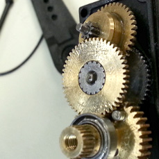
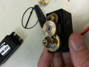
The purpose of this servo examination was to discern the reason for the servos malfunctioning. During the servo testing, it was discovered that three Power HD 1501MG servos were broken and the broken servos were closer to the feet of the robot, suggesting that the load was wearing out the servo by shear stress. We took apart the servos to figure out why the servos were actually breaking. Four servos were taken apart to examine the servo gears and shaft, three of the servos were the nonresponsive Power HD 1501MG servos mentioned in the servo functionality testing and one was a functional Power HD 1501MG servo as a base to compare the broken servos to. There seemed to be nothing physically wrong with the servos.

ServoGears

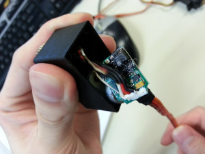
Next, we examined the circuit board on the other side of the servo. Two of the three broken servos had burned circuit boards, the third servo appeared to have no damage at all.

BurnedServo

Servo Examination Conclusion:
Since there seemed to be nothing wrong with the gears or shafts of the servo, it is unlikely that the servos were directly damaged by carrying the weight of ROFI. Since the circuit boards were burned, it is likely that the servos drew too much current and overheated. This is likely the result of the servos stalling, but continuing to draw a large amount of current in an attempt to reach the position specified by the programming. The constant draw of current eventually overheated the servo and burned the circuit board. We will be looking into ways to prevent the servos from drawing too much current from the LiPo batteries even if the servos stall, starting with a foldback current limiter.

Servo Functionality Test

By Elaine Doan, Systems and Test Engineering

Servo Functionality Testing
The objectives of this test were to verify that ROFI’s servos were working correctly. There are two servos that the CSULB Biped group is concerned with: the Towerpro MG996R servo and the Power HD 1501MG servo. These two servos were used in both ROFI and ROFIA, with ROFI having a combination of both servos and ROFIA using exclusively Power HD 1501MG servos.

Servo Test Materials
1. Arduino MEGA 2560
2. Towerpro MG996R and Power HD 1501MG on ROFI
3. UBEC-5A-HV DC-DC regulator

Servo Wiring Procedure
1. Connect the red wire to the positive terminal of the UBEC and the brown wire to the negative terminal of the UBEC DC-DC regulator. Do not connect either the red wire or the brown wire of the servo to the Arduino, there is a possibility that the servo will draw a lot of current and destroy the Arduino.
2. Connect the orange wire to an Arduino output pin. The orange wire is the control signal terminal of the servo and will allow you to control the servo with the Arduino.


Testing Code
The following code will command a servo on Arduino PIN 8 to rotate 60° clockwise within two seconds, then rotate 60° counterclockwise within two seconds. This process is repeated until the Arduino is turned off. The servo is assumed to have been centered before the test, but can be centered by using myservo.write(90).

#include <SPI.h>
#include <Servo.h>            // Include servo library

Servo myservo;               // create servo object to control a servo

void setup()
{
 myservo.attach(32);           // attaches servo on pin 8 to servo object
}

void loop()
{
 myservo.write(1);             // Move servo to 1 degree angle
 delay(2000);                  // Delay 2 seconds
 myservo.write(120);           // Move servo to 120 degree angle
 delay(2000);                  // Delay 2 seconds
}

Servo Test Conclusions:
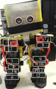
Three of the twelve servos on ROFI were found to be completely non-responsive. All of the nonresponsive  servos were Power HD 1501MG servos and tended to be close to the feet of the robot, suggesting that the load was responsible for breaking the servos. Following this is a diagram and table detailing the results of the servo test.


ROFI

Servo#           Servo Type                       Result
    1                      Towerpro MG996RC        Functional, rotates 90°
    2                      Power HD 1501MG           Functional, rotates 120°
    3                      Towerpro MG996R           Functional, rotates 90°
    4                      Power HD 1501MG           Nonresponsive
    5                      Towerpro MG996R           Functional, rotates 90°
    6                      Towerpro MG996R           Functional, rotates 90°
    7                      Towerpro MG996R           Functional, rotates 90°
    8                      Towerpro MG996R           Functional, rotates 90°
    9                      Towerpro MG996R           Functional, rotates 90°
    10                    Power HD 1501MG           Nonresponsive
    11                    Power HD 1501MG           Nonresponsive
    12                    Towerpro MG996R           Functional, rotates 90°

Demonstration Video
http://youtu.be/hO09e36LdrU

Datasheets available at:
Power HD 1501 MG: http://www.pololu.com/file/0J729/HD-1501MG.pdf
TowerPro MG996R: http://www.towerpro.com.tw/driver/drivers/Towerpro%20servo%20spec.pdf