Resource Report

By Tuan Vo, Project Manager


The weight of the aircraft must be of proportion to the amount of thrust the propulsion components can support.  This resource reports defines resource as all components, power, and mass requirements related to the aircraft.

Study by Juan Montano on components and mass provides us with total mass when powered by 4 fans.  Note the structure mass is estimated based on a previous model hexacopter using all the same components except the Tinyduino controller and number of fans. Also at the time of writing this document, the two batteries are being shipped. 

Part/#fans Measured weight (total)
Fan (4) 460g
ECS(4) 120g
Battery* 380g
Structure** 298g
XBee 7g
Arduino Nano 8g
IMU 2g
Components (excluding the body) 977g
Total: 1275g


Power resource: 

Part Voltage(V) Current
Electric Fan 14.8 16.5A @ 100% thrust
Arduino Nano 5V NA
XBee 2.8-3.4V NA
IMU 3.3V 10mA
LiPo 4s 14.8 14.8V 1300mAh (2600mAh total)
9V battery 9V 500mAh

* The Arduino Nano, XBee, and IMU operates under 50mAh which is negligible considering the current draw of the fans is many thousand times larger.


Task Description 

  • Receive parts from customer.
  • Evaluate parts for functionality. Make lists of parts needed.
  • Determine system requirements from mission objectives obtained from the customer.
  • Establish model of the aircraft using 3D modelling.  Create major components needed such as fans, microcontroller, and power source.
  • Write a Preliminary Design Document to give to customer to obtain funding.
  • Purchase parts.  Work with programming the microcontroller and wireless communication device, XBee, while waiting for parts to arrive.
  • Build a remote control device to receive user input and transmit via XBee to the microcontroller.
  • Build the body of the aircraft.  Cut the foam for the middle section and mold carbon fiber for the top and bottom piece.  Cut out as necessary.
  • Do systems tests that can be done without mounting the fans onto the body.
  • Mount fans onto the body and carry out the rest of the system tests.
  • Final adjustments to programming and structure based on tests.
  • Final presentation to the customer.
Level 2 Requirements

By Tuan Vo and Elaine Doan

Structural Subsystem Requirements

  1. The VTOL will use four 55 mm electric ducted fans per the request of the customer. The four fans gives enough thrust to lift themselves, the required electronics for control, and a body.  The body is estimated to be 298g from the fan selection study by Juan Montana and will give control of 36.5% thrust control. Using a margin of 15% for the mass of the body, we conclude that the body of the aircraft, not including any electrical components, must weigh less than 343g.
  2. Weigh the body and ensure this does not exceed 343g.
  3. After mounting all hardware and body along with the four fans, run the fans at 63.5% thrust.  The VTOL must achieve takeoff at this point.

Wireless Communication Requirements

  1. To wirelessly control the VTOL from a minimum range of 40ft, the VTOL system will include the XBee wireless RF module (maximum range of 100m or 300 ft.). The transmitter of the XBee wireless RF module will be connected to the remote control. The receiver of the XBee wireless RF module will be connected to the Arduino.
  2. Perform communication testing of the XBees using X-CTU. Make sure the “Baud Rate” of both the transmitter and receiver match each other. (https://sites.google.com/site/xbeetutorial/xctu).
  3. Using the remote control, command the VTOL to move forward, backward, up, down and side to side. The range of communication must be at least 40ft. 

Control System Requirements

  1. To achieve flight at the elevation of 8ft, four electronic speed controls will be used to increase and decrease the speed of each fan by 20% at a reference of 63.5% lift off thrust.
  2. Write a test code using the Arduino Nano to control the speed controllers and monitor it as it run at lift off thrust. Determine if the VTOL reaches desired height by comparing with an obstacle or measurement. The VTOL must stay at desired height with a deviation of 1/2 feet. 
  3. Raise or lower the speed of each fans individually by +/- 20% thrust.  Watch and confirm expected desirable increase or decrease in fan rpm.  This increase and decrease determines the VTOL’s directional movement.
    1. To support flight around the ECS 317 room, the VTOL will use the inertial movement unit. The inertial movement unit includes an accelerometer and gyroscope that will prevent the VTOL from undesired tilting, drifting or flipping during the flight around the room.  The inertial movement forms a closed loop control system that will stabilize the VTOL throughout its flight around the ECS 317 room. 
    2. Create a test program using the Arduino that will monitor the amount of tilt and acceleration present as the IMU is moved.
      1. To achieve flight (vertical lift off), weight is a major concern; as a result, the microprocessor of the VTOL will be the Arduino Nano.  The Nano weighs only 4 grams and at the same time its I/O ports are accessible to support four fans and receive inputs from both the user and the IMU.
      2. Specs of the Arduino can be verified at the link provided below: http://arduino.cc/en/Main/arduinoBoardNano#.UylKA_ldXGA

Power System Requirements

To provide enough power for the VTOL to fly around the ECS 317 class once (85.75 ft.), the main motor battery(s) must provide a minimum 1489 mAh to sustain required flight time. This will provide the speed controls and consequently the fans with enough power to provide 70% thrust for 2 minutes. The batteries chosen are two 1300mAh LiPo batteries.  Two speed controllers and two fans will be connected to one battery. 

  1. Verify at battery study and mAh ratings link: https://www.arxterra.com/motor-battery-selection/
  2. Before testing the batteries in actual flight, hook up the batteries to their specified fans.  On full charge, have the batteries power the fans at 70% thrust and record time from full to empty, signified by when any of the fans start to reduce in rpm. Time recorded must be longer than two minutes minimum flight time. 

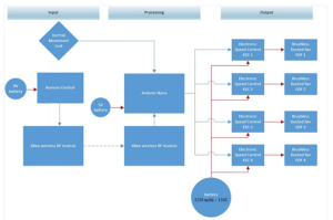
 System Block Diagram
4


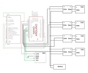
System Interface
5


Level 1 Requirements

Level 1 Requirements – By: Tuan Vo and Elaine Doan

  1. The VTOL will be designed with a flat conical frustum base and a dome (semi-sphere) attached at the top center of the conical frustum to model after the UFO from the movie, The Day the Earth Stood Still.
    1. Compare the 3D drawing created by team to a picture of the UFO, approved by the customer.
  2. The VTOL will fly once around the ECS 317 room (The room is measured to be 30 ft. wide and 23 ft. long. Assuming an oval flight path, distance to be travelled is 86.75 ft.)
    1. Test: Erect a perimeter with the same square dimension as room ECS 317.  Fly the VTOL aircraft around the inside perimeter one time.
  3. For safety and to avoid contact with people, the VTOL aircraft will fly at minimum elevation of 8ft from the ground.
    1. Test: Use measuring tape to indicate on the wall where 8ft is. Achieve vertical takeoff and hover the machine at 8ft, indicated on the wall.  Control and move the VTOL aircraft around and make sure that the elevation remains at 8ft with deviation of 0.5 ft. or less for the duration of flight.
  4. The VTOL will be controlled wirelessly from the minimum range 40 ft. (the distance from one wall to the opposite wall of the ECS 317 room).
    1. Test: Stand at one end of the ECS 317 classroom and wirelessly control the VTOL across the room to the opposite wall.

UFO Introduction with Mission Objective and Desired Look

By Tuan Vo, Project Manager

A vertical takeoff and landing (VTOL) aircraft is one that can ascend vertically into the air and land the same way.  There are many quadcopters and hexacopters that have achieved this feat. The use of electric ducted fans (EDF) to accomplish VTOL and hover flight is rare and have not been widely established.  This project will attempt to use EDF’s to achieve VTOL and hover flight in a fashionable manner.

Mission Objective:
Build a VTOL aircraft modeled after the UFO from movie The Day the Earth Stood Still.  The VTOL will utilize some of the major components provided by the customer and be controlled wirelessly to fly safely around a classroom.

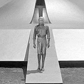
The desired look: (taken from the movie)
1


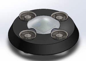
Rough 3D model:
2


Exploded View:
3

Determining the Number of Fans

By Juan Montano

Hello, this study will try to determine the number of fans that would be required for the UFO. The number of fans used in the UFO must meet the criteria of achieving lift off at 50% +/- ∆.

First, we determined the weight of each component currently provided to us by the customer:

Fan, ECS, Battery, Structure (Old), XBee, Tinyduino, Gyro

Component Weight
Fan 115g +/- 5
ECS 30g +/- 5
Battery 380g +/- 5
Structure

(top, mid,bottom)

400g +/-5
Xbee 7g +/-5
Tinyduino 8g +/-5
Gyro 2g +/- 1


Now, we try to determine how the mass of the structure will change as we decrease the number of fans. First, we will assume a linear regression of the diameter size of the UFO as we decrease the number of fans. We will then assume that the correlation between percentage of volume and mass is in a 1:1 ratio.

 From a different study, we determined the difference in diameter between 4 & 6 fans was between .7-1.5 inches. Using the max difference, we get ∆d=0.75”. Assume the UFO is a cylindrical shape, we will use the equation of a cylinder to determine the total volume of the UFO. We note that the old structure had d=11” and h=3”.


Fans Volume of UFO % Ratio to 6 fans Estimated UFO Weight
3   180.3/284.96*100=63% 253g
4   212.5/284.96*100=75% 298g
5   247.4/284.96*100= 87% 347g
6   284.96/284.96*100= 100% 400g


Now we determine the mass (g), and thrust for x number of fans.

Part/#fans 3 4 5 6
Fan 345g 460g 575g 690g
ECS 90g 120g 150g 180g
Battery* 380g 380g 380g 380g
Structure** 253g 298g 347g 400g
Xbee 7g 7g 7g 7g
Tinyduino 8g 8g 8g 8g
Gyro 2g 2g 2g 2g
Components 832g 977g 1122g 1267g
Total: 1085g 1275g 1469g 1667g

* We will assume a single battery as the power supply for the UFO, given to us from the customer. We may modify this, based on the battery trade-off study.

** Determined above using the old structure

Using the average thrust provided from last semester’s post burn studies, we have 502g of thrust provided by each fan.

Fans/Thrust Total Provided Structure+Components=UFO Lift UFO Control % Control
3 1506g 253+832=1085 421 28.0% +/-5
4 2008g 298+977=1275 733 36.5% +/-5
5 2510g 347+1122=1469 1041 41.5% +/-5
6 3012g 400+1267=1667 1345 44.7% +/-5


For the case of Multiple Batteries:

Here, we will assume that the mass of the battery will change with the amount of fans present. We will use the battery provided by the customer and determine the mass to be 380*x/6, where x is the current number of fans. Therefore, we will have:

Fans/Thrust Total Provided For Components For Structure UFO Lift UFO Control % Control
3 1506g 642 253 895 611 40.6% +/-5
4 2008g 850 298 1148 852 42.4% +/-5
5 2510g 1059 347 1406 1104 44.0% +/-5
6 3012g 1267 400 1667 1345 44.7% +/-5


In conclusion, we can see that 6 fans would give us approximately 50% thrust control. However, we would like to point out that there can be modifications made to the battery and/or the structure to provide ourselves with 50% thrust control using a smaller number of fans. Below, we will see how much weight the structure would have to be to provide that requirement.

Appendix A:

Here, we are going backwards to determine the maximum amount of weight our UFO (structure and/or battery combination) should be to provide a 50%+/- ∆ thrust control per number of fans. Using similar assumptions as above, we will note our fixed values.

Number of fans Fixed Thrust 50% Thrust Fixed Weight Remaining weight for battery/structure
3 1506 753 452 301
4 2008 1004 597 407
5 2510 1255 742 513
6 3012 1506 887 619

 This table above shows the fixed amount of total thrust we have and the set in weight determined by the components that are required in the UFO (Fan, ECS, Gyro, XBee, Tinyduino) and whose weight we can’t change. The remaining weight column shows how much weight the battery and structure should be to be able to maintain a 50% thrust control.

Since we can allow some leeway in the amount of thrust we should provide for control, we also show a 45% thrust control table below:

Number of fans Fixed Thrust 55% Thrust Fixed Weight Remaining weight for battery/structure
3 1506 828 452 376
4 2008 1104 597 507
5 2510 1380.5 742 638.5
6 3012 1656.6 887 769.6


Motor Battery Selection

By Jake Rice

UFO Abducted must be able to fly around a classroom using ducted fans driven by brushless DC motors. To achieve untethered flight, a battery must be used to power the motors. In selecting a battery for the UFO, the three main considerations are weight, maximum discharge current, and energy capacity. A lithium-polymer battery will be chosen due to the low weight and high discharge current of lithium-polymer batteries relative to other common types. Because the speed controllers for the motors are rated for 14.8V, the choices are limited to lithium-polymer batteries with 4 3.7V cells in series.

The main factor limiting battery choice is the maximum current draw of the motors. To maintain safe operation, the battery must be rated to supply more than the maximum current potentially drawn by the motors. Each motor has a maximum current draw of 27A, and the 4 motors have a combined maximum current draw of 108A.

In addition, the energy capacity of the battery must be large enough to ensure that the UFO completes its flight. Based on previous research, the UFO will be able to maintain level flight at under 70% of the maximum motor throttle, and at 70% throttle the motors draw 44.68A. To meet the 2 minute minimum flight time requirement, the capacity of the battery must be higher than 1489mAh.

The following chart compares several acceptable batteries. The battery purchased last semester is at the bottom of the chart.


Name

Cost

Weight (g)

Capacity (mAh)

Maximum Discharge Rate (C)

Maximum Current Draw (A)

Maximum Flight Time (min @ 70%)

Capacity/Weight Ratio (mAh/g)

Turnigy nano-tech A-SPEC G2

$49.77

296

2600

65

169

3.49

8.78

Turnigy nano-tech

$34.47

268

2250

65

146.25

3.02

8.40

ZIPPY Flightmax

$31.27

368

3000

40

120

4.03

8.15

ZIPPY Compact

$35.57

350

3300

35

115.5

4.43

9.43

Sky Lipo

$64.72

349

3000

40

120

4.03

8.60

ZIPPY Flightmax

$25.78

329

2650

45

119.25

3.56

8.05

Thunder Power G8 Performance Pro

$94.99

284

2700

45

121.5

3.63

9.51

MaxAmps LiPo

$109.99

327

3250

150

487.5

4.36

9.94


Of the batteries compared, the MaxAmps LiPo has the best capacity/weight ratio, the second-highest capacity and a far higher maximum current draw than any of the others. Using the Thunder Power or one of the Turnigy batteries would reduce the weight of the UFO. However, due to the higher capacity and the cost advantage due to the fact that we already have it, we should use the MaxAmps battery to power the UFO’s motors.