UFO Quadcopter Project Summary (Spring 2016)
Luis Valdivia (Project Manager)
Juan Mendez (Manufacturing Engineer)
Anthony Becerril (Systems Engineer)
Kevin Nguyen (Electronics Engineer)
Table of Contents:
- Project Overview
- Executive Summary
- System Design
- Experimental Results
- Subsystem Design
- Interface Definitions
- Custom PCB Design
- Hardware Design
- Software Design
- Verification and Validation Test Plans
- Project Update
- Project Demonstrations
- Project Blog Posts
- Concluding Thoughts
- Project Resources
Project Overview:
These series of summaries break down all the project efforts done throughout this semester of work. This overview follows our Critical Design Review with the Debrief details here.
Executive Summary
- Project Objectives
- The program objective is to ultimately achieve stable flight with our UFO Quadcopter while in operation. A 5th fan will be used as attempt to counter unwanted yaw rotation thus maintaining stability without surpassing weight limitations. The UFO Quadcopter will feature connectivity to an RC Controller and also a smartphone device via Bluetooth.
- Mission Profile
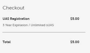
- Following safety requirements by CSULB and FAA, UFO Ab-ducted will fly vehicle in open field away from CSULB for a minimum of 7 seconds. The aircraft must display FAA registration code, FA3C74WXLT , while in flight. The user must also follow these safety requirements set by the FAA:
- I will fly below 400 feet
- I will fly within visual line of sight
- I will be aware of FAA airspace requirements: www.faa.gov/go/uastfr
- I will not fly directly over people
- I will not fly over stadiums and sports events
- I will not fly near emergency response efforts such as fires
- I will not fly near aircraft, especially near airports
- I will not fly under the influence
- Following safety requirements by CSULB and FAA, UFO Ab-ducted will fly vehicle in open field away from CSULB for a minimum of 7 seconds. The aircraft must display FAA registration code, FA3C74WXLT , while in flight. The user must also follow these safety requirements set by the FAA:
- The Design
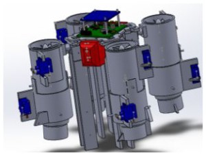
- Flap assembly
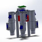
Figure 1.1 CAD Model of UFO quadcopter and thrust vectoring flaps
- Thrust Vector Control assembly
Figure 1.2 CAD Model of UFO quadcopter and thrust vectoring attachments
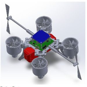
- Additional Fan assembly
Figure 1.3 CAD Model of UFO quadcopter and additional side fans
System Design
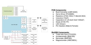
- System Block Diagram
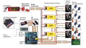
- Our system block diagram’s main component is our flight controller, the MultiWii 328P. Through use of our Lithium Polymer battery, we are able to power all our electronics as outlined below:
Figure 1.4 System block diagram of UFO quadcopter Spring 2016
Experimental Results
One experiment that was done was a torque experiment. This was done in order to find the torque that the yaw problem was producing and with the results we would be able to use to counter that torque. Research was conducted to create a proper test. A torque apparatus was then built where the test was conducted. The procedure for the test and results can be found in UFO Torque Test Spring 2016.
To figure out the necessary thrust from the 5th and 6th fan, we used the highest torque test reading .0515Nm along with the 6 inch fan rod and the torque formula using in physics class. Using the equation m=(Torque)/(g*radius) , we conclude m=(.0515Nm)/(9.8 *6 inches) –> m=.03448Kg is the necessary thrust counter the yaw rotation caused from the 4 EDFs. Since we used two side fans, we can set the output thrust for each fan to 17.24 grams. Using the buck converter, we turned down the voltage to produce that thrust per fan (2 fans). From the results we need to keep the output voltage from the buck to be roughly 1.91 volts to produce around 17 grams. Below we demonstrate the measure thrust values of the 5th and 6th fans with respect to different voltages.
| Voltage | Thrust |
| 2.97V | 33 g |
| 1.92V | 18 g |
| 1.9V | 14 g |
| 1.56V | 8 g |
Table 1.1 Demonstrates the relation between Voltage and Thrust for the additional side fans.
The current drain experiment consisted of a shunt resistor and a multimeter to measure the current draw. Since our motors draw large amounts of current, the multimeter was not able to take any proper measurements. To bypass this, a shunt resistor was used to measure voltage rather than current. After finding the voltage across the shunt, simple calculations can be done to acquire the current measurements. Details on this test can be found in Current Draw Spring 2016
Testing the functionality of Bluetooth vs. RC, an experiment was done by controlling the quad with each controller and incrementing the distance until connection was lost. The RC controller proved to be much more reliable and can communicate at well over 30 feet. The bluetooth communication often had trouble disarming the quad so it can’t stop the quad once things get out of hand. Information on Bluetooth Communication can be found the Bluetooth Communication: Smart Phone Applications Spring 2016 blogpost.
Details on RC Communication with the UFO can be found on our RC Control Spring 2016 blogpost.
Subsystem Design
- Interface Definition
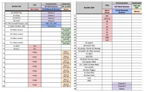
- Our interface definition is as follows:
Figure 1.5 Interface definition demonstrating ports used in the project
- Following our interface definition is our wiring tree where all hardware is laid out and details on connections. It is as follows:
Figure 1.6 Cable Tree of overall electronics for UFO Spring 2016
- Custom PCB Design
Fritzing:
Since PCB fabrication is a time-and-costly procedure, a prototype must be developed to ensure that the PCB would work the first time. The first step to the prototype is the Fritzing Diagram. The Fritzing Diagram maps out all the connections of the components on a breadboard.
Physical Board:
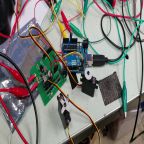
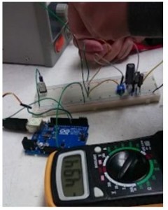
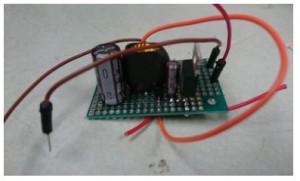
Continuing off the Fritzing Diagram, the physical prototype is implemented on a breadboard and tested using a power supply. The power supply was set to 14.8V to simulate the battery and the output was measured to be 4.94V.
Schematic:
After the prototype was confirmed to be working, the next step is to design the schematic for the PCB. The components had to be carefully chosen to include SMD packages. The components had to be changed multiple times since those packages were not available on DigiKey. Once all the required components were on the schematic and all the connections were wired properly, the Eagle files were given to the Manufacturing Engineer to do the layout.
Layout:
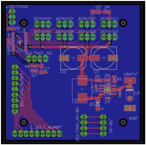
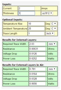
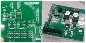
After designing a PCB schematic for the project, a layout had to be done in order to have it fabricated. The board was designed to be mounted on the UFO. Components were placed properly and trace widths were modified. Once the board was laid out, it was sent to be fabricated and then it was built. Further details can be found in UFO PCB Layout Spring 2016.
- Hardware Design
Several designs were taken into consideration in order to fix the yaw problem. The original design was to implement thrust vector control. This was done by adding attachments to the electric ducted fans and which would be able to control the direction of the thrust produced using servos. Unfortunately due to some unexpected issues, the idea of thrust vector control could not be implemented. Further details such as 3D models, dimensions for the original design can be viewed in Designs of 3D Printed Attachments Spring 2016.
Since this idea did not work, an alternative solution was thought of. The next approach was to add additional fans to counter the yaw problem. This did not give us issues as the previous design did. Further details about this alternate design can be viewed in Spring 2016 5th Fan Bracket Design.
Minor modifications were done to the UFO in order to increase the space for the battery while reducing the weight. Details can be viewed in Spring 2016 Re-design of Structure Rods.
Software Design
- First provide general block diagram of the software system, followed by arduino software modules responsible for communicating with the android app, specifically command and telemetry decoding and encoding.
- Subsystem software unique to product presented.
- Next talk about command and telemetry, (few critical subsystem software modules (1 or 2).
- For each module present, pseudo-code and/or flowcharts to provide an overview of the software
- Also provide sample code
Verification & Validation Test Plan Matrices
- Verification Matrix
| Requirement Number(s) | Shall Statement | Verification Method Summary | Verification Method | Results | Pass/Fail |
| 1.1, 2.1.1, 2.1.2, 2.1.3 | UFO Ab-ducted quadcopter shall maintain stable flight for at least 7 seconds. | Quadcopter will be timed via digital stopwatch from start of flight to end of flight. Flight will also be recorded to verify flight duration. Only flights that are stable with minimal yaw rotation will be accepted. Time must be within the tolerance of +/- 0.2 seconds (time between 6.8-7.2 seconds). | Test | TBD | TBD |
| 1.2 | Project shall be completed before end of Spring 2016 semester which ends on Friday, May 13th, 2016. | Project efforts shall be completed by Friday, May 13th, 2016 therefore no more work to be done thereafter | Analysis | Project was completed at the conclusion of Friday, May 13th, 2016. All documents and efforts were completed at the end of this day | Pass |
| 1.3, 2.3.1 | UFO Ab-ducted quadcopter shall comply by rules and regulations of the Federal Aviation Administration (FAA), Unmanned Aircraft Systems (UAS), and California State University, Long Beach’s College of Engineering’s flying policies. | To fulfill compliance of FAA, UAS and CSULB COE, the quad copter shall be registered as a flying object and shall not break any rules and regulations | Inspection | quadcopter is officially registered. It was registered under the identification number FA3C74WXLT. It also abides by the rules and regulations such as: | Pass |
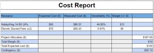
| 1.4 | Budget for this project shall remain below provided budget of 167 U.S. Dollars | Shall have approved budget with evidence via reciepts with the total cost lower than the provided budget | Analysis | Budget was submitted and approved at a total of $156.34 with supporting documents and information to complete the reimbursement process | Pass |
| 1.5, 2.5.1 | UFO Ab-ducted quacopter shall feature a light show of at least 3 unique patterns. | The lightshow shall be displayed and while on display is to give at least 3 unique patterns | Inspection | TBD | TBD |
| 1.6, 2.6.1, 2.6.2 | The UFO Ab-ducted quadcopter shall be capable of control with wireless communication for a range of at least 10 feet. | The wireless communication will be setup and tested with increasing distances away from the quadcopter being recorded | Test | TBD | TBD |
| 1.7, 2.7.1 | The UFO Ab-ducted quadcopter’s Printed Circuit Board (PCB) shall power at least one servo at 5 five volts via a buck converter. | Each pin and component on the PCB will be tested to give the 5 volts from the battery/voltage source. | Test | TBD | TBD |
Table 1.2
- Verification Matrix with requirement numbers
- Validation Matrix
| Requirement Number | Objective | Validation Method Summary | Validation Method | Pass/Fail |
| 1.1, 2.1.1, 2.1.2, 2.1.3 | UFO Ab-ducted quadcopter shall maintain stable flight. | Customer will evaluate stable flight of quadcopter. | Demonstation | |
| 1.3, 2.3.1 | UFO Ab-ducted quadcopter shall comply by rules and regulations of the Federal Aviation Administration (FAA), Unmanned Aircraft Systems (UAS), and California State University, Long Beach’s College of Engineering’s flying policies. | Customer will observe registration number and paperwork. | Inspection | |
| 1.4 | Budget for this project shall remain below provided budget of 167 U.S. Dollars | Customer will observe and confirm budget paperwork. | Inspection | |
| 1.5, 2.5.1 | UFO Ab-ducted quacopter shall feature a light show of at least 3 unique patterns. | Customer will observe lightshow. | Inspection | |
| 1.6, 2.6.1, 2.6.2 | The UFO Ab-ducted quadcopter shall be capable of wireless communication. | Customer will observe wireless communication via RC and bluetooth. | Demonstation | |
| 1.7 | The UFO Ab-ducted quadcopter’s PCB shall power at least one servo via buck converter. | Customer will observe servo powered via PCB servo driver. | Demonstation |
Table 1.3 Validation Matrix with requirements, objectives, and summaries
Project Update
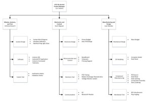
- Work Breakdown Structure
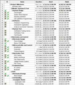
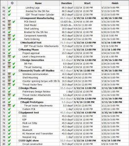
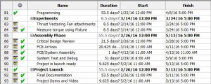
Figure 1.7 Work Breakdown Structure for the engineers in each division
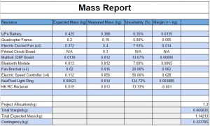
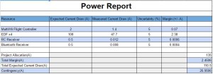
- Resource Reports
Figure 1.8 Resource report referring to Mass report for UFO Spring 2016
Figure 1.9 Resource report referring to Power report for UFO Spring 2016
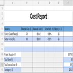
Figure 1.10 Resource report referring to Cost report for UFO Spring 2016
- Schedule
- Project Libre:
The project schedule was documented using, Project Libre. Every task was listed under each engineering division to display the engineer responsible for each task.
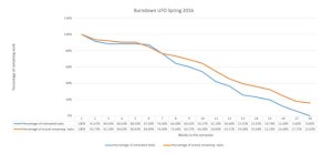
- Burndown
Project Demonstration
-
- Final Project Video
Project Blog Posts
Lipo Battery Safety Spring 2016
This post is a step by step guide on how to use the LiPo charger. Failure to handle the LiPo in a safe manner may result in damaged batteries….or worse self injury to user.
PCB Design: Schematic – Spring 2016
This blog post includes full detailed explanations on the components used within our PCB. Images of the components on Eagle Schematic are posted above each paragraph to give the reader a better understanding. Full schematic image is provided to show the connections between each component.
Current Draw Spring 2016
High powered motors are difficult to measure with a multimeter since the current draw exceeds the specifications of the meter. This post explains how to measure the current draw by measuring the voltage and resistance instead.
RC Control Spring 2016
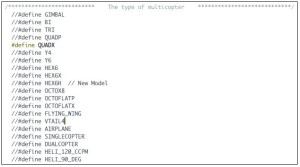
RC control is a must for quadcopters since bluetooth is short-ranged and unreliable. This post will guide the user through setting up the transmitter and receiver as well as setting the proper configurations on the MultiWii.
Prototype: Fritzing and Breadboarding – Spring 2016
To ensure that the PCB works the first time, a prototype is needed to test the functionality of the circuit. This blogpost overviews the process of creating the prototype circuit.
Spring 2016 Trade off study: 5 Blade EDF vs 10 Blade EDF
This blogpost compares the different thrust outputs from 5 Blade EDFs and 10 Blade EDFs. We demonstrate different throttle positions on our RC controller which correspond to different thrust from. We will finally see which fan is the strongest!
UFO Mass-Thrust Trade Off Studies Spring 2016.
Trade off studies were performed in order to determine how much weight the UFO can have before it got too heavy to lift off. An equation was found which allowed us to calculate the max weight. In order to confirm this equation with the UFO weight, servos, 3D printed attachments were added on.
Bluetooth Communication: Smart Phone Applications
Going over communication and controls, this post summarizes the smart phone applications used to receive data from the quadcopter flight controller sensors as well as use other applications to control the quadcopter rather than RC control.
Bluetooth Module Update Spring 2016
This details the bluetooth modules used previously and the new one implemented moving forward in series with the MultiWii flight controller and its GUI.
Verification and Validation Matrices Spring 2016 UFO
As detailed on the verification matrix, the following requirements have their own pass/fail results detailed:

1.1 – Stable Flight
1.2 – Project Completion
1.3 – FAA, UAS, CSULB COE Compliance
1.4 – Project Budget
1.5 – Lightshow
1.6 – Wireless Communication
1.7 – PCB
UFO Spring 2016 – EDF Area Coverage With Flap Length Calculations
We performed some calculations to determine the size of the allowable flap length on our EDFs. Using Microsoft Excel, we were able to determine an array of sizes with their corresponding output thrust.
Using Multiple servos without servo driver UFO spring 2016
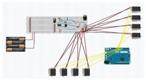
As a way of rapid prototyping our system without a servo driver, we wrote a blogpost to show an alternative to controlling servos. This method involves a simple wiring diagram with example code for various methods.
UFO Light Show Setup
The Neopixel ring is the aesthetic cornerstone of our wondrous quadcopter. This blogpost shows how to setup the hardware and software for the lightshow.
Project Preliminary Design Spring 2016 Millennium Falcon
This is our continuing on our research blog post which together is known as our Preliminary Design Review. It outline the beginning of all our work and sets up our fundamental understanding of project moving forward.
Spring 2016 Millennium Falcon Research
This post is an outline of our research of past quadcopter projects and possible solutions for approaching these solution.
Spring 2016 Millennium Falcon Preliminary Design Document
A Preliminary Design was put together for presentation by all group members. Here Program objective, Level 1 and 2 Requirements were defined along with Product Breakdown structures and project designs. Further details about the sections mentioned can be found in Spring 2016 Millennium Falcon Preliminary Design Document.
Concluding Thoughts:
Improvements for next semester:
- Next semesters should focus on flying the aircraft for more than 7 seconds.
- Consider a battery with a higher current capacity.
- Different fans. The ones we are using consume so much power at a small output thrust. Since we were extremely close to the weight limit, it seemed like the only option was to replace fans. Also, getting new fans with the option of 2 clockwise and 2 counter clockwise, will automatically eliminate the thrust and all excess hardware used to counter it. The multiwii knows how to talk to 2 clock wise and 2 counter clockwise fans, not all 4 clockwise.
- Include an emergency kill switch for the quadcopter in case disarming function does not work. When we tried using the Bluetooth app, BTCon2Drone, the disarm function would not register. To ensure safety to the user(s), include some sort of wireless command to disconnect the system from the battery.
Lessons learned:
- Don’t use the battery without the LiPo alarm. It is dangerous to overcharge a battery as well as over discharging it, ESPECIALLY A LIPO BATTERY.
- When we first started this project, no one was familiar with LiPo batteries. During one of our tests we over discharged a battery because we didn’t use the LiPo alarm. Luckily we were able to disconnect the battery the second we noticed a drop in performance. Fortunately no one was hurt, but our battery got a bit puffy from its original form.
- Always keep spare equipment around! Throughout the semester EDFs stopped working on us, ESCs burnt up and batteries failed. We were lucky enough to have a back up or order a replace before major deadlines. No one expects their equipment to fail, but anomalies are unpredictable to all electronic devices.
Things we could have done different:
- Implement different circuit to for servo driver. Ideally we chose a Buck converter to step down the 14.8V to 5V. Although, we did not realize the servos would hog enough current to prevent other servos from actuating. After testing our PCB we were able to control 1 servo while any additional servos would stall or jitter. We would advise further research of even current distribution between all servos.
- Upgrade the existing quadcopter frame. We didn’t realize this suggestion until after we noticed some of the carbon rods were caved in from over tightening of set screws. Since this frame has been passed down for a few semesters, it would be a good idea to check its condition and consider upgrading to a new frame.
Project Resources:
To best complete the transitioning of this project for future students, a resources folder was compiled into a Google Drive folder. The access to this folder is here: https://drive.google.com/folderview?id=0B5GCeIa4TgwtNjM0VXBoNTBTWDg&usp=sharing
It is best to read the “UFO_SP16_AResourceSummary” document and following through with all the additional, provided documents in the resources folder and get up to speed on the project’s progress.


