
Spring 2016 Velociraptor: Updated Walking Code #2 (Flash Memory)
By: Ashlee Chang (E&C)
Table of Contents
Fulfilling Requirements
Level 1 requirements #4 is stated as follows:
The Velociraptor shall be able to statically walk on all surfaces of the course.
Level 2 requirements #10 is stated as follows:
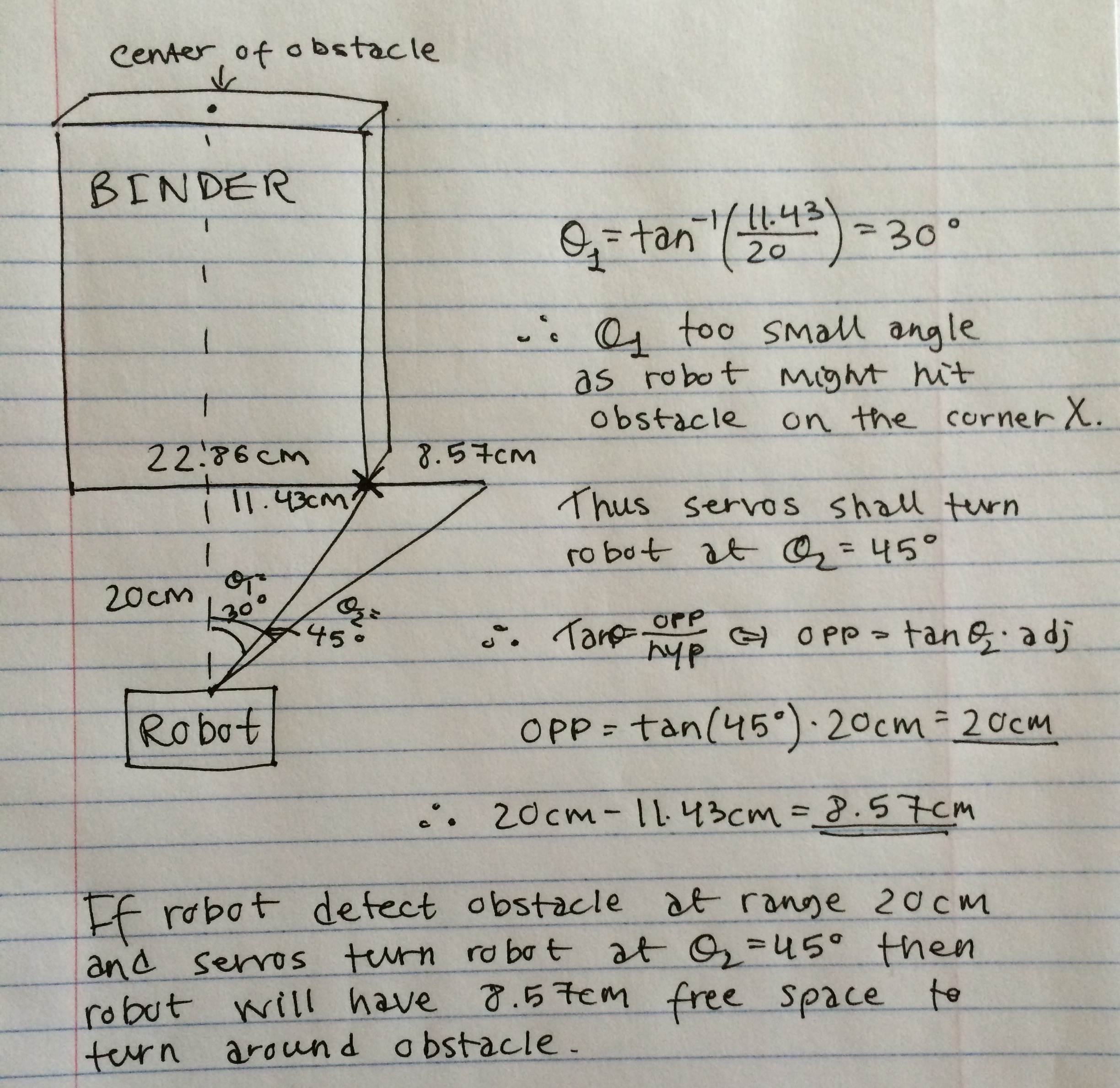
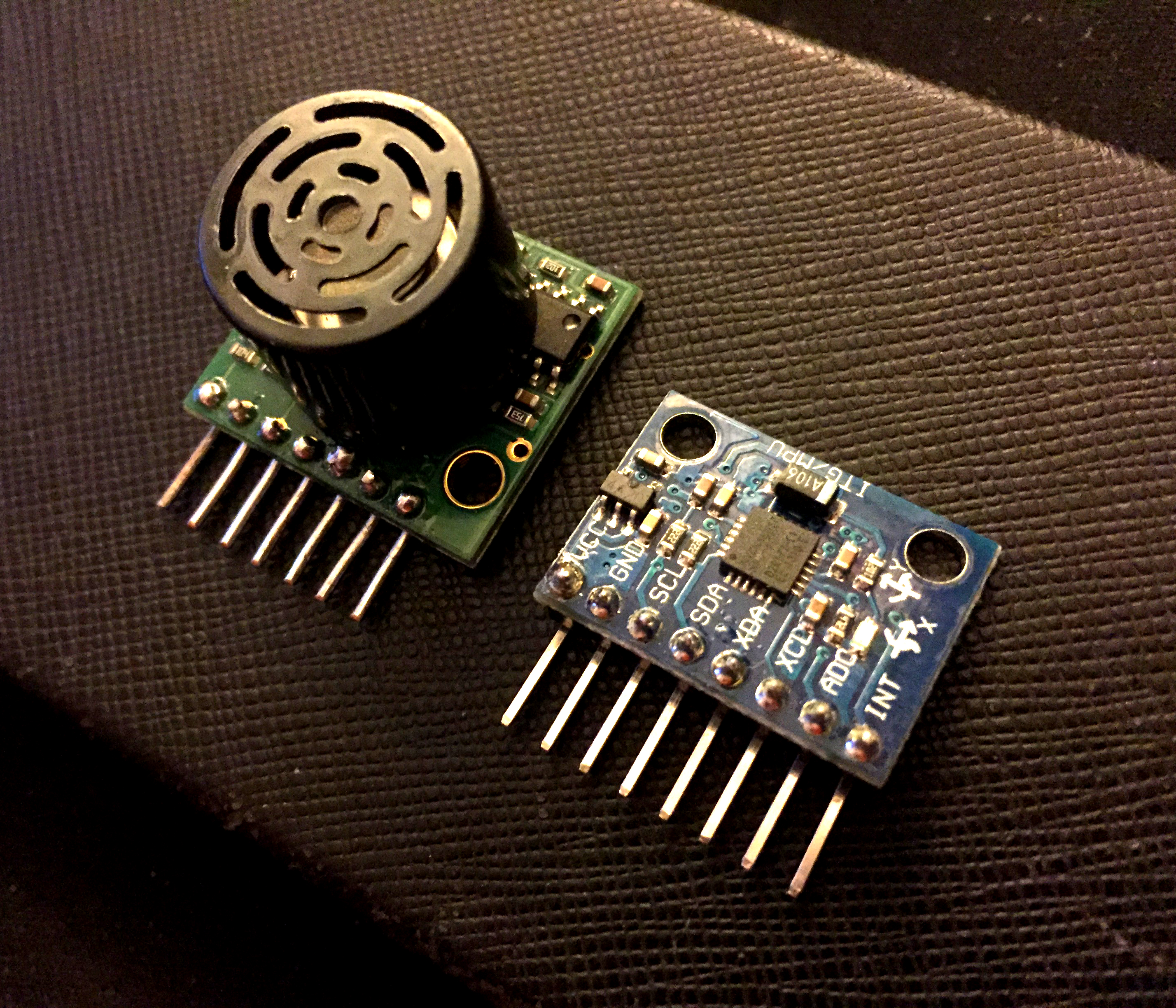
An ultrasonic sensor shall be implemented to the build of the robot to detect obstacles at a range of 20 cm.
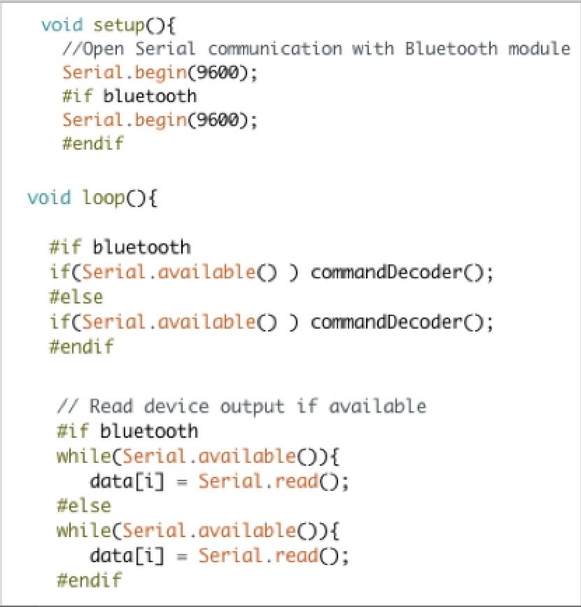
The Arduino software, which uses much of C++ programming language, will be used to construct and upload the code onto the Arduino microcontroller. The MB1030 ultrasonic sensor was implemented in this updated code.
SRAM Limitations
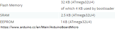
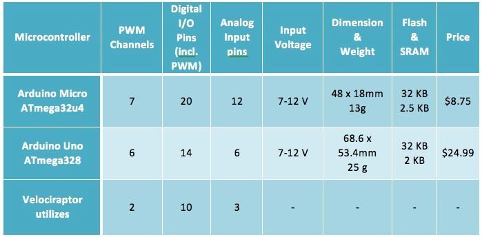
Arduino memory sizes
Looking at the Arduino micro specifications as listed on their website, it’s noted the SRAM (static random-access memory) memory is a mere 2.5 kB compared to flash memory at 28 kB (taking into account the bootloader space). The previous walking code could potentially “blow up” the microprocessor using while condition loops and many variables. To avoid this problem, moving the servo angles to flash memory is not only vital, but proved to be more convenient.
The How-To
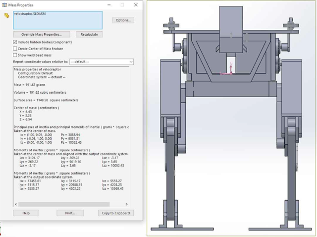
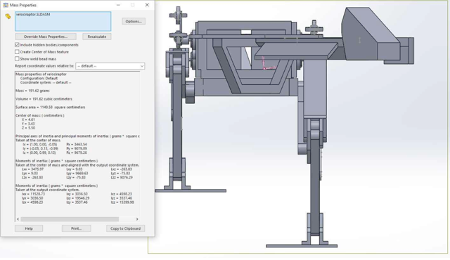
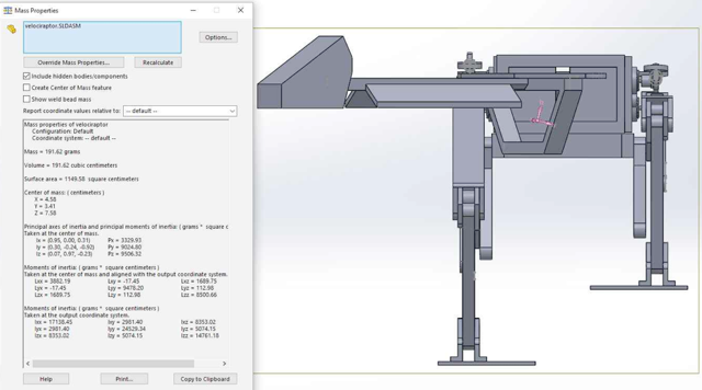
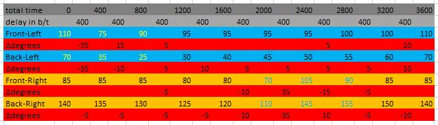
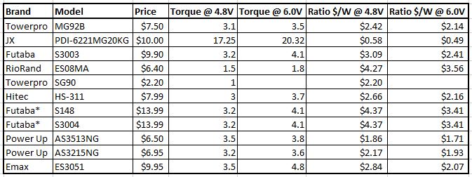
The first step is to transfer all servo angles over to an excel spreadsheet. It is important that in each column, all of these angles should be designed to be read at the same time. For example, in column 1, we see that front left = 110, black left = 70, front right = 92, etc. That means that at this point of time of 0 seconds, all servos will read at these respective angles. These indexes are related to the time the velociraptor is operating at. The velociraptor has 160 cells for each servo. The whole point of using excel is to better organize the angles and ensure that every servo has the same number of total indexes. For the second prototype, the new legs had different dimensions, thus some adjustments were required for the servo angles.
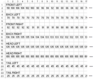
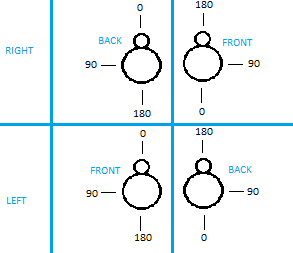
Servos and their servo angles
Next, save this excel file as .CSV. Re-open this file, but this time using notepad.

.CSV file opened in notepad
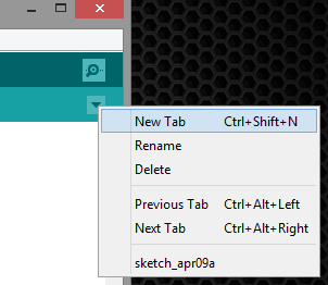
Now it is easy to grab these angles separated by commas and insert them into an array to be stored in flash memory. Next, on the right-hand side of the Arduino software, there is a down arrow button. Click this to expand some options, and click New Tab. Name this file according to the particular servo, and end the file name with “.h” to ensure it will in fact be an h-file. For example, one .h file the velociraptor used was flashFL.h (FL for front left servo).
Next, add “const unsigned int _[] PROGMEM = {_};” in this new .h file tab. The first _ will be the name of your .h file. The second _ will be the array copied and pasted from the .CSV file opened with notepad for the associated servo angle array. The command PROGMEM stores data in flash memory as opposed to SRAM memory.
![]()
Using PROGMEM in the .h file
All of these .h files should be in the same folder as the main code. Double check this, else the main code will not know where to look for these files. The .CSV file is not necessary to keep in the main folder, but is easy to refer back to in case any changes are to be made.
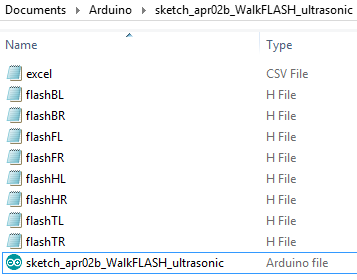
.h files in the main code folder
To allow the main code to utilize these arrays stored in flash, “#include_” must be stated in the beginning of the main code.
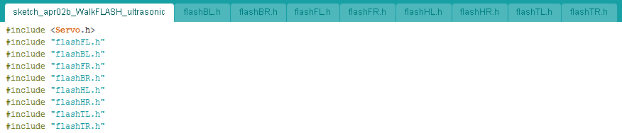
#include for the .h files
Last but not least, the array values are called from flash memory based on its index value. Use the function pgm_read_word(&_[i]); to access this data.
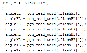
Reading from flash memory using indexes
Updated Walking Code
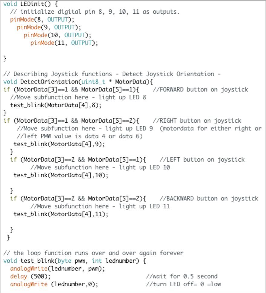
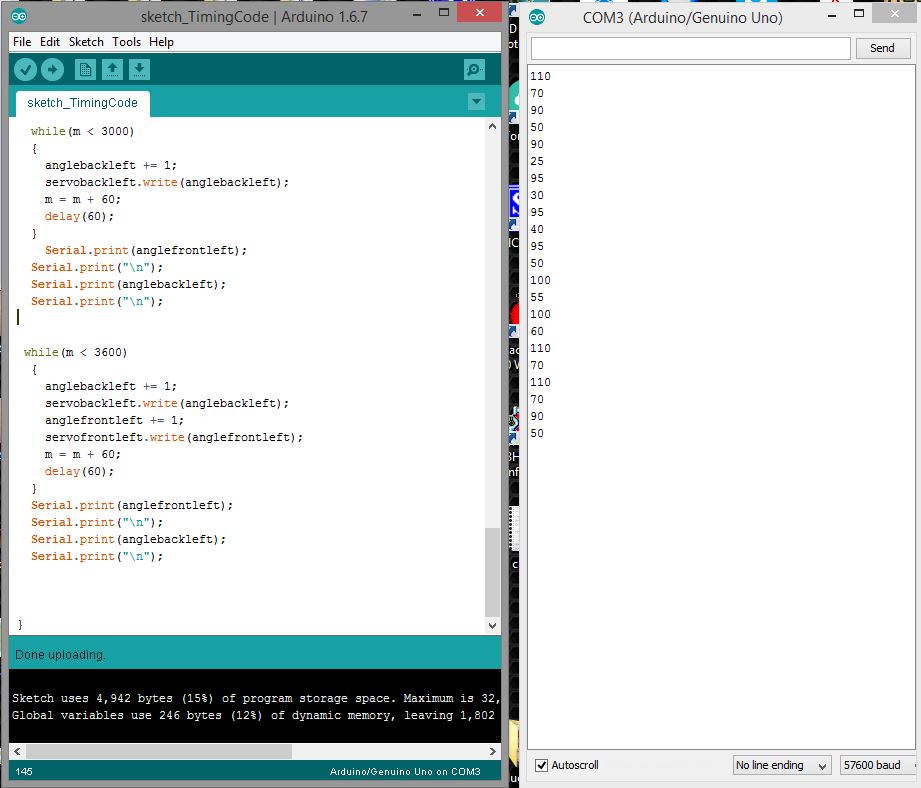
Below is the updated walking code.
Note how much cleaner and shorter the code is compared to using dozens of while loops to control the eight servos of the velociraptor.
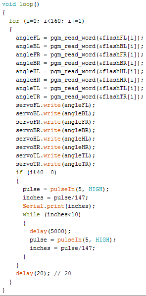
Updated walking code using flash memory
The main loop reads from all of the servo .h file arrays at one index at a time, then written to all eight servos at the same time. There are a total of 160 indexes per file, so after 160 iterations, the velociraptor will have taken two steps (one with each leg). Moving to flash memory not only saves SRAM memory, but also makes editing any servo angle at any point of time a piece of cake. A delay of 20 ms was chosen, but this could be adjusted to make the velociraptor walk slower or faster.
Also updated for the CDR presentation was implementation of the ultrasonic sensor. Every 40 cells read from the servos, there would be an object detection check. If there is an object within 10 inches of the ultrasonic sensor, the velociraptor would stop.
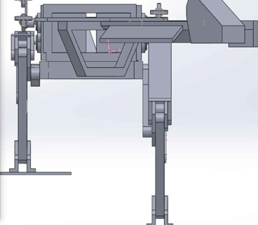
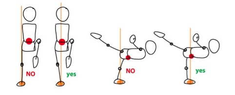
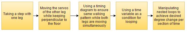
Also new to the code is the newly added head and tail. In order for the velociraptor to take a step, the center of mass must be moved from the center body to directly on top of the leg that will still be on the floor. Below is a table explaining the 160 cells of each array. For the first 40 cells, the left leg will take a step. This means the head and tail are already turned to the right so that all of the velociraptor weight is on the right leg that is on the floor. For the next 40 cells, both legs are on the floor as the servos both reinitialize in reparation for the next step while propelling the body forward. Because both legs are on the floor, the head and tail can now move from right to left. Etc.
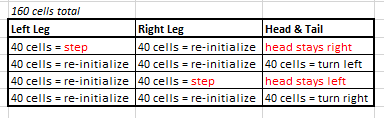
Implementing the head and tail


