Table of Contents:
Velociraptor Team
Khoi Vu (PM)
I. Responsibilities
II. Source Material
III. Literature Review
A. Level 1 Requirements
B. New Requirements
C. Project Cost
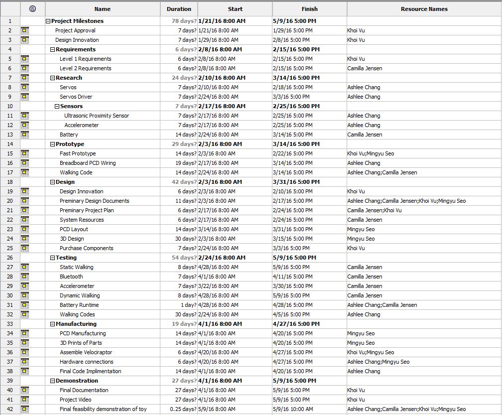
D. Project Schedule
E. Project Video
Camilla Jensen (S&T)
I. Responsibilities
II. Source Material
III. Works Cited
IV. Level 2 Requirements Review
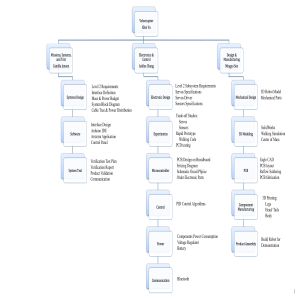
V. System Block Diagram
Ashlee Chang (E&C)
I. Responsibilities
II. Source Material
III. Literature Review & Application to the Velociraptor (Based on Fall 2015’s MicroBiPed)
A. MicroBiPed Level 2 E&C-Related Requirements:
B. MicroBiPed Fritzing Diagram
C. MicroBiPed Walking Code (C++)
D. MicroBiPed Servo Motors
E. MicroBiPed Accelerometer vs. Gyroscope
F. MicroBiPed Ultrasonic Sensor
G. MicroBiPed Microcontrollers
H. MicroBiPed Power Subsystem
Mingyu Seo (M&D)
I. Source Material
II. Works Cited
III. Literature Review
IV. Overview of Manufacturing and Design Responsibility
V. Notes on WBS (Work Breakdown Structure)
VI. Size & Weight
VII. Joints
VIII. Materials: (Prototype)
Velociraptor Team:
Khoi Vu (Project Manager)
Camilla Jensen (Systems Engineer)
Ashlee Chang(Electronics & Control Engineer)
Mingyu Seo (Design & Manufacturing Engineer)
Khoi Vu (Project Manager)
I. Responsibilities
First major task as the project manager is to work with the president (Chad Arnett) and the customer (Dr. Gary Hill) to define the project’s mission objectives.
- Once objectives are confirmed, the project manager would then work closely with the systems engineer to create programs and project level one requirements.
- As the requirements are set, the project manager will provide the president and customer with a preliminary cost breakdown of the project, the projected cost will be based on previous generations of the robot.
- After the preliminary cost is approved by the president and customer, the focus will be on the scheduling of team meetings, approving and reporting deadlines, and assigning tasks to individual engineers.
- All documentation of the project will be handled by the project manager; this includes editing trade-off studies, blogs, meeting minutes, and project videos.
- The project manager must assure that the robot’s performance meets the customer’s expectations.The project manager also ensures that the team’s contribution and performance to the project are at the highest.
II. Source Material:
- Final Documentation MicroBiped, 5/16/15, Final Project Cost, https://www.arxterra.com/final-documentation-microbiped/
- Fall MicroBiped Preliminary Project Plan, 10/1/15, Project Cost Estimation, https://www.arxterra.com/fall-2015-microbiped-preliminary-project-plan/
- Fall 2015 MicroBiped Level 1 Requirements, 9/18/15, Level 1 Program and Project Requirement, https://www.arxterra.com/microbiped-level-1-requirements/
- Fall 2015 MicroBiped Preliminary Project Plan, 10/1/15, Level 1 Requirements, https://www.arxterra.com/fall-2015-microbiped-preliminary-project-plan/
- Microbiped Final Documentation, 12-09-2015, Project Schedule, https://www.arxterra.com/fall-2015-microbiped-preliminary-project-plan/
- Microbiped Final Documentation, 12-09-2015, Final Video, https://www.arxterra.com/final-documentation-microbiped/
III.Literature Review:
A. Level 1 Requirements:
Fall 2015 MicroBiped did an amazing job in defining their level one requirements. While the majority of the requirements were met and exceeded, there were still minor mistakes that appeared. Some of the requirements were missing calculations that could have been included for further understanding of their thought process. For example, the incline degree was obtained from the obstacle without the explanation of how they got it. This confusion could be avoided if the team provided an image of the obstacle with measurements of the incline and some basic calculations. Below is the evaluation rubric of Fall 2015 MicroBiped Level 1 Requirement.
Evaluation questions for Fall 2015 MicroBiped Level 1 Requirements
B. New Requirements:
In the previous generation of MicroBiped robot, the ultrasonic proximity module was used. This sensor was added to the robot without a clear defined requirement for it. Therefore, this year’s team will implement a new requirement for the sensor that will enable the robot to completely stop when it detects an obstacle in its path and possibly having the robot navigate itself around the obstacle.
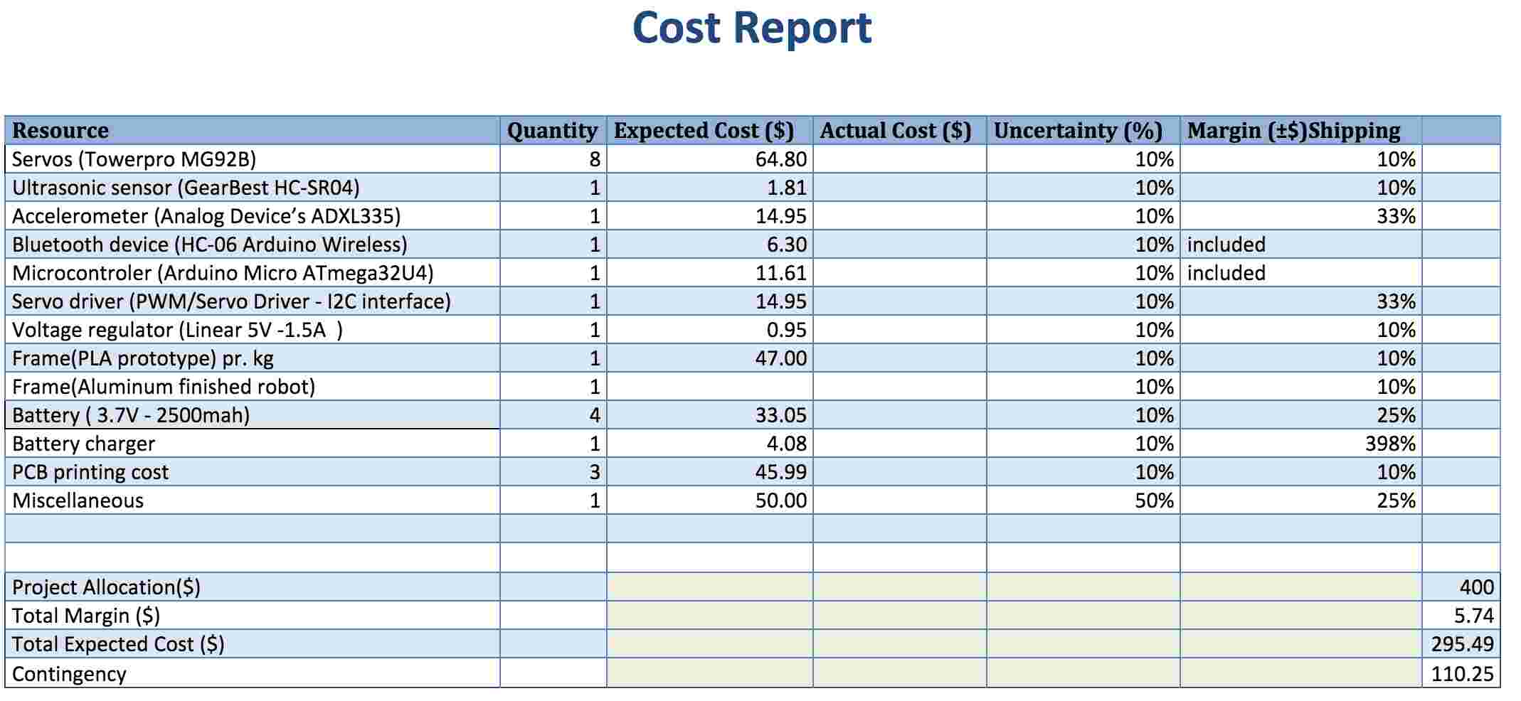
C. Project Cost:
Since Fall 2015 MicroBiped did not provide a final cost summary of their project, a preliminary cost of this year’s project will be a reflection of fall 2015 MicroBiped’s preliminary cost. Since, the preliminary cost is only an estimate, previous generations of MicroBiped’s project will also be looked at and taken into consideration. The Final Documentation of Spring 2015’s budget in particular was considered. In Spring 2015, their final cost of the project was $277.13 with some donations of parts. They collected a total of $122.00 in donations of parts. Therefore, the best estimation for this year’s project will be 400.00 with a margin of +/- 15%. The final estimation for this project will be approximately $400.00 +/- $60.
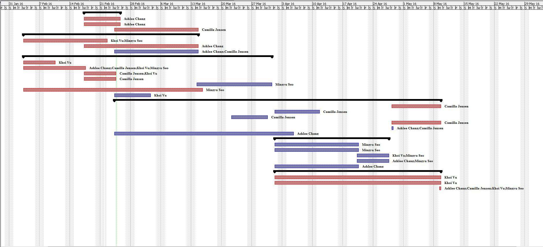
D. Project Schedule:
After taking into consideration the recommendation of the previous project manager, Paul Oo, and analyzing Fall 2015 MicroBiped’s schedule, the schedule of the project is critical to a project’s success. The Project Manager will collaborate with the systems engineer to create the most feasible schedule. In addition, it is important to also ensure that all engineers within the team follow the schedule closely to ensure the completion of the program.
E. Project Video:
The project video contains unnecessary humor that leads to its unprofessionalism. The project video should clearly demonstrate the engineering methods behind the project. Furthermore, subtitles would be a great addition to the video to clearly state what speakers are saying as some of the video was hard to hear with the background music.
Camilla Jensen (Systems Engineer)
I. Responsibilities
As a systems engineer, the main goal to make sure that the product and its system’s design meets the customer’s requirements by:
- Systems design process: Meeting both the design and financial requirements for the project by looking at the system’s resources that are available and its cost effectiveness. The level two requirements will be set, after the level one requirements are defined by the project manager and the systems engineer.
- Trade-off Studies: This method is used to determine the most feasible parts to design the system.
- Technical Management process: Configuring the communication between interfaces. For the Velociraptor, that task includes configuring the mobile device app, Arxterra Application, to control the Velociraptor and sending signals wirelessly to the Arduino via Bluetooth.
- This requires coding in C++ written in the Arduino IDE, configuring the Arxterra Application, and implementing Bluetooth communication.
- Product realization process: Generating product verification and validation test plans to ensure that each device will meet all defined requirements and validating it by testing prototypes until the final product can be manufactured.
Arxterra Application
- The Arxterra application can be downloaded to any android phone. Then the application is used to communicate with the biped robot via Bluetooth.
Bluetooth (HC-06)
- A Bluetooth component will be necessary to send data between the Arduino and a Bluetooth-equipped device such as an Android smartphone. Last semester used the HC-06 piece as well.
- Bluetooth HC-06 datasheet:
https://www.olimex.com/Products/Components/RF/BLUETOOTH-SERIAL-HC-06/resources/hc06.pdf
- Tutorial on how to setup the Bluetooth and Arduino:
http://www.instructables.com/id/Tutorial-Using-HC06-Bluetooth-to-Serial-Wireless-U/
II. Source Material
(1) Final Exam Fall 2015 Schedule Charts, 2/12/2016
http://web.csulb.edu/depts/enrollment/registration/final_exam/fall_chart.html
(2) Fall 2014 Biped Final Documentation, Detailed costs and schedule, 2/12/2016
https://www.arxterra.com/final-documentation/
(3) Project Biped, Programming, 2/12/2016
http://www.projectbiped.com/prototypes/prodos/programming
(4) Project Biped, Kinect, 2/12/2016
http://www.projectbiped.com/prototypes/fobo/kinect
(5) MicroBipedProject, Design of MicroBiped, 2/12/2016
https://www.arxterra.com/wp-content/uploads/2015/05/µBiPedProject-–-CDR_compiled.pdf
(6) The dinosaur-like biped robot TITRUS-III, 2/12/2016
https://www.youtube.com/watch?v=GxVv4WNlXMA
(7) Spring 2015 MicroBiped Introduction, Mission profile, 2/12/2016
http://arxterra.com/micro-biped-intoduction/
(8) Bluetooth interface to Arxterra Application, 2/12/2016
https://www.arxterra.com/bluetooth-interface-to-arxterra-application-in-progress/
III. Works Cited
(9) Day to day parenting, Normal attention span by age (October 21, 2013), 2/12/2016
http://day2dayparenting.com/qa-normal-attention-span/
(10) Age determination guidelines: Relating children’s age to toy characteristics and play behaviour (September, 2002), 2/12/2016
https://www.cpsc.gov/PageFiles/113962/adg.pdf
(11) Tokyo Institute of Technology Hirose and Yoneda Lab, The dinosaur-like biped robot TITRUS-III (2010), 2/12/2016
https://www.youtube.com/watch?v=GxVv4WNlXMA
(12) Friction and Coefficients of Friction, 2/12/2016
http://www.engineeringtoolbox.com/friction-coefficients-d_778.html
(13) United States Consumer Product Safety Commission, Toy Safety, 2/12/2016
http://www.cpsc.gov/en/Business–Manufacturing/Business-Education/Toy-Safety/
(14) NASA Systems Engineering Handbook Section 4.2 Technical Requirements Definition Start (page 40) and Appendix C page A: 279
IV. Level 2 Requirements Review
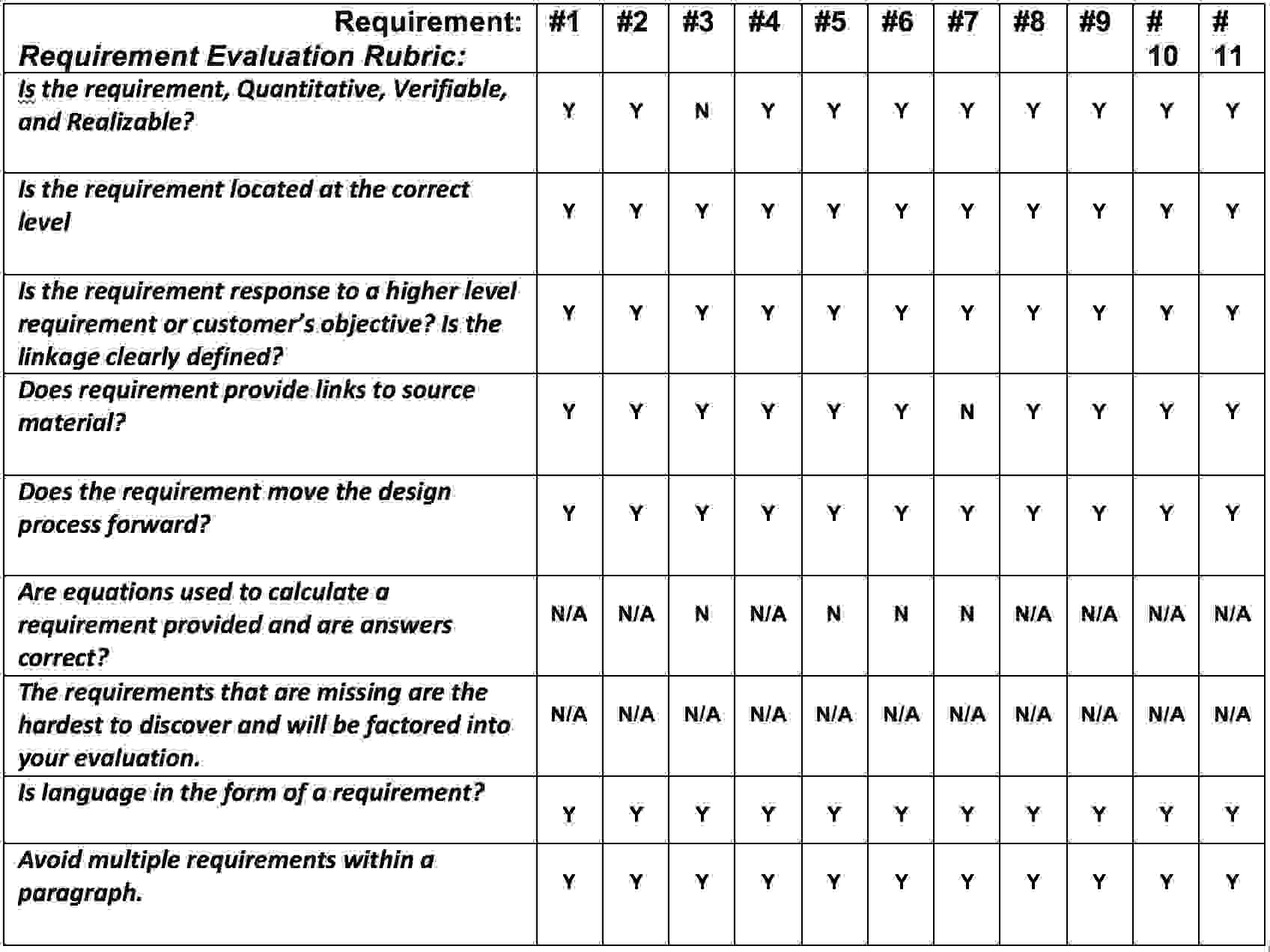
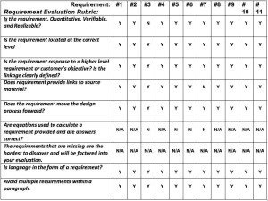
For the review of the previous semesters MicroBiped Level 2 requirements a list of questions from “The NASA Systems Engineering Handbook” [14] was used to determine the quality of each of the past level 2 requirements among others if these followed the tree structure and was linked to the level 1 requirements. To gain a better overview a table with the list of questions to which the requirements should answer yes to be a valuable requirement is shown in figure 1:
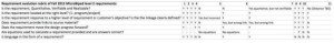
Evaluation questions for Fall 2015 MicroBiped Level 2 Requirements
For the first part of the level 2 requirements [1-4] the Fall 2015 MicroBiped project group did a good job stating correct quantitative requirements (Shall-statements), with accurate linkage to level 1 requirements and sufficient source material to verify facts.
On the second part of the level 2 requirements [5-11] the quality of statements fell short on some questions and these will be gone into detail. For the general part most of the requirements did not indicate the “shall”- statement to form an actual requirement.
Requirement #5:
To maintain balance by incorporating head and tail to the chassis is not a quantitative requirement. The link provided[4] was inaccurate referring to how the FOBO could be controlled by a human operator using Kinect and the Motion Control application, but neither was used for the MicroBiped. The link didn’t provide any verification for the incorporation of head and tail for the robot for it to improve its balance. Neither was any equations applied to verify that instalment of head and tail to the chassis would improve balance and therefore the linkage to level 1 req. 4 is also incorrect.
Improvement:
A back of the envelope calculation could verify if the instalment of head and tail will equal out the weight of the corps and thus improve the balance of the MicroBiped Hence the linkage to level 1 req. 4. Could be made since it will stabilize the travelling on two legs.
Requirement #6:
The source links provided[5,6] for the dimensions of the Biped doesn’t tell the actual dimensions of the Biped and therefore are not useful. Common logic can verify that the two-servo to one leg requirement will reduce the dimensions from the past robot using 6 servos per leg but there is no verifiable equations proving it correct. Thus the linkage to level 1 req. 5 is inadequate.
Improvement:
Again as for req. #5, a simple back of the envelope calculation of the dimensions of the past robot with 6 servos per leg vs. 2 servos per leg could verify if the this improvement will reduce the dimensions of the robot and thus verify the linkage and categorize as a MicroBiped.
Requirement #7:
The source material provided [7] doesn’t provide any information on the function of the gyroscope but only information on the mission profile of the Biped and the course it shall complete. Therefore the linkage is invalid and cannot be used to verify the linkage to level 1 req. 6 and 7.
Improvement:
Provide correct source material for the gyroscope indicating its function; how it will preserve the chassis balance when moving up an incline and over obstacles and thus verify the linkage to level 1 req. 6 and 7.
Requirement #8:
Good valuable requirement only stated wrong.
Improvement:
Correct to “shall”-statement.
Requirement #9:
Good valuable requirement. The source material provided indicates sufficient equations to calculate the friction of different terrains and thus verify level 1 req. 8. Statement is not of a requirement
Improvement:
Correct to “shall”-statement for the form of a correct requirement.
Requirement #10:
Good valuable requirement only stated wrong. No equations needed to verify this requirement and thus not provided.
Improvement:
Correct to “shall”-statement.
Requirement #11:
“The MicoBiped must avoid walls at a distance of (TBD). Determined by the mission profile.” This statement is utterly not quantitative, verifiable nor realizable. A requirement cannot contain a “To be determined” sentence as this is not giving anything to verify or realize and thus does not move the design progress forward but stall it. The requirement contains no equations but none are needed and no source material is provided. Likewise it is missing an actual link to the mission profile.
Improvement:
The distance of what the robot must avoid walls at can be determined from the customer’s objective or from the sensors range or and thus the requirement become quantitative. Provide a link to site of sensors and the requirement becomes verifiable. Last implement sensors and test prototype if requirement is realizable.
V. System Block Diagram
The system block diagram of the MicroBiped shows a good outline of how every device of the robot is connected to the brain, the microprocessor, and the brain distributes the commands from the control panel to the servos and sensors sends signals back to the brain to stabilize and navigate the MicroBiped successfully.
Ashlee Chang (Electronics & Control Engineer)
I. Responsibilities
The electronics and control engineer is primarily responsible for the selection of sensors, actuators, and power subsystems; laying out the circuit schematic; and compiling the C++ code necessary to control the operations of the velociraptor.
- Sensors, actuators, and power subsystem options will be compared, selected, and then tested using a breadboard. Pros, cons, and trade-offs will be considered in the making of the decision. Parts under the responsibility of electronics and control for the velociraptor include: the battery, arduino + atmega32u4, ultrasonic sensor, servos, and the accelerometer.
- Upon researching the requirements for the velociraptor’s electrical components, the fritzing diagram is ready to be laid out and tested on a breadboard. For circuit simulation, LTspice and Eagle CAD will be downloaded and utilized to map out the circuit before testing and future fabrication. After success, the results are given to manufacturing and design to implement the schematic on a printed circuit board.
- C++ will be the primary coding language used to control the velociraptor.The ultrasonic sensor, accelerometer, and remote will be used as inputs to the microcontroller, and the program will carry out the necessary algorithms and relay the information to the servos to carry out walking and balancing operations.
II. Source Material
[1] Arxterra website, Fall 2015 MicroBiPed Summary
http://arxterra.com/?s=microbiped
[2] Arxterra website, Fall 2015 MicroBiPed Walking Code
http://arxterra.com/fall-2015-microbiped-walking-code/
[3] Arxterra website, Fall 2015 MicroBiPed Motion Sensor
http://arxterra.com/fall-2015-microbiped-motion-sensor/
[4] Arxterra website, Fall 2015 MicroBiPed Battery Updatae
http://arxterra.com/fall-2015-microbiped-battery-update/
[5] Arxterra website, Fall 2015 MicroBiPed Distance Sensor
http://arxterra.com/fall-2015-microbiped-distance-sensor/
[6] Arxterra website, Fall 2015 MicroBiPed Microcontroller
http://arxterra.com/fall-2015-microbiped-microcontroller/
[7] Arxterra website, Fall 2015 MicroBiPed Servo
http://arxterra.com/fall-2015-microbiped-servo/
[8] Arxterra website, Fall 2015 MicroBiPed Preliminary Design Documentation
http://arxterra.com/fall-2015-microbiped-preliminary-design-documentaion/
[9] Arxterra website, Fall 2015 MicroBiPed Power Budget
http://arxterra.com/fall-2015-power-budget/
III. Literature Review & Application to the Velociraptor (Based on Fall 2015’s MicroBiPed)
A. MicroBiPed Level 2 E&C-Related Requirements:
(4) To facilitate all the algorithmic functions of a walking BiPed, the Arduino MICRO with an ATmega 32u4 Microcontroller will be used to meet Level 1, requirement 4.
Verification: With the reduced amount of servos, the amount of PWM pins required are also reduced. Therefore the Arduino MICRO is the better choice in comparison to the Arduino UNO.
(5) To maintain balance (while retaining core features of a BiPed), installment of a head & tail will be incorporated to the chassis to adjust the center of balance and thus meet Level 1, requirement
Verification: The reduced freedom of movement also means less ways to balance while moving. To compensate, alternative appendages can be attached to maintain the center of balance while moving.
(6) To reduce the dimensions of the BiPed, the μBiPed shall use a two-servo to one-leg system to eliminate bulkiness and meet Level 1, requirement 5.
Verification: The previous semesters utilized 6 servos per leg to increase the articulation, but increased the bulk, weight, and the height. A more mechanical approach will be used to control the legs to imitate a velociraptor model.
(7) For the μBiPed to detect and adapt to inclines, a gyroscope shall be used to preserve chassis balance and meet Level 1, requirements 6 & 7.
Verification: Level 1, requirement 6 & 7 indicates that the BiPed shall move up and down inclines. To adapt to such scenarios, the μBiped must be able to keep the body balanced by adapting to its relative center of gravity.
(11) The μBiPed must avoid walls at a distance of (TBD). Determined by the mission profile. The distance may be determined based off of the constraints of the parts used to determine distance, or the customer may indicate distance.
Verification: Will have the μBiPed walk towards an object, i.e. a wall, and see if the μBiPed will stop or try and change path. The distance will be measured with a tape measure.
E&C Ashlee was present during the fall 2015 demonstration of the MicroBiPed showcased by Paul Oo and his design team. The MicroBiPed was only able to perform a “moonwalk;” the legs were moving, but the MicroBiPed’s position remained stationary. Upon placing the one of the MicroBiPed’s legs on a surface and the other dangling in the air, the MicroBiPed was unable to balance. The MicroBiPed failed most of the level two requirements listed above. Also noteable, the MicroBiPed only contained one servo for the head and tail.
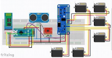
B. MicroBiPed Fritzing Diagram
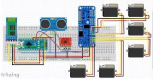
Fritzing diagram
This is the Fritzing Diagram provided by the E&C of previous semester. After choosing all of the necessary components, a fritzing diagram was created to map out the wiring before testing on a breadboard. The above components include: arduino, Bluetooth, gyroscope, ultrasonic sensor, and six servos. After successful testing on the breadboard, the message is relayed to the M&D division for printed circuit board designing.
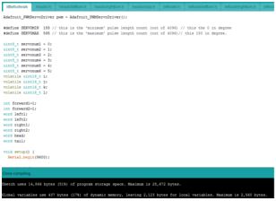
C. MicroBiPed Walking Code (C++)
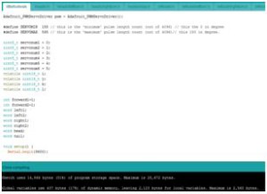
Walking libraries and coding in the Arduino software
Last semester, the data output type used was post width modulation (PWM) to control the servos.
The servo drivers were available on the website: https://github.com/adafruit/Adafruit-PWM-Servo-Driver-Library
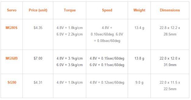
D. Servo Motors
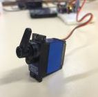
MicroBiPed servo
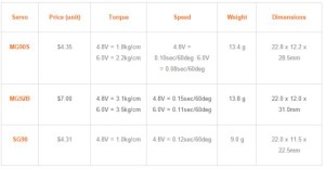
MicroBiPed servo trade-off study
The servo motors are responsible for converting electrical energy to mechanical energy, which will control the movement of the velociraptors head, tail, and two feet. Seeing the servos proved to be one of the most problematic issues of last semester, it is necessary to select one with a much larger torque. Comparing last to this semester’s servos, the JX PDI-6221MG provides 5x the torque of last years, but in addition also weighs 5x more. The trade-off are hefty, but the team plans to work around the cons of this vital component. Torque is a measure of “twisting force.” Servo specifications show that the units used are cm*kg. It can be calculated by using the cross product of force and distance, F = tau x d. With the torque specifications of the servo given, and the radius of rotation, a weight calculation can be made to see how much weight the servos can handle.
In order to address the concern of turning, two servos will be placed in each of the two legs in orthogonal planes to each other. The servos that rotate forward and backward will be for walking purposes, and the servos that rotate side to side are for turning.
In order to address the concern of balancing on an incline, two servos will be placed in each the head and tail in orthogonal planes to each other. The servos that rotate left and right will be for balancing (weight distribution) purposes while walking on a flat surface, and the servos that rotate up and down will be for balancing (weight distribution) purposes while walking up an incline.
Beginner-friendly video on the mechanics of servo motors:
https://www.youtube.com/watch?v=bu3SPwzcocU
Last semester’s servo:
http://www.headsuphobby.com/Towerpro-14g-MG92B-Digital-Metal-Gear-High-Torque-SubMicro-Servo-A-537.htm
Servo that the team is currently looking at for purchase (multiples of 4, x2, = 8 total):
http://www.banggood.com/4X-JX-PDI-6221MG-20KG-Large-Torque-Digital-Coreless-Servo-For-RC-Model-p-1031156.html
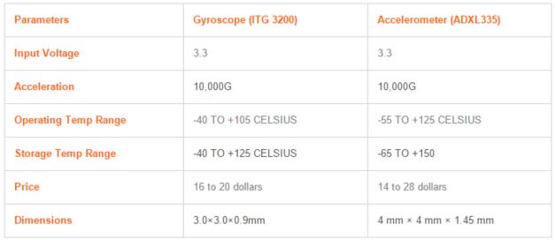
E. Accelerometer vs. Gyroscope
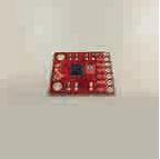
MicroBiPed gyroscope
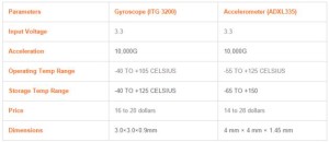
MicroBiPed motion sensor trade-off study
This sensor is important for the velociraptor in terms of control balancing. Each determines the position and orientation of the object. The accelerometer may be a better option for this semester’s velociraptor (the previous semester went with the gyroscope.) The accelerometer seems more practical since the gyroscope measures rate of rotation around a particular axis.
The difference between the two sensors:
http://www.livescience.com/40103-accelerometer-vs-gyroscope.html
Last semester’s motion sensor:
https://developer.mbed.org/cookbook/ITG-3200-Gyroscope
- Gyroscope: Uses the Earth’s gravity to determine orientation. It consists of a freely-rotating disk called a rotor, mounting onto a spinning axis in center of larger and more stable wheel. As the axis turns, the rotor remains stationary to indicate central gravitational pull, thus which was is “down.”
- Accelerometer: measures non-gravitational acceleration. When an object goes from zero to some velocity, this sensor responds to vibrations associated with movement using microscopic crystals that go under stress when vibration occurs. From that stress, a voltage is generated to create a reading on any acceleration.
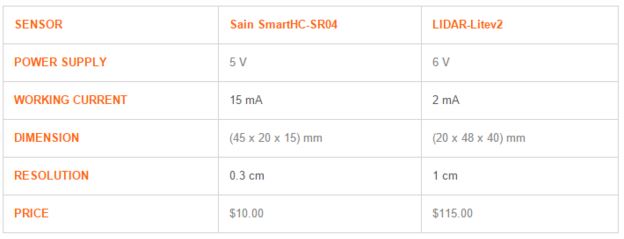
F. Ultrasonic Sensor
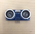
MicroBiPed Ultrasonic Sensor
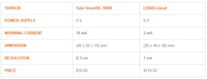
MicroBiPed distance sensor trade-off study
This component will be able to detect objects a certain distance away without contact. The MicroBiPed had the requirement of detecting a closeby object, and as a result, maneuver around the object by turning. The Sain Smart ultrasonic sensor of last year was able to provide a measuring function of 2 cm to 400 cm of no contact. The ranging accuracy of this component can reach to 3 mm. The velociraptor has quite a few feet before reaching its obstacle, so this distance sensor would be an exceptional pick for this semester as well.
Last semester’s ultrasonic sensor (HC-SR04): http://www.sainsmart.com/ultrasonic-ranging-detector-mod-hc-sr04-distance-sensor.html
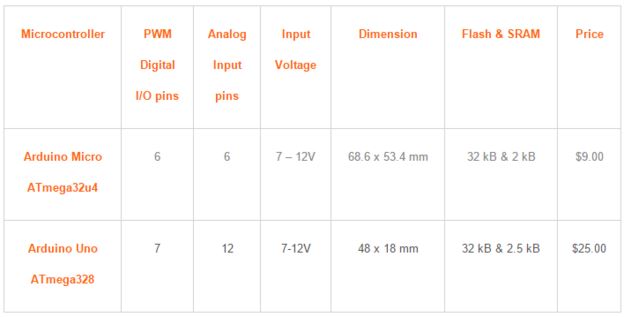
G. Microcontrollers
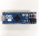
MicroBiPed microcontroller
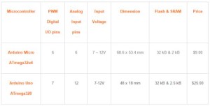
MicroBiPed microcontroller trade-off study
Last semester used the atmega32u4. A trade-off study was conducted last semester between this microcontroller and the 328p. The servos and ultrasonic sensor will need eight and two PWM I/O pins, respectively. However, the 32u4 and 328p only house six and seven I/O pins, respectively. No compensation was documented on how the MicroBiPed team overcame this issue.
Last semester’s microprocessor (Atmega32u4):
http://www.atmel.com/devices/atmega32u4.aspx
Atmega328p:
http://www.atmel.com/devices/atmega328p.aspx
H. Power Subsystem
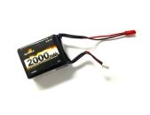
MicroBiPed battery
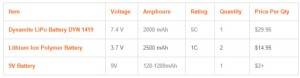
MicroBiPed battery trade-off study
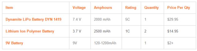
The battery will be the last component considered. After reviewing all of the actuator and sensor power requirements, the battery will be chosen accordingly. MicroBiPed team’s deciding factor for this component was the fact it was rechargable, making it cheaper for the customer in long-term usage.
Last semester’s battery:
http://www.advantagehobby.com/106601/DYN1419/74V-2000mAh-2S-5C-LiPo-Receiver-Pack-18/?utm_source=google+shopping&utm_medium=organic&utm_campaign=product&gclid=CJSascKm88oCFQ6maQodXAMEYw
Mingyu Seo (Manufacturing Engineer)
I. Source Material
(1) Microbiped Project Requirements, Project Level 1 Requirements, 09-18-2015
https://www.arxterra.com/microbiped-level-1-requirements/
(2) Microbiped Project Requirements, Preliminary Design Documentation, 09-24-2015
https://www.arxterra.com/fall-2015-microbiped-preliminary-design-documentaion/
(3) Microbiped Final Documentation, Mass Budget, 11-27-2015
https://www.arxterra.com/fall-2015-microbiped-mass-budget/
(4) Microbiped Final Documentation, Stress Analysis, 12-09-2015
https://www.arxterra.com/fall-2015-microbiped-stress-analysis/
(5) Microbiped Final Documentation, Center of Mass, 12-09-2015
https://www.arxterra.com/fall-2015-microbiped-center-of-mass/
(6) Microbiped Final Documentation, PCB layout, 12-09-2015
https://www.arxterra.com/fall-2015-microbiped-pcb/
(7)Microbiped Final Documentation, Prototypes, 12-16-2015
https://www.arxterra.com/fall-2015-microbiped-prototype-2/
II. Work Cited:
(1) Robot Simulator: Dinosaur-like Robot in V-REP. (n.d.). Retrieved February 11, 2016, from https://www.youtube.com/watch?v=-u4Y6tWfYRg
(2) Chilson, L. (2013, January 26). The Difference Between ABS and PLA for 3D Printing. Retrieved February 11, 2016, from http://www.protoparadigm.com/news-updates/the-difference-between-abs-and-pla-for-3d-printing/
(3) What material should I use for 3D printing? | 3D Printing for Beginners. (2015, February 23). Retrieved February 11, 2016, from http://3dprintingforbeginners.com/filamentprimer-2/
(4) 3D printing versus molding. Retrieved February 11, 2016, from http://arxterra.com/3-d-printing-versus-molding/
III. Literature Review:
Manufacturing and Design Review of previous Biped Projects. This will include overview of previous Manufacturing and Design engineer’s approach as well as planning (focus on topics related to the importance of WBS (Work Breakdown Structure), materials and simulations).
IV. Overview of Manufacturing and Design Responsibility:
- Create a prototype to test and validate subsystem commands provided by the Systems engineer.
- Create 3D models using ‘Solidworks’ to run statics and simulations to determine the acceptability of the design.
- Learn how to use CNC machines to fabricate components.
- Design and print PCB and perform ERC and DRC checks.
- Reflow soldering of the SMT discrete components and ICs onto the board.
- Specify and order off-the-shelf parts.
- Manufacturing will be responsible for full assembly of the Robot.
V. Note on WBS (Work Breakdown Structure):
The reason i have listed out the responsibility of the manufacturing engineer was to emphasize the importance of WBS (Work Breakdown Structure). Most of the blogs posted by previous microbiped had all engineers working on different research as well as tasks throughout the semester. The WBS not only assigns each engineer with specific tasks but also it helps the project manager to maintain and organize all procedure of the project. By simply looking at the dates of the blog posts, mass budget, stress analysis, Center of mass, PCB layout, and prototype was built and tested almost toward the end of the semester. According to microbiped level 2 requirement, the robot must be tested by December 10th 2015, but the 1st generation was tested on november 19th 2015. Due to limited time, the team was unable to run enough simulations using prototypes. The main problem was insufficient time to fix the robot which led to problems that will be defined below.
The three major problems that relate to the responsibility of the manufacturing engineer included size, weight and the joints of the robot.
VI. Size & Weight:
Previous generation components were made into solid parts which made the size of the robot exceed the project level 1 requirement, to be considered a miniaturized Biped Robot, exceeding the max height of (120mm). Solution to this problem was to create hollow parts rather than solid, and also in order to minimize the weight load on the body, we will be distributing our battery toward the head and the tail to evenly distribute and decrease the weight of the total robot.
VII. Joints:
Previous generation’s joints was unable to withstand the weight of the body, which led to the head and the tail not turning fast enough, and making the weight of the head and tail be held by the servos.In order to solve this problem, we will be designing a lever arm to allow the head and tail to move faster with the same torque, and design a new fram to hold the head and distribute the weight to the body, leaving the servos to only push the lever arms. Most importantly, we will be creating a 3rd joint to keep the legs more stable during static and dynamic walking as well as supporting the joints to hold up the weight of the body.
Velociraptor Solidwork prototype leg
VIII. Materials: (Prototype)
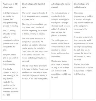
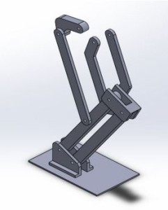
As a manufacturing engineer, the main task is to create a 3D model on Solidworks to run static simulations to determine the acceptability of the design. Through simulations, it will help us to determine the appropriate material that can withstand the weight of the body. Although running a simulation could determine the practical use of the material, it is crucial to print/mold components for our robot to actually run simulations for other possible problems. By looking at the chart below, we could compare the advantages and disadvantages between 3D printers and molding methods.
The previous generation created prototypes using molding method and wooden planks to build the joints for the robot. Although molding the joints could be a plausible material in building prototype due to the material’s strong resistance in heat as well as durability to withstand the weight of the body, it is very time consuming to create a mold and extremely hard reprinting the part. Prototypes should be built in a short amount of time with malleable materials such as plastic, wood or metal in order to easily customize and fix when a problem occurs. Through comparing 3D printing and molding, our team has decided to use the 3D printer for our first prototype. CNC machine has been excluded from our prototype material due to expensive printing costs and inability to make changes after.
3D printing versus molding method
The most optimal material that will be used for 3D printing is a Polylactic Acid (PLA) plastic, which is derived from renewable resources, such a cornstarch, sugarcane, tapioca roots or even potato starch. PLAs are widely used among home printers, hobbyists, and school making it easily accessible all through the semester. 3D printing parts are much quicker to produce, and allows the users to customize. One of the advantages of using a PLA is due to low melting point (50 ~ 60 degrees Celsius) of the material, we will be able to re-heat our printed components using hot air gun, for example, to modify the shapes to easily repair the components.
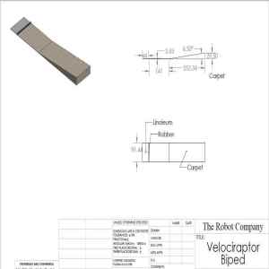
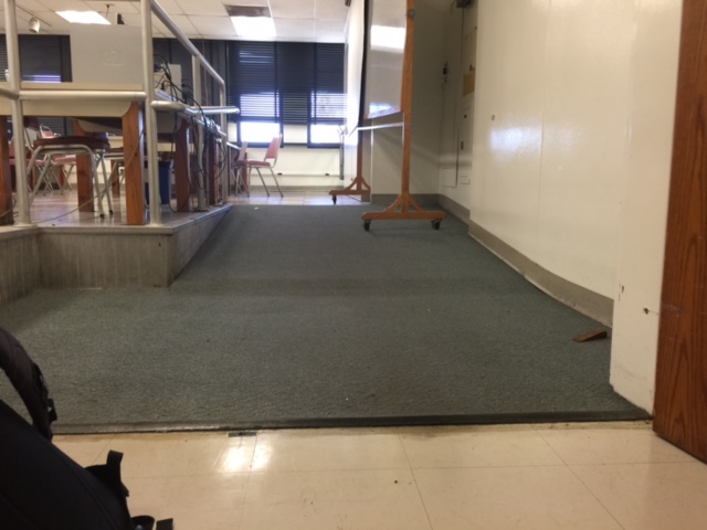

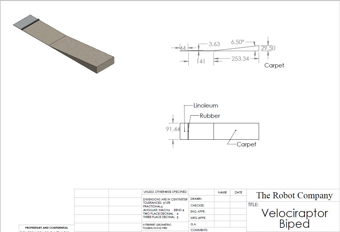
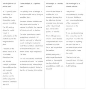
 Figure 4: Berber Carpet