Velociraptor Team:
Jesus Enriquez (Project Manager)
Oscar Ramirez (Mission, Systems, & Test)
Mohammar Mairena (Electronics & Control)
Andrea Lamore (Manufacturing)
Program Objective/Mission Profile
By Jesus Enriquez (Project Manager)
The Velociraptor Biped, inspired by that of the Titrus-III model developed by the Tokyo Institute of Technology, is to meet customer expectation through demonstration in a negotiated battle defined between the customer and the Robot Company project teams. While carrying out the mission, the Velociraptor will be operated through video support from a remote location using an assigned support vehicle from The Robot Company. The Velociraptor will be further controlled by a designated user through the Arxterra mobile application.
References:
EE 400D S’17 Project Objectives and Mission Profiles
Requirements and Verification
Program/Project: Level 1 Requirements
By Jesus Enriquez (Project Manager)
- The velociraptor budget shall not exceed an estimated cost based on an agreement between the customer and the project team
- The Velociraptor Biped Robot shall demonstrate that it has met the capabilities expected from the customer during the EE 400D Final on May 15th, 2017
- The Velociraptor should resemble a Velociraptor of the Theropodous Dinosaur Suborder
- The Velociraptor will use a 3DoT board embedded system
- The Velociraptor will use the Arxterra Android or iPhone Application and/or control panel to control the Velociraptor
- The Velociraptor shall operate with an external power source for a minimum time based on an agreement between the customer and project team regarding the mission objective
- The velociraptor shall use an external PCB with an I2C interface as the 3DoT board
- The Velociraptor shall use a 3DoT board while using I2C to communicate with electronic sensors, A/D converters, and GPIO
- The Velociraptor with its support vehicle shall have no more than one top secret weapon, approved by the management team
References:
Fall 2016 Velociraptor (Th): Preliminary Design Document
Spring 2016 Velociraptor: Preliminary Design Document
System/Subsystem: Level 2 Requirements
Mission, Systems, & Test
By Oscar Ramirez (MST)
- The Velociraptor Biped Robot shall use a 3DoT board as a servo motor driver and main microcontroller unit on the Biped
- The 3DoT board shall also work alongside the main PCB board and other on board sensors, drivers, and the Bluetooth communication system
- The Bluetooth communication system on the Velociraptor Biped shall be used to sync the user’s Android/iPhone device
- The user shall communicate with the Velociraptor Biped Robot via the Arxterra Android/ iPhone application to perform all the required tasks
- The power source shall be able to fit inside or on the robot and must be integrated into the Velociraptor Biped such that it does not affect the functionality of the robot
- The Velociraptor Biped’s 3DoT board shall use the appropriate libraries to communicate with the accelerometer, A/D converter, servo motors, and all other components on the PCB
- The Velociraptor Biped testing shall be conducted twenty-five feet from the robot and via a live feed to simulate the challenge conditions that are TBD
Electronics & Control
By Mohammar Mairena (E&C)
- The external battery should last for up to one hour
- The robot shall equip the right amount of torque to bear the weight of the Velociraptor
- The Velociraptor will use one DC motor for each leg
- The Velociraptor should use rotary encoders/sensors
- The Velociraptor will use one servo motor for the head and one servo motor for the tail to work independently of each other
Manufacturing
By Andrea Lamore (Manufacturing)
- The structure of the Velociraptor shall be made of Aluminum and/or 3D printed material
- The feet of the Velociraptor will be padded with rubber soles
- There will be a total of TBD motors within the body of the Velociraptor
- The Velociraptor shall be capable of calculating its center of gravity dependent on the position of its motors allowing it to adjust itself
- The Velociraptor will use servos and motors capable of supporting the body with the legs
- The Velociraptor shall be capable of achieving a static walk
References:
https://www.arxterra.com/fall-2016-velociraptor-preliminary-design-documentation/ https://www.arxterra.com/3dot
https://www.arxterra.com/fall-2016-velociraptor-th-preliminary-design document/#Electronics_Subsystem_Requirements
Design Innovation
By Jesus Enriquez (Project Manager)
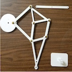
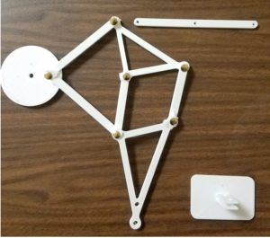
After researching through the different designs of the previous generations of Velociraptor Biped Robots, it was noted that the certain types of leg mechanisms such as the Theo Jansen linkage was not appropriate to get the Robot to walk in a dynamic fashion but rather a static motion since it can only move forward and backwards rotating along a single axis. This limits the robot in terms of flexibility to move and turn in a dynamic fashion. Considering the mission of this robot per the customer’s request, it is essential that the robot have flexibility in its ability to move and turn under certain conditions. Using the creative process, our group was able to generate a few solutions.
Creativity Presentation
System/Subsystem Design
Product Breakdown Structure
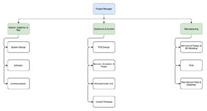
By Oscar Ramirez (MST)
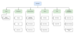
Power
The Velociraptor Biped will be powered by a portable power source that while not taking away any functionality or balance to the Biped must also be able to power the robot.
Body
The frame of the robot must have a strong material considering it will have a higher center mass when walking dynamically. The frame will consist of the head, tail, legs, and chassis. Aluminum will be ideal for this since it is not only a strong but lightweight material. Aside from the physical advantages to using aluminum the cost will also benefit the design since aluminum is going for about $30 per 4 square feet at 1.6mm thickness. This translates to a little more than one and a half kilograms of aluminum but not all of the 4 square feet sheet will be used and the frame of the robot will likely be the bulk of the mass.
Sensors and Drivers
An accelerometer will be used to help while walking to track motion and ensure that the system is not off balance. An analog to digital converter will also be used with the DC motors to track the position of the motors rotation and translate it into digital data that will be read into our microcontroller. Drivers will also be used for the DC motors since the microcontroller cannot directly control the speed of the motors.
Motors
As required by the customer, DC motor will be incorporated into our design. There will be two total DC motors that will provide motion to our Velociraptors legs and carry the majority of this load. Servo motors were used in the past but DC motors are better suited for the task since the can handle more torque. Servo motors will still be used in our design but they will be restricted to controlling the head and tail to move in sync with the center mass of the robot. Stepper motors will also be used to help provide more stability and needed torque for the legs.
PCB
There will be two PCB boards incorporated in our design. One of them will be our 3DoT board that will contain our microcontroller and control the servo motors and the other will be the main PCB board that will have all other sensors, communications systems, and drivers.
Software and Communication
The Velociraptors software will be based in C++ and written in an Arduino sketch. This sketch will control all motor functions and communicate to the Bluetooth module. The Bluetooth module will then sync with the users Android or iOS device and be controlled via the Arxterra control panel application. This application will have a GUI that will let the user perform any function of the robot such as walking, turning, and use of the on board secret weapon.
References:
http://arxterra.com/fall-2016-velociraptor-preliminary-design-documentation/
https://www.metalsdepot.com/products/alum2.phtml?page=sheet
https://www.arduino.cc/
https://www.arduino.cc/en/Main/ArduinoMotorShieldR3
Electronic System Design
System Block Diagram
By Mohammar Mairena (Electronics & Control)
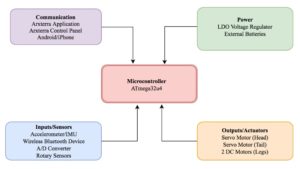
Shown above is the block diagram for the electronic design. Within the 3DoT board is the I2C interface that allows the user to add multiple devices using the SDA and SCL pins (data and clock, respectively). The block diagram highlights the importance of the micro-controller as the root of each and every device as well as the significance of the micro-controller in terms of communicating with certain devices.
Interface Definitions
By Jesus Enriquez (Project Manager)
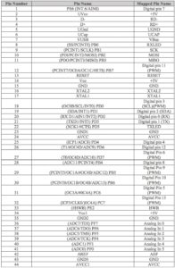
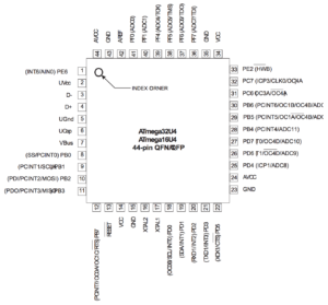
Reference:
https://www.arduino.cc/en/Hacking/PinMapping32u4
Mechanical Design
By Andrea Lamore (Manufacturing)
The velociraptor design be broken down in the following: The legs, feet, and the head-tail.
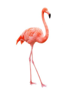
The entire design is going to be top-heavy and tall. Making the device top heavy will allow for good traction to floor and a small moment of inertia at the body so the top (the body) is more stable than the legs. The tall height in the legs makes it so there is a longer radius between the body and the feet, this also increases the moment of inertia at the body. A longer radius will give the robot more time to catch itself.
Leg Structure
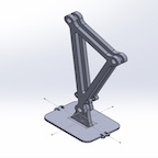
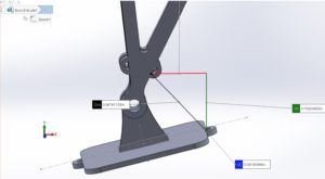
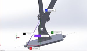
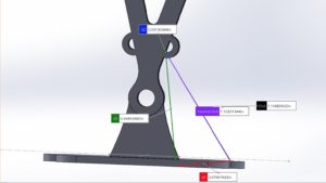
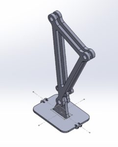
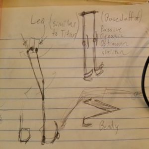
The leg’s structure is going resemble that of a robot’s that is able to complete a passive dynamic walk. Without a mechanical control for preventing “bounce back” in the knee (referring to the knee bouncing back to bent after straightening), the leg design will not be able to complete a passive dynamic walk. Instead of a mechanical mechanism to prevent bounce back, there will be two motors used to control each leg – like the Titrus III design. One motor is responsible for the knee motion and the other for the swing of the hip. Using a combination of the successful passive walking robot and the Titrus III model, we will be able to create a leg that has the physical structure required for both passive and dynamic walking.
Static Walk
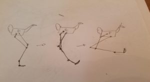
For the static walk the legs will be crouched by bending the knee and rotating the hip. This crouch will lower the center of mass and make the robot’s stance more stable. In the crouched position, the robot will utilize its head and tail to shift the center of mass from side to side depending on the foot that is stepping. In the crouched position the knees will move forward and the robots center of mass will be shifted, the upward motion of the head will be used to compensate for that forward motion. The tail will be capable of being used as a third leg so that the robot may utilize a very stable tripod stance.
Turning
Turning will be controlled by motor as the hips. The motors responsible for turning will be placed here in order to keep the top heavy and reduce bulk in the legs so that the legs may accelerate as fast as possible and thus catch the robot as it falls on each step faster. The hips, if viewed from the top will angle the leg away or towards being in parallel with the other leg.
Feet
The feet will be statically joined at the ankle in order to reduce the amount of motors needed. If the legs need not enter the crouching position then the static flat foot with the heal attached to the ankle would suffice, however, since the robot will be crouching, the foot will need to roll over onto a different plane in order to keep the robot stable. To solve the problem, the robot will be able to bend its leg backwards (in the opposite direction of the dynamic walk bend) and roll over onto the ankle plane which will be at a slightly different angle from the rest of the lower leg.
Head/Tail
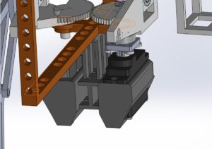
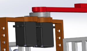
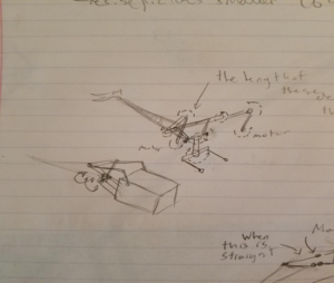
The head and the tail will move up & down and side to side. This mechanism will be that of the Titrus III robot, which used a “horse reign” schematic to control the head and tail. This “horse reign” method is similar to the reign of a horse in that two motors control the head/tail to move wither side to side or up and down. When one of the motor is rotated the head will turn either away or toward the motor in motion by moving left to right. If both motors are rotated in the same direction the head/tail will either lift or fall to the ground.
References:
https://www.youtube.com/watch?v=rhu2xNIpgDE&list=LLNnlTvhtytEM7T9W2Ou5IGA&index=27
https://www.youtube.com/watch?v=GxVv4WNlXMA&index=29&list=LLNnlTvhtytEM7T9W2Ou5IGA
Design & Unique Task Descriptions
Electronics & Control
By Mohammar Mairena (E&C)
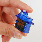
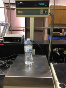
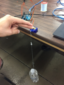
The battery used to power the Velociraptor must take into account a few things such as: current capacity and mass of the battery with relation to the robot’s total weight. In order to choose the right battery in accordance to its specifications, tests must be run. The Servo motor will be under different load conditions and we will record measurements for current drawn in each unique load condition. Additionally, the operating voltage for DC and Servo motors will be 5V.
Velociraptor Electronics & Control Tasks
- Perform a servo test to determine the servo load vs the current drawn with respect to the load
- Conduct trade off study to determine which DC motor best serves 3DoT board
- Conduct trade off study to determine which Servo motor best serves 3DoT board
- Create a fritzing diagram to test the breadboard
- Create an electrical schematic/PCB based on Eagle CAD
- Determine the total current drawn in order to pick the correct battery for the robot
- Conduct control algorithm tests for Servo motors through Arduino IDE
- Conduct control algorithm tests for DC motors through Arduino IDE


