PCB Fabrication

Author: Diane Kim (Division Manager of E&C Hardware)

Verified By: Jordan Smallwood (Project Manager)

Approved By: Miguel Garcia (Quality Assurance)


Table of Contents

Introduction

To fabricate our board, we use a PCB fabrication machine called the V-One from Voltera. Its function includes printing, soldering, and drilling.

Printing

V-One uses conductive ink to print the traces of the circuit. It will print the traces and bake it as well. The limits of the traces are:

  • Minimum 8 mil trace width and spacing
  • Minimum 0.65 mm pin pitch for SMT components
  • Minimum 0603 passive size
  • Minimum circuit size 1 x1 mm

Soldering

After the trace is done, the V-One can print the solder paste onto the desired traces. The user must manually place the pieces onto the board. After the pieces are place, the V-One will bake the board once more to heat up the solder paste. The limitations of soldering are:

  • Minimum 0.5 mm pin pitch for SMT components
  • Minimum 0402 passive size

Drilling

The V-One can also drill holes through the circuit board. The drill sizes are 0.7, 0.8, 0.9, 1.0, 1.6 mm for the diameter. Therefore, the smallest hole size is 0.7 mm which is 27.6 mil. To connect the top and bottom layer, rivets are used, and the given rivet sizes are 0.4 mm and 1.0 mm for the inside diameter.


Software

To communicate between Eagle CAD and the V-One, Gerber files are used. V-One has its own CAM processor that outputs the top, bottom, solder paste and drill layers. Once the Gerber files are converted from the Eagle CAD, it is uploaded into the Voltera software which allows the user to choose the desired action: print, solder, bake, or drill. Each process has its own procedure which the user can follow easily with the guidelines that are shown through the process on the right side of the window.


Procedure to Fabricate the Board

Drilling:

Drilling is done first. The board is placed onto the pad and then the drill size is chosen. For our board, we are using the 0.7 mm and the 1.6 mm drills.

Figure 1. Picture of the drill in action

Printing:

After the drilling is done, the top layer is printed first. The board is not moved therefore the previous alignment can be used. After the conductive ink is printed, the board is heated to bake the conductive ink.

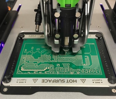
Figure 2: printing process

After the top layer is baked, the board is flipped to print the bottom layer. Since the board is moved, alignment is needed so that the top and bottom match. After the alignment is done the bottom layer is printed and baked.

Connecting Top and Bottom Layers:

The top and bottom layer are connecting using the rivets. The flat side of the rivets are placed into the through-holes connecting the top and bottom. To flatten the non-flat side of the rivets, the rivets pressing tool is used. After each rivet is pressed, the multimeter was used to confirm that there is a connection between the top and bottom pads.

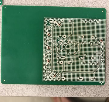
Figure 3: Rivets done

Cutting the Board

We needed to cut the board because the machine doesn’t have the function to do so. Therefore, we used the machines given access to mechanical engineering majors to do so.

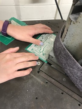
Figure 4: Cutting the excess part of the board

Soldering:

Alignment is needed once again since the board is moved so that the location of the pads is known to the machine. The solder paste is printed on the pads and the components are placed onto the correct locations and baked once more.

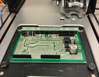
Figure 5. Picture of the soldering

After the surface-mount component is placed, the through hole components. For our board, we had male and female connectors that needed to be hand soldered. Following the guide form the soldering workshop blog post, the connectors were hand soldered

Final Testing:

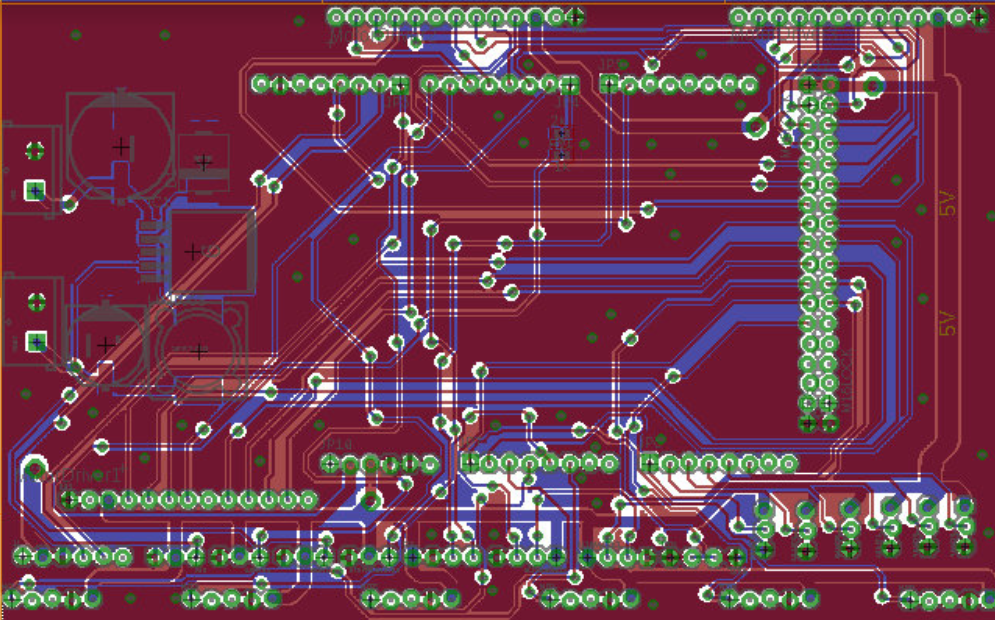
The final product is shown below and the connections were checked using a multimeter. Basing off the interface matrix, the connection between the peripheral systems pinout and the ATmega2560 pinout was checked. All the connections were checked.

Figure 6: Final Project

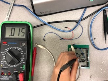
Figure 7. Testing the connection of the traces


Conclusion

The time taken to fabricate the PCB was 7 hours. It took two hours to draw the traces for each side, one hour to bake the traces, and another hour to solder on everything. When it came to testing the board, we weren’t able to due to technical problems. We were able to connect all the components onto the circuit board and the ATmega256. However, during the process, the board got shorted and damaged the board. We didn’t have enough time nor material to print out the board, therefore, we weren’t able to print out another one.

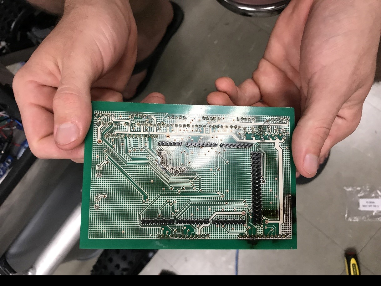
Figure 8: Image of the damaged board

Solar Panel Charging

By: Mohammad Yakoub (Mission, Systems, and Testing)

Verified By: Jordan Smallwood (Project Manager)

Approved By: Miguel Garcia (Quality Assurance)


Table of Contents

Introduction

The objective of this blog post to find a way to charge the main battery with the solar panel cells. There are different ways to go about this, but I found that the best way for our project is to use a charge controller. This way we can make sure that we do not overcharge the battery with our solar panel.

The specific charger we are using is called The xcsource Solar charge Controller. This specific one is purchased from amazon.

Figure 1: Top View of Charge Controller

A charge controller is basically a voltage/current regulator to keep batteries from overcharging. It regulates the voltage and current coming from the solar panel going to the battery. Most solar Panels supply more voltage than rated, because these panels need ideal conditions to be able to provide full power, and those conditions are impossible to meet. The panels are designed to provide power than rated, so it can still function in less than ideal conditions. So without regulating the solar panel The battery can be damaged from overcharging.


How it Works

The way that works is we connect the solar panel and the battery to the charge controller. The charge controller will charge the battery and power our components. The charge controller will charge the battery until the it reaches a full charge and as the battery charge gets higher the controller will reduce the solar panel output to avoid overcharging the batteries. Once the battery is nearly full, the charge controller only sends a trickle charge to top off the batteries without overcharging them. This process is known as the off grid charging. An alternative process is to allow the solar panel to supply power to our components directly, but that is not as efficient, and will not be able to supply enough energy for the motors. When the battery reaches a full charge the controller will switch the power output of the solar panels to a dedicated load, such as a light or heating filament.

Figure 2: Typical connection of Solar Panel – Battery Controller


Conclusion

As mentioned earlier the charge controller is mainly used to prevent overcharge, and improving charge quality. But that is not the only advantage of using the charge controller, it can also prevent battery discharge in low or no-light conditions. Discharging can happen when the sunlight goes out the battery will discharge to heat the solar panels. However, the charge controller will detect the batteries discharging and disconnect the panels, to prevent the discharging of the battery. This can also be achieved by using solar panels with blocking diodes that prevent battery discharge during low or no-light conditions, but such systems are not as efficient when using high power solar panels.


References

  1. https://www.batterystuff.com/kb/articles/solar-articles/solar-info.html
  2.  https://www.amazon.com/Controller-Charge-Battery-Regulator-Protection/dp/B010FNO9NU/ref=sr_1_3?ie=UTF8&qid=1525723142&sr=8-3&keywords=solar+controller+10a
  3. https://www.aliexpress.com/item/10A-CMP12-12V-24V-intelligence-Solar-cells-Panel-Battery-Charge-Controller-Regulators/619325690.html?src=google&albslr=119861048&isdl=y&aff_short_key=UneMJZVf&source=%7Bifdyn:dyn%7D%7Bifpla:pla%7D%7Bifdbm:DBM&albch=DID%7D&src=google&albch=shopping&acnt=708-803-3821&isdl=y&albcp=653153647&albag=34728528644&slnk=&trgt=61865531738&plac=&crea=en619325690&netw=s&device=c&mtctp=&aff_platform=google&gclid=Cj0KCQjwodrXBRCzARIsAIU59TK4xse4VJUY-AmA0KTMhI5Mr_pqDeCrQ-Z9OL_oY1lKCcZHztYFMXEaAlqtEALw_wcB&gclsrc=aw.ds
  4. http://uisalumnisage.org/solar-light-wiring-diagram-2/for-solar-light-wiring-diagram/

Stepper Motor Study

By: Adolfo Jimenez (Manufacturing)

Verified By: Jordan Smallwood (Project Manager)

Approved By: Miguel Garcia (Quality Assurance)


Table of Contents

Introduction

In order to test the articulation of the solar panels before they were assembled onto the chassis an EasyDriver stepper motor driver was used to run and test the motors, and thus by extension the solar panels. Stepper motors can move an exact amount of degrees (or steps) when programmed to do so. This gives us total control over the motor, allowing us to move it to an exact location and hold that position. This is done by alternating power sent to 2 separate coils inside the motor at fractions of a second. A stepper motor combined with a motor driver and microcontroller allows us to dictate the speed and amount of steps taken in any direction making them ideal for our solar panel articulation system.


Parts Used

  • Bipolar Stepper Motor (ROB-09238)
  • EasyDriver – Stepper Motor Driver (ROB-12779)
  • Arduino UNO
  • Breadboard, Wires, 10k Resistor (x2), 12V Power supply

Figure 1: Typical Stepper Motor

Figure 2: Sparkfun Easy Driver


Assembly

First, the board needed to be assembled, that was a quick and easy job requiring the soldering of the 17 included header pins onto the board. The next step was wiring the entire setup, to do this we first needed to identify which of the four wires pertained to each coil wire pair within the motor. Looking at the datasheet for this stepper motor we can see that the red and green wires form one coil, while the yellow and blue form another. To test this, an LED can be connected to a wire pair on each lead. If the LED blinks while manually turning the motor shaft then those two cables indeed form a coil. The first coil pair should be plugged into Coil A+ and Coil A-, while the second coil pair plugs into Coil B+ and Coil B-. After further research it was discovered that there is no polarity on the coils, so you need not worry about plugging in a coil backwards onto the board. As per the specifications on the datasheet for the motor, a 12-volt power supply was selected to power the motor. All remaining connections can be seen in the following fritzing diagram:

Figure 3: Fritzing Diagram for Simple Stepper Motor Operation


Code

With the physical circuit built the following code was uploaded onto the Arduino UNO to begin controlling the motor. When the code is running, it waits for a button press (a LOW on Arduino pin 2 or 3) and then begins to rotate the stepper motor for the programmed number of steps. A push button switch was added between Pins 2, 3, and ground, with an accompanying 10K pull up resistor used for each pin at 3.3V. For this set up, pin 3 associated with the button on the left (LOW on pin 3) turned the motor clock wise, the button on the right (LOW on pin 2) rotated the motor counter-clockwise.

Figure 4: Code for Simple Operation of Stepper Motors


Conclusion

Utilizing this described setup I was able to test the stepper motors and begin working on the solar panel articulation for our rover. Messing with the code I found that using the motor at slower speeds appeared to provide me with more torque as spinning it at a slower RPM provided the greatest resistance against pressure applied on the shaft by squeezing it with my fingers. One thing to really note is the current adjustment potentiometer on the EasyDriver. I recommend that while the code is running, with a small screw driver slowly turn the potentiometer one way or the other. Depending on the type of motor you use (mainly its coil resistance) you may notice a difference as different current values might operate the motor much more smoothly than others.


References

  1. https://www.sparkfun.com/datasheets/Robotics/SM-42BYG011-25.pdf
  2. http://www.schmalzhaus.com/EasyDriver/Examples/EasyDriverExamples.html
  3. https://www.sparkfun.com/tutorials/400
  4. https://learn.sparkfun.com/tutorials/easy-driver-hook-up-guide?_ga=2.95969304.586601746.1525205163-1420080731.1522797085

Custom PCB for Solar Panels

Author: Diane Kim (Division Manager of E&C Hardware)

Verified By: Jordan Smallwood (Project Manager)

Approved By: Miguel Garcia (Quality Assurance)


Table of Contents

Introduction

The second PCB is for the solar panels which consists of the connection for the stepper motor drivers (3), current sensors (6), and GPIO expander. We are using the stepper motor from Sparkfun therefore we decided to go with the stepper motor driver associated with it—the EasyDriver. Although we wanted to implement the circuit itself, the IC that is used for the EasyDriver was not available, therefore we are going with the shield. To decrease the pins from the EasyDriver to the ATmega2560, we are using the I2C bus for the EasyDriver and the current sensors.


Stepper Motor Driver Connection

The connection from the EasyDriver to the ATmeag2560 are the MS1, MS2, DIR, ENABLE, and STEP. The Eagle file for the EasyDriver schematic can be found on Sparkfun’s website. The 3 stepper motor drivers are placed side-by-side horizontally.

Figure 1: Placement of the Stepper Motor Driver

Figure 2: Placement of Motor Drivers on Solar PCB

  • MS1 and MS2

MS stands for micro-step and is used to determine the resolution of the step. For our specific design, we will be setting both MS1 and MS2 to ground or both to low since we don’t need high resolution to fold and unfold the solar panels.

Figure 3: Truth Table of MS1 and MS2 Resolution

  • DIR & ENABLE

The DIR pin is a logic input that determines the direction of the stepper motor. The ENABLE pin is a logic input that determines whether the IC drives the motor. These two inputs will connect with the Atmega2560 by the I2C bus.

  • STEP

STEP is a logic input that is triggered when the pin goes from high to low. The STEP is connected between all three motor drivers since they will all be operating at the same time.


I2C Bus

I2C connection uses the two connections SDA and SCL to connect between the master and the slaves. If we didn’t go with the I2C connection, we would have needed 7 wires from the stepper motor driver to the ATmeaga2560. By using the GPIO expander, we connect DIR and ENABLE for all 3 stepper motor driver to SCL and SDA. For our circuit, we are using the TCA9534APWR chip from Texas Instruments. Each I2C bus needs a pull-up resistor for both SDA and SCL. In addition to the SDA and SCL from the GPIO expander, we are adding the SDA and SCL from the current sensors to the I2C bus. We are using the 1NA3221 Breakout Board from Switch Doc which has four programmable addresses.

Figure 4: I2C Bus connection of Stepper Motor (DIR and ENABLE) and Current Sensors)


Final Version of the PCB

Figure 5: Final Version of PCB with Copper Ground and Power Planes

Figure 6: Final Version of PCB without Copper Ground and Power Planes


Conclusion:

The Solar Panel PCB was never tested due to the solar panel mechanism never being completed.


References

  1. Eagle File: https://drive.google.com/open?id=1-hPQAabUNwHn-SUBNcfJ6V6lTwZHwjUo under SolarPanelShield.brd and .sch
  2. I2C Bus: https://learn.sparkfun.com/tutorials/i2c
  3. Stepper Driver: https://www.sparkfun.com/products/12779

Custom Chassis PCB

Author: Diane Kim (Division Manager of E&C Hardware)

Verified By: Jordan Smallwood (Project Manager)

Approved By: Miguel Garcia (Quality Assurance)


Table of Contents

Introduction

Unlike many of the other projects that are required to use the 3DoT board, we will be using the ATMega 2560 due to a large amount of connections. Since many of the interconnections are from pin to pin, specifically the motor drivers, we have made a custom shield to route many of these signals. 

Table 1: Side view of the Design for the Custom Circuit


Aside from the connections to the peripheral devices that are mentioned above, the custom PCB for the chassis has the buck converter that will convert the 12v from the battery to 5v to supply power to the ATmega2560.


Design of the PCB

Buck Converter

Through a different experiment, we confirmed that we will be using the LM2596 buck converter. Since we will be converting between a fixed voltage of 12v to 5v, we are using the fixed output design from the datasheet.

Figure 1: Typical Schematic of the Fixed Output Buck Converter

Based on the datasheet, the Cin , Cout, and inductor value was determined. The capacitors also have to be low-ESR or impedance for the circuit. The traces that are drawn with bolded lines must be kept short and thick for better results.

  • Cin: 470uF/35v
  • Cout: 220uF/25v
  • Inductor: 68uH/3.10A

Figure 2: Eagle Schematic of the LM2596

Connection for the Motor Driver

Figure 3: Dimension of Pololu dual VNH5019 motor drive

We are using the Pololu dual VNH5019 motor driver for the Pathfinder. Since we are limited to a 5×4 cm (WxL) board, due to limitation’s of the PCB fabrication machine we are using, we have decided to place the connectors so that the board doesn’t exceed the maximum size. The drivers are placed vertically so that the width of the PCB doesn’t exceed 5 cm.

Figure 4: The Overview of how the motor drivers are placed The black outline is the line of dimension of the shield so that it doesn’t exceed 5 cm.

Connection’s of the other peripheral systems

We initially thought about making the HM-10 Bluetooth module a part of our PCB circuit, but we instead decided to use the breakout board and use connectors. Since the RX of the Arduino can only take in 3.3v and the TX of the HM-10 outputs 5v a voltage divider was used. To get 3.3v from 5v, we used 1k and 2k resistors.

Figure 5: Level shift resistor for the HM-10 connection to RX of Arduino Mega

  • The current sensors are used to measure the amount of current from the motors. Although there are current sensors in the motors, the lower limit of the amount of
    current is not low enough for our no-load protocol. Therefore these current sensors will be connected to the motor drivers and the motor’s pin for the current will be routed through these current sensors. We used the Adafruit INA169 DC current sensor breakout board.
  • Other peripheral devices are the ones mentioned above: motor drivers (3), shaft encoders for the motors (6), ultrasonic sensors (2), servo motors (2), LEDs (2), fan, HM-10 (Bluetooth), current sensors (6), and stepper motor drivers (3). The connection is based on the interface matrix. The connectors are placed on the outer part of the shield so that the motor drivers do not cover the connections.

Final Version of PCB

Figure 6: Eagle File for Final Chassis PCB with ground pour

Figure 7: Final Chassis PCB without Ground Pour


The board was very simple to design since it essentially connected all the systems together, however, there were some considerations that needed to be accounted for. The size of the board was restricted to 4″ by 5″ due to the fabrication machine used. Since the motor drivers had to be placed horizontally and the board was a shield for the ATmega2560, the positions of the connectors were fixed and some of the traces had more resistance than the shorter wires. In addition, the ground and the power
planes needed to be laid out so that there is a good connection. This means that ground vias were added and the trace for the power was thicker than the traces for transmitting data. Another problem that arose was the connection between the pads and the connectors. The connectors did have a connection but it was easily disconnected if a small force was applied to it.


References

  1. EAGLE File: https://drive.google.com/open?id=1-hPQAabUNwHn-SUBNcfJ6V6lTwZHwjUo under MotorDriverShield_aaproved.brd and .sch
  2. Buck Converter: http://www.ti.com/product/LM2596
  3. Motor Driver: https://www.pololu.com/product/2502

Motor-Mock Up

By: Jordan Smallwood (Project Manager)

Approved by: Miguel Garcia (Quality Assurance)


Table of Contents

Introduction

One of the requirements of the Pathfinder is to determine whether a no-load condition is present, we needed to define what that condition is. In order to test the characteristics of our motor a simple experiment was conducted. The idea is that we wanted to control the load to the motor under a constant voltage and extract the current from the Arduino.


Setup

Appropriate connections were made to interface the Arduino to the VHN 5019 motor drivers so that we could read the output voltage from the onboard current sensors. To communicate with the Arduino through MATLAB we needed to install an add-on package called, “MATLAB support package for Arduino Hardware”. This add-on is very simple to use and eliminates the need for uploading code through the Arduino IDE. It allows for direct control of the Arduino through the serial port and MATLAB has predefined functions that allow for this.


Software

Figure 1: Code for Plotting Motor Current Draw

The code is very simple, it is a while loop that compares the current time with the limited time. While in the loop it reads the analog voltage from the current sensor and then stores that value in a vector that has a corresponding time stamp. After this you can apply some smoothing features to the plot such as an n-point moving average so that we don’t see all the discontinuities.


Results

Figure 2: Results from Motor Mock Up


After applying a 25 point moving average this is the result. I applied a resistance to the wheel with my hand about every 5 seconds or so and as you can see, the spikes are where the load was applied. This is very good information for us since we know that the motor under no-load is about 30 mA. In addition, these motor’s have much less current draw than the previous motors on the Pathfinder. In order to get accurate results when applying this to the final mission, we will need to apply an averaging filter to ensure we don’t turn off the motors when they are actually experiencing a load.


References

  1. https://www.mathworks.com/videos/plotting-live-data-of-a-temperature-sensor-using-arduino-and-matlab-121317.html
  2. https://www.mathworks.com/hardware-support/arduino-matlab.html
  3. https://www.pololu.com/product/2502

No-Load ISR

By: Jordan Smallwood (Pathfinder Project Manager and Electronics & Control)

Approved By: Miguel Garcia (Quality Assurance)


Table of Contents

Introduction:

The idea is that if any of our motors are under a no-load condition we want to cease power to that motor, since it makes no sense to waste power on a freely spinning motor. In order to do this we will need to understand the conditions present when our motor is experiencing no-load. This is determined in the motor-mock up study found HERE. Since current is proportional to the load that the motor is experiencing we can check the current to each motor and compare with the conditions. This will be implemented with an internal timer interrupt.

The robot will not be travelling that fast and we can set a timer interrupt with a period of 100 ms that will check the motor conditions every 0.1 seconds. Also, one of the things to keep in mind is that we need to know when the motor is ready to have power reapplied to it. So whenever we enter this interrupt routine we will check any of the motors that are off to see if a load is present.


Software:

Intro to Timers:

In order to set up the timer based interrupt we need to briefly overview internal interrupts. Internal interrupts make use of the Arduino timers, for the Mega we have 6 timers. Any time you decide to make use of a timer it is paramount that you make sure it is not already in use or that pins associated with that timer are not being used (e.g PWM pins). There are two different size timers on board the Arduino, 8-bit and 16-bit, depending on the resolution needed. Also, all of these timers depend on the internal clock of the Arduino which may be 8 or 16 MHz depending on what board you are using. In my experience always leave timer0 alone, it is used heavily within functions and is best left untouched.


Timer Registers:

Figure 1: Timer/Counter 5 Control Register A

Figure 2: Timer/Counter Control Register B

These 2 registers contain all the bits that describe the function of your timer. The only bits that we will be concerned with are the WGMnX and CSnX bits. The others become more complicated and there is not need for them with what we are trying to do. For our purposes we will have the timer in CTC mode (Clear Timer on Compare Match) and we will load a certain prescaler depending on the desired frequency. Note that this can be done in normal mode in which we preload the timer with a value and set up a timer overflow interrupt. However, we chose to do CTC mode. The tables below describe the various modes and prescalers:


Table 1: Waveform Generation Mode Bit Description/Truth Table

Table 2: Clock Select Bit Description/Truth Table

              If we are using the CTC mode then we can realize that we need the following line of code:

Figure 3: Setting Timer 5 to CTC mode

              The following scheme can be used to determine the value to compare the timer with and the required prescaler.

  1. Find CPU Frequency (16 MHz)
  2. Find Max Counter Value (16-bit Timer -> 65536)
  3. Divide CPU Frequency by Selected Prescaler (16MHz/256 = 62.5kHz)
  4. Divide Result by Desired Frequency (62.5kHz/10Hz = 6,250)
  5. Verify that this is less than max counter value (6,250 < 65536)

Now that we realize a prescaler of 256 will do the trick we can examine the truth table for the prescalers and find that a value of 0b100 corresponds to that prescaler. So then the following line of code can be implemented:

Figure 4: Loading Prescale Value Into Timer Control Register

Figure 5: Output Compare Register 5A

Since we have set up the timer frequency and mode of operation now we need to load the value to compare the timer with. As mentioned earlier we found that the value to compare the timer with was a count of 6,250. So, we will include the following line of code:

Figure 6: Loading Output Compare Register

Now all that’s left to do is enable interrupts within the timer 5 interrupt mask register. Here is what the register description looks like:

Figure 7: Timer/Counter 5 Interrupt Mask Register

Since we are only using channel A on timer 5 we will set the corresponding timer compare interrupt enable with the following line of code:

Figure 8: Enabling Timer 5 Output Compare Interrupt

Finally we have a timer driven interrupt that is capable of checking the motor conditions and will be able to turn on or off power to the motors. This is done every 0.1s and all that’s left to do is write the ISR corresponding to this interrupt.


Interrupt Service Routine:

The original idea behind this interrupt was to check the condition of the motors. The motor drivers have current sensors on them that are mapped to pins on the mega. These current sensors have an output voltage that is approximately 140mV/A passing through the motors. We can determine the current through the motors with an analogRead() function and realizing the current is some factor of that.

Figure 9: Calculating Current From Current Sensors

Since the resolution of the ADC is not that great, at least with respect to our reference voltage, the output of the current sensors will be limited to steps of about 35 mA. Which means that our reading will be off by at most 17.5 mA.

Now that we know how to read the current we need to turn off the motors that are below the no-load current threshold. We can do this with a simple IF statement:

Figure 10: Code to Check if Motor is under No Load Condition

The next thing to realize is that if a motor is already off we need to check if it is experiencing a load. This will be done by setting a flag, that is any time we turn a motor off we will want to turn it back on in the next interrupt and check if it is still in a no-load condition:

Figure 11: Code for Checking if Motor is Still Under No-Load

Note that in order to avoid conflicts with the 6 Wheel Electronic Differential we need to save the last known speed of the motor so that when we turn the wheel back on it doesn’t try to go full speed.


Conclusion:

In order to implement this type of control a timer based interrupt service routine is a good choice. We could have used different methods, but we know that this will not happen that often. Setting a timer to check this condition was a simple but effective solution. Also, utilizing a Finite State Machine in the ISR is a promising idea because we want to be able to determine when the wheel is ready to be turned back on.


References:

  1. http://ww1.microchip.com/downloads/en/DeviceDoc/Atmel-42735-8-bit-AVR-Microcontroller-ATmega328-328P_Datasheet.pdf
  2. https://www.pololu.com/product/2502
  3. https://www.robotshop.com/letsmakerobots/arduino-101-timers-and-interrupts

Auxiliary Panel Trade-Off Study

By: Adolfo Jimenez (Manufacturing)

Verified By: Jordan Smallwood (PM)


Table of Contents

Introduction

Figure 1: Top View of Solar Panel Structure

One of the requirements for the pathfinder project is that the robot should be able to enter and exit a cocoon state via user input in the Arxterra app. This feature is reminiscent of the original Pathfinder Mars Rover which upon contact of the Martian surface, would emerge from its space pod and out of its cocoon state. The benefit this brings to our robot is that it will allow the storage of the rover in a relatively small space such as a cabinet. Currently, the front panels utilize a worm gear attached to stepper motor to articulate the butt and front panels. The Auxiliary back panels however, are attached to the front panels via a hinge and need to be manually opened and closed. Ideally, this process of entering and exiting the cocoon state would be completely autonomous. The following discusses several possible designs that could be implemented to expand/contract the back panels.


Worm Gear:

Figure 2: Illustration of Worm Gear Mechanism

As mentioned before, the side panels work by using a worm gear attached to a stepper motor. The worm gear rotates a spur gear fixed to a rod within the hinge that pivots the side panels around the base panel. This system, we decided, would be too bulky to be implement onto the back panels. Stepper motors work for the movement of the main panels as the motors are fixed to the base panel however, this would add weight to the front panels and thus more strain on our current stepper motors.


Sliding mechanism:

Figure 3: Illustration of Sliding Mechanism

One of our earlier designs involved a sliding mechanism using a rack and pinion gear assembly. This mechanism would have utilized a geared shaft along with a motor to spin and sit under one of the main wings. The system would extend and retract the panels similar to a CD-ROM drive found in a computer. The issue with this design was the amount of space this assembly would have added to the wings.


Linear actuator:

A continuation of the previous design was the use of a linear servo or actuator to push and pull the back panels. The servo/actuator would have been placed underneath the front panels and the rear panels would rest and slide on linear ball bearing side mounts like those found on the sides of cabinets drawers. The issue with this design is the cost, linear servos and actuators are unfortunately quite expensive.


Hinge servo:

Perhaps the simplest and most practical of our ideas was the use of a high torque servo to move a hinge as shown in the video below. The issue with this design is that the back panels would not sit perfectly flush with the front panels. A fix to this might be including a spring to the servo arm to allow the panel to fall by the force of gravity and to pull when needed to be opened.


Pulley and winch design:

Our most exciting design, and perhaps the one with the most “cool factor”, included the use of a winch and pulley system. To achieve the closing of the panels, a constantly closing hinge would have created a closing force that would want to maintain the panel in a shut position. To open the panels, a steel cable running through a series of pullies would be pulled and wrapped around a reel fixed to a motor shaft that would create a pulling force and pry open the panels. The motor would then slowly release tension to re-close the panels. During prototyping of this design, it was discovered that not much actual cable was displaced when pulled to warrant the use of a reel, therefore, a servo and arm attachment could be used to pull and hold the small amount of cable needed to open the panels. It was also discovered that in order to pull the panels open, the force pulling on the rear panel needed to be at an angle. This I because pulling parallel to the panel required a lot more force when compared to pulling at a slight angle. To fix this issue, two pulleys that would lift the cable at slightly an angle would be used on both panels to reduce the force needed to pull back the panel.

Figure 4: Pulley Design

Figure 5: Pulley Design Continued


Spring Hinge:

Figure 6: Spring Hinge Concept

              The most rudimentary and cost effective of all our ideas was the use of a spring hinge to open the panels. Similar to the actual Mars rovers, the spring hinge would provide us with the one-time motion of opening the panels. These hinges would be like the hinges used in the previously mentioned pulley design however, these hinges would exert a force in the opposite direction. In order to maintain the panels closed some sort of latch mechanism needed to be included. Two magnets located on the ends of the panels could be used to maintain the panels closed after having them physically shut manually.


Conclusion:

Unfortunately, due to time and budget constraints, we realized after prototyping and research that we would not be able to afford to autonomously close the back panels. A review of our design requirements however, led us to discover that there was no actual requirement that specifically dictated that the system returning the rover into its cocoon state needed to be entirely autonomous. Because of this, our team decided to go with the solitary opening spring hinge design. We hope that future generations of the project however might find this post and our ideas useful to accomplish a fully automatic articulation of the auxiliary panels.

Ultrasonic Field of View Test

By: Jordan Smallwood (Project Manager and Electronics & Control)

Approved By: Miguel Garcia (Quality Assurance)


Table of Contents

Introduction

In order to develop an object avoidance routine we needed to verify that the ultrasonic sensors would work for detecting objects. To verify the field of view a simple experiment was constructed that would determine the distance to an object. The experiment is as follows.


Parts Required:

  1. HC-SR04 Ultrasonic Sensor
  2. Arduino (Any will do)
  3. Serial Monitor
  4. Ruler or other measuring device
  5. 2 LED’s with CLR’s

Figure 1: Fritzing Diagram for FOV test


Setup:

The ultrasonic sensor has 4 pins: VCC, GND, Trig and Echo. Vcc and GND are for powering the device where as Trig and Echo are the signal pins. Trig is short for trigger, applying a pulse to this pin will emit an ultrasonic ping that travels from the transmitter. The echo pin is where you receive the ping coming off the object of interest. The time delay that takes place between these steps will determine how far away an object is. For our setup, Trig was hooked up to pin 13 and Echo was hooked up to pin 12 but any digital pins will work.

Next upload the code provided to get an output from the Serial Monitor showing the distance to the object.


Figure 2: Code for FOV test


Determining Field of View:

In order to determine the field of view of the object two rulers were set up to determine when we lost sight of the object. The object was recognized directly in front of the sensors at x = 16 cm and then moved up and down in the z-direction. The sensor lost sight of the object at about 6 cm above or below. The same situation took place when the object was moved along the y-direction. From this we can gather that the field of view is about 18 degrees.

Figure 3: Determining Safe Object Detection Distance

              The distance L is the safe object detection distance. If we detect anything closer than that is when we lose overlap between the sensors which means that we could run into trouble if anything gets closer than that. The distance can easily be found as:

Figure 4: Determining Safe Distance L


Conclusion:

The Ultrasonic sensors are actually pretty impressive. I’ve never uploaded code and received immediate results, this was a first for me. I would put my hand in front of the sensor and compare the actual distance to find they were very comparable. With these sensors we can easily detect if an object is too close and from that we can implement some kind of avoidance strategy.


References

http://www.instructables.com/id/Simple-Arduino-and-HC-SR04-Example/

BEAR-ings

By: Jordan Smallwood (Project Manager and Electronics & Control)

Approved By: Miguel Garcia (Quality Assurance)


Probably the coolest part in most mechatronic designs would have to be bearings. They’re simple but confusing and very amusing, at least for me. There are many different types of bearings in all different shapes, sizes, colors, and functionalities. The reason for this blog post is that one of the main issues with the Pathfinder build was the lack of knowledge when it came to constructing the rocker-bogie mechanism. Let me begin by saying that it is in no way previous semester’s fault for not understanding this since we are electrical engineering students.

There are two main types of bearings, thrust and radial, from those branch various specifications about each one in regards to size, forces, and speed. However, the scope of this post is to enlighten those who are concerned about which type of bearing to use.

Figure 1: Different Loads Acting on A Bearing

Thrust bearings are the type of rotary bearing that allow parts to rotate about the other but unlike their radial counterparts they are designed to support axial loads. Axial loads are forces that are applied in the direction of the shaft.

Figure 2: Example of a Thrust Bearing

Radial Bearings are the opposite and they support, wait for it, radial loads! These bearings are common and you have probably used them once or twice whether they were in your skateboard or roller blades.

Figure 3: Example of a Radial Bearing

The issue with the build of the Pathfinder is that the load on the rocker-bogie mechanism is axial and the type of bearing placed on them was a radial bearing. This radial bearing was essentially acting like a spacer between parts since they were making contact with both rotational elements. To improve the design we obtained some inexpensive thrust bearings off Amazon and they have solved the problem.


References

  1. https://www.ggbearings.com/en/faq/what-are-radial-and-axial-bearings
  2. https://qualitybearings.wordpress.com/2010/08/31/bearing-load-type/
  3. http://www.bearingshopuk.co.uk/lt-5-8-thrust-bearing/
  4. https://www.vxb.com/ML-5008-Radial-Bore-Dia-5mm-OD-8mm-Width-2mm-p/ml5008.htm