6 Wheel Electronic Differential

By: Jordan Smallwood (Project Manager and Electronics & Control)

Approved By: Miguel Garcia (Quality Assurance)


Table of Contents

Introduction

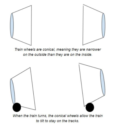
Have you ever considered how a train makes a turn? Really try and think about it, it has two wheels on a track separated by a distance but when it turns it doesn’t fly off the track. It’s not very intuitive but if a train was making a right turn, going along a curve to the right, the left wheel is traveling a greater distance since it’s on the outer curve. However, the two wheels traveling along the track are joined by a steel shaft that doesn’t break. So, what is the explanation for this phenomenon?

Figure 1: Differential Explanation

              Trains have conical wheels that allow for this freedom of motion at the track, they slide back and forth along the track allowing the train to tilt one way or the other. Now, the Pathfinder is not a train and will not be riding along tracks, but the same concept applies.


Encoders

The Pathfinder has 6 motors all connected to the same power source and in a perfect world if we supplied each of these motors with the same PWM command they would all go the same speed. However, this is not a perfect world and many factors can come into play when it comes to how fast the motor spins. First off, the whole premise behind the Pathfinder is that it can climb objects asymmetrically, that is each motor can be experiencing a different load which is one of the major reasons behind needing an electronic differential. Secondly, when we make turns we want to make sure the wheels are going at the speed we want them to account for the difference in distance traveled. And finally, due to natural mismatch in motor build we need to examine the difference in speed of the motors.

Herein lies the problem we have faced and have tried to come up with a solution for the past month or so. The motors on the Pathfinder currently do not have any encoders. We have looked at every possible type of encoder such as magnetic, optical, and any other possible type but we have finally realized that the only way of getting a truly good output from the encoder is by purchasing motors that already have encoders installed. The reason behind this is simply to achieve the greatest possible resolution with your encoders is to get your output prior to the gearbox. I can not stress that enough. If you ever have a project that you need encoders on make sure you either buy motors with an extended shaft or motors that have encoders included otherwise you might find yourself in the same situation. $200 later we now have our encoders.


Hall Effect Sensors

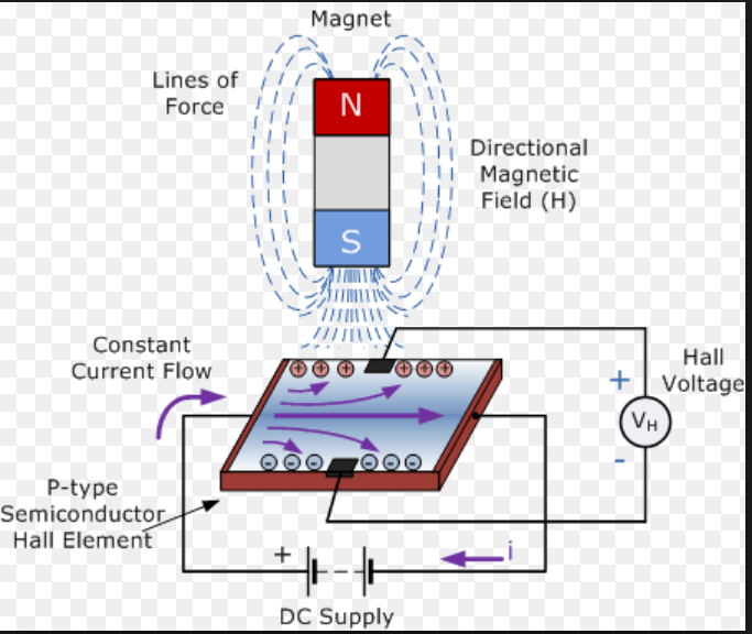
Now that we have motors with encoders connected prior to the gear-box we need to understand how they work.

Figure 2: Diagram of Hall Effect Sensor

              In the presence of a changing magnetic field, a charged semiconductor plate will deflect the flow of electrons from one side or the other. Consequently, one side of the plate will become more negative while the other becomes more positive. This is the basic principle of how a hall effect sensor works. A magnet is placed perpendicularly to the sensor plate and the Hall Voltage on the plate is observed. This is typically found in many encoding applications. There are two different types of Hall Effect sensors available, one that is a measure of flux density and the other is compared against some threshold voltage. We will be utilizing the latter since we are only concerned with the count and not the distance to the magnet. Another great feature of hall-effect sensors is their ability to toggle between states which means that bouncing is not an issue.

The encoders that we have paired with our motors have 6 pins associated with them, they are as follows:

  1. M1 (Motor Power Supply 1)
  2. GND (Encoder Ground)
  3. C1 (Encoder Channel 1)
  4. C2 (Encoder Channel 2)
  5. VCC (Encoder VCC)
  6. M2 (Motor Power Supply 1)


For each revolution of the motor we will receive 11 counts per channel which results in 22 CPR overall. Depending on the gear-box reduction ratio, which in our case is 280 (14 RPM), we can calculate the resolution as follows:

Figure 3: Determining the Resolution of Shaft Encoders

Note that this is the maximum resolution and there is an included error from the motor manufacturers data sheet. Depending on the amount of precision you need you can always use both channels, also if you need to determine direction of the motors then you will need to use both channels. For our purposes though we will only need to occupy one channel since pin allocation has become something of an issue for us.


Implementation

To accurately and efficiently read the encoders we will be using interrupts. By using interrupts we can allow the code to progress as normal and minimize the amount of time outside of the main loop. In order to make this 6 wheel differential work we have two options.

  1. We can set a desired speed that the robot travels and make all 6 wheels track that speed, or try to stay within a certain margin of that speed.
  2. We can set one of the motors to a certain PWM value that we are comfortable with and force the other 5 motors to follow that speed.

The issue with the second option is that even though we are sending a constant speed to one motor, it could fluctuate about some speed and that can cause issues with our control scheme. There is much less error when tracking a step input rather than a varying signal. Therefore the plan of action will be to set a desired speed, within capable limits of the motors, and make each motor follow that desired state.

In order to realize this we are going to need to design a controller that can follow this input. In my experience one of the easiest types of controllers to implement would be a proportional controller. Proportional control is relatively simple and comes at a low cost to the memory of our MC.

After running some experiments and playing with the gain we can figure out exactly how to implement this type of controller. For our purposes we will have 6 controllers, one for each of the motors. The input will be a constant velocity and the output from the encoders will be fed back to the summing junction to compare with the set point.


Software

Reading the Encoders

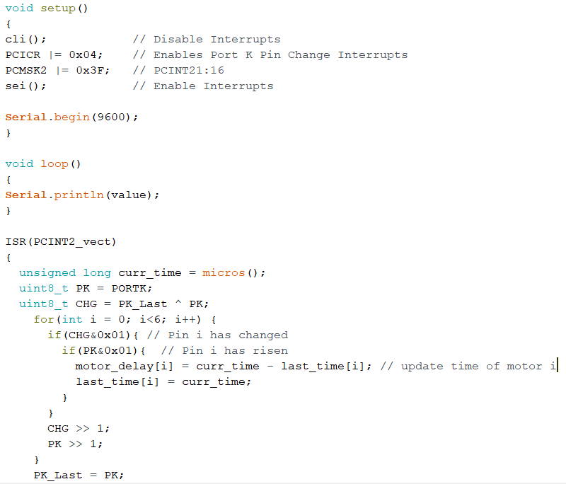
To efficiently read the encoders we will need to set up some interrupt service routines, specifically one for each motors encoder channel. This will be done similar to the following code:

Figure 4: Code for reading the encoders

              To get more information on how to set up interrupts like this please refer to the blog post regarding them HERE.

To verify that the output from the ISR was correct I applied a test voltage from a power source and found that the elapsed time between pulses was about 1450 microseconds for the 14RPM motors. After playing with the values and factoring in the gear ratio and CPR values the no-load speed of the 14 RPM motor was approximately 13.4 RPM which verified that these encoders are providing good feedback.


Control

              Knowing the limitations of your control is important when it comes to implementing a design. For example, we know that these motors can spin without any load at a maximum of about 14 RPM. So, we want to travel at a speed that will allow for the system to adjust for disturbances such as changing loads, error in sensor readings, and anything else that might present itself. Therefore, we will set the desired speed to a comfortable 10 RPM, this will allow the system to adjust in both directions.

We can include different equations in our ISR to calculate the speed but it would be easier if we just returned the delay between pulses and let the control track that instead. For a speed of 10 RPM it can be shown that the delay is about 1,950 micro seconds. If the actual speed of the motor is greater than 10 RPM then the delay would be less and if the motor was traveling slower the delay would be greater. Also, if we wanted to apply a gain to the controller we would need to come up with something that makes sense. If one of the motors was traveling faster than the set point by 1 RPM then that would translate to about 100 microseconds so if we wanted to allow the controller to respond aggressively to large errors a gain of about 4 would do the trick. With all of that in mind we can construct the controller as follows:

Figure 5: Code for Speed Controller


References

  1. https://www.arxterra.com/pin-change-interrupts/
  2. https://thewanderingengineer.com/2014/08/11/arduino-pin-change-interrupts/
  3. https://www.arduino.cc/en/Tutorial/BlinkWithoutDelay
  4. https://sciworthy.com/why-trains-dont-fall-off-the-track-when-turning/
  5. https://www.electronics-tutorials.ws/electromagnetism/hall-effect.html


Pin Change Interrupts

By: Jordan Smallwood (Project Manager and Electronics & Control)

Approved by: Miguel Garcia (Quality Assurance)


Table of Contents

Introduction

If you think back to your days of EE 346 you’ll remember the daunting feeling of dealing with interrupts. While we barely skimmed the surface, they’re really not that troublesome. The thing to note is that there are two types of interrupts, hardware & software. Hardware interrupts take place externally from the chip such as a physical button being pressed or any kind of input changing state. Software interrupts occur internally and most likely will be the result of a timer. Hardware interrupts can be further broken down into two more categories: external interrupts and pin change interrupts. Although pin change interrupts are technically external the difference with these is that they are not pin specific, the ISR corresponding to that pin will be called any time the condition is met from any pin on that port tied to the ISR. This can be more difficult to work with than the regular external interrupts which are pin specific but the advantage of using this type is that for most AVR boards any pin can be configured as a PCINT.

For our purposes we needed six interrupts, one for each of the motors encoders and although the ATMega 2560 has 6 external interrupts two of them were on the same pin as the I2C pins SCL and SDA which meant we needed to learn something new. Which leads us to a brief discussion of PCINT.


STEP 1: Turn on Pin Change Interrupts

To turn on PCINT’s you need to configure the PCICR (Pin Change Interrupt Control Register) according to your specific purposes. This can be done the following way:

Figure 1: Pin Change Control Register and description

Since we will be routing all of our encoders to PCINT23:16 it makes sense that we should enable PCIE2. To do so we will include the line of code: [PCICR |= 0x04]. This can be done many ways but the idea is that we set that pin to 1 while keeping the other bits unchanged.


STEP 2: Pin Selection

Although any pin mapped to PCI2 will run that ISR, that is only if we set their masked bits in the Pin Change Mask Register. We only need to use 6 of the 8 pins mapped to PCI2 so we can still use the other analog-in pins if we need to later.

Figure 2: Pin Change Mask Register 2 Description

Again, we only will be wiring encoders to PCINT 16:21 so we will need to include the following line of code: [PCMSK2 |= 0x3F;].


STEP 3: Write the ISR

Now that you have configured your interrupt control registers and decided which pins are going to actively set the ISR all that is left is to tell the computer what to do when it reaches this state. Any time you ever write an ISR you should keep it as short as possible and when declaring variables make sure to make them of type volatile so it is never optimized. To define the ISR just include the following:

ISR(PCINT2_vect){} // Port K, PCINT16-PCINT23.

Finally, you will have something like this:

Figure 3: Pin Change Interrupt Example


References:

  1. https://thewanderingengineer.com/2014/08/11/arduino-pin-change-interrupts/

Buck Converter Efficiency

By: Mohammad Yakoub (Mission, Systems, and Test)

Verified By: Jordan Smallwood (Project Manager)

Approved by: Miguel Garcia (Quality Assurance)


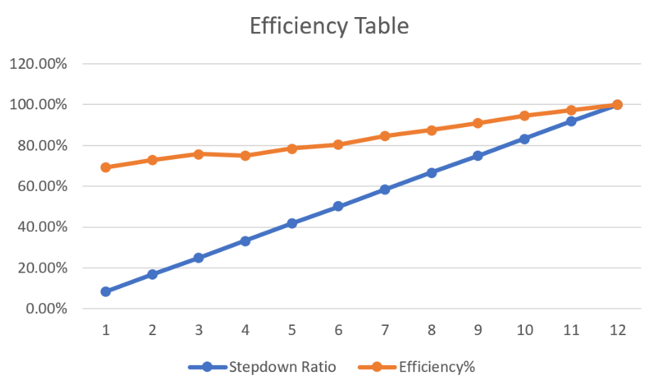
A Buck converter is a DC-to-DC power converter which steps down voltage (while stepping up current) from its input to its output. Switching converters such as buck converters provide much greater power efficiency as DC-to-DC converters than linear regulators, which are simpler circuits that lower voltages by dissipating power as heat, but do not step up output current. That is why we considered to use it to step down the output of our main battery to a voltage that can work for our Arduino board. The efficiency of the buck converter is extremely high reach 90% efficiency  and higher in some cases. However from my experience with the buck converter the efficiency of the buck converter seems to decrease as the difference between the input and output increases. Fortunately, for the purposes of our build we are stepping from 12v volts to 9v, which puts us at 91% efficiency. The efficiency testing the power of the input vs the power of the output under different step down ratios. The input voltage is 12v, different output voltages that were tested. Starting from 1v to 12v, and each step I measured the power of the input and the power of the output and from there I was able to calculate the efficiency of the buck converter at different step down ratios.


Figure 1: Plot of Buck Converter Efficiency at Various Step-Down Ratios


References:

  1. http://www.learnabout-electronics.org/PSU/psu31.php
  2. https://en.wikipedia.org/wiki/Linear_regulator


Custom Commands – Bluetooth Communication

By: Jordan Smallwood (Project Manager)

Approved by: Miguel Garcia (Quality Assurance)


Table of Contents

Introduction

One of the many benefits of working with the Arxterra App is the ability to create custom commands and communicate with your robot over Bluetooth. Although many of the necessary commands have been predefined there is still plenty of room to create custom user defined commands to make navigating and controlling your robot a breeze.

In this blog post we will examine the MOVE command which will allow the user to control the robots speed and orientation using the D-Pad on the Arxterra App. We will walk through how to set this up step-by-step to ensure that future semesters can focus on other aspects of their project.


Parts Required

  • Wheels with electric motors (Pathfinder has 6)
  • Motor Driver (Pololu VHN 5019)
  • Microcontroller (Arduino Mega2560)
  • Bluetooth Device (HM-10)
  • Android or iOS Device with Arxrobot App (iPhone 6)
  • Power for Electronics (12V Lead Acid Storage Battery)
  • Robot3DoT Library

Step 1: Physical Connections

First and foremost, you will need to wire everything up, that is motors to motor driver(s) and motor driver to the microcontroller. This can be done by looking up the data sheet for your specific motor driver and wiring accordingly. Also, you will need to connect your Bluetooth device to the microcontrollers serial port as well ensuring that TXD -> RXn & RXD -> TXn.


Step 2: Downloading the Arxterra App

In order to gain access to the Arxterra App you will need to get in contact with Jeff Gomes. The app is available for both android and iOS devices, however, it is easier to get the app onto an android device. There is one additional step when it comes to installing the app on an iPhone. Since the App store is a little bit more selective as to what they offer, the Arxrobot app is still considered to be in beta testing and you will need your specific Apple user ID to get access.


Step 3: Import the Robot3DoT Library

This is where you will find a lot of the code that will make your life a million times easier. This library can be found here. In order to import this library you will first need to download the library, leaving it in its .zip format. Once you have downloaded it you can import it into the Arduino IDE by opening your computers file folder and dropping that file into the library file within your Arduino folder.


Step 4: Including and using the Robot3DoT Library

After you have imported the library you will need to open a new script within the Arduino IDE. Now you will want to include this library in the sketch you have created and you should see at the top of your code the library include statements. If you would like to get a better understanding of how the code works you can view the libraries by finding them in the Arduino folder under libraries and selecting the libraries .cpp file. This can be very beneficial as you can make sure this code works for your specific purpose and if not then you can make modifications as needed.

Now you will need to insert the following lines of code to be able to use the command handler properly. All of these are entered before your setup code.

  1. Robot3DoTBoard Robot3DoT; // Instantiate as Robot3DoT at end of class header
  2. const uint8_t CMD_LIST_SIZE = 1; // total number of custom commands
  3. void moveHandler(uint8_t cmd, uint8_t param[], uint8_t n);
  4. Robot3DoTBoard::cmdFunc_t onCommand[CMD_LIST_SIZE] = {{MOVE,moveHandler}};


  • Note that for custom commands you will need to define the specific ID for that command. For example, the MOVE command is already associated with ID 0x01 and does not need to be redefined.

Within the setup code you will want to insert the following:

  1. Serialn.begin(9600); // This opens up the serial port that your Bluetooth device is connected to.
  2. Robot3DoT.begin(); // This is a predefined setup function within the Robot3DoT Library
  3. Robot3DoT.setOnCommand(onCommand, CMD_LIST_SIZE);


In the main loop make the call:

  1. Robot3DoT.loop();

Now you’re ready to write your command handler functions. The MOVE function already has functions that are associated with it but you are able to write your own functions if you’d like. For our purposes we wanted a simple move function to control it’s direction at a specified speed. The directional pad has four buttons: up, down, left and right. They all have their own unique ID associated with them and by processing the data sent to the Arduino we can assign their values accordingly. For example:

Figure 1: Implementation of a command handling function, Credit: Mark Huffman


Step 5: Verify Bluetooth Connection

This is perhaps the most troublesome step. When I was setting all this up I could not seem to get any sort of communication with the app and the Arduino. After wasting hours of changing serial ports, examining the libraries and looking up troubleshooting methods I discovered three key issues.

  1. The HC-06 device we had from a previous semester was defective. I discovered this while looking up troubleshooting methods. A simple way to determine if your device is defective is by creating a “transmission loop”. This is done by shorting the RXD and TXD pins on the device and making sure it is turned on (If it doesn’t even turn on that’s your first clue). Download the free app Bluetooth terminal on your iPhone or Android and connect to it. Once you are connected you can send the device ASCII characters and it should send back exactly what you sent. If you are getting no response then your device is most likely defective.


  1. There are different kinds of Bluetooth technology. iPhones only operate with BLE communication whereas Androids can use a variety. If you plan on using an iPhone to control your robot make sure you have an HM-10 or HM-11 device to connect to. Also, make sure that within the Arxrobot app phone configuration settings you have selected the proper Bluetooth connection.


  1. For some reason the Arduino Mega will not allow you to upload code if you have Bluetooth connected to the Serial port. In which case I moved the Bluetooth to the Serial1 port. Since I changed the serial port physically and not within the software there was no established communication line. Let this be a reminder to make sure the serial port you are using is being called within the code otherwise this can be a nightmare.


  • Hopefully future semesters can learn from my shortcomings and not have to struggle with this aspect of their project.

Step 6: Drive Around or Something

Now that you have setup Bluetooth communication, defined your motor functions and wrote the code to establish communication between the app and your device you can literally do anything you want from blinking an LED to autonomous GPS navigation. Just know that all of your commands are going to be in this type of format and you can extract whatever information you want and do with it what you will.


References

  1. https://www.arxterra.com/goliath-fall-2017-app-setup-and-remote-control-user-guide/
  2. https://www.arxterra.com/goliath-fall-2017-custom-telemetry-custom-commands/

Rocker-Bogie Suspension System

By: Adolfo Jimenez (Manufacturing)

Verified By: Jordan Smallwood (Project Manager)

Approved by: Miguel Garcia (Quality Assurance)


Table of Contents

Introduction:

In order to mimic the suspension capabilities of the rovers sent to Mars by NASA, our rover will incorporate the same rocker bogie suspension system utilized by the Mars rovers to traverse an extreme desert-like terrain. This suspension system, introduced with the original Mars Pathfinder project, is the same design preferred by NASA for nearly all the Mars rovers. The main advantage of this type of suspension system is that the load on each wheel is nearly identical and thus allows an equal distribution of force regardless of wheel position. Taking into consideration the harsh terrain found on Mars this type of suspension system provides a better alternative to that of the common 4-wheel drive soft suspensions found on most automobiles.

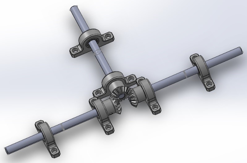
Figure 1: View of Differential Gearbox System without Box


Design enhancements:

For our project, since we are mainly building upon the design of previous semesters, we can utilize the things they did correctly and build upon things they may have overlooked. The main design difference, as it pertains to the suspension system, is the addition of a differential gear box. Whereas previous semesters utilized a barely functioning differential bar, or no differential at all, this semester we decided to remove the bar entirely and replace it with a much more functional differential gear box. This addition of a differential gear box will offset the wheel assemblies by about .8 Inches on each side and raise the main platform about .38 inches higher from the ground. Upon further research of rover suspension systems our group discovered a helpful blog on a website called Beatty Robotics. The website provides many helpful blogs describing the design and creation process for many custom Mars rovers and other robots. The particular blog post that helped us meet our needs pertained to a differential system used for a custom Spirit II Mars rover. Feedback on the blog pertaining to the parts used lead us to the website McMaster-Carr where we were able to order the parts to assemble our own Differential.


Suspension- Wheel Assembly:

Figure 2: Wheel Assembly

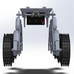
The wheel assemblies contain a total of 6 wheels with a symmetric build for both sides. Each side contains 3 wheels which are connected to each other by two links. The main linkage called the rocker has two joints, one affixed to an axel forming the differential mechanism and the other connected to the remaining two wheels. This linkage from the rocker to the other linkage between the two wheels is known as a bogie (hence the name rocker bogie). To go over an obstacle, the front wheel is forced against the obstacle by the center and rear wheels. The rotation of the front wheel then lifts the front of the vehicle up and over the obstacle. The middle wheel is then pressed and pulled against the obstacle by the rear and front wheels respectively until the wheel is lifted up and over the obstacle. Finally, the rear wheel is pulled over the obstacle by the front two wheels.


Suspension- Differential Gear Box:

Figure 3: Differential Gear Mechanism Close-up

The differential is composed of three identical beveled gears situated 90-degrees from each other at the center of the rover. Each gear is affixed to a 6-inch steel drive shaft that is mounted to the rover body by 2 mounted sleeve bearings. One gear connected to the left, one gear connected to the right, and the last gear assembled onto the main platform. The two rods facing opposite of each other on the left and right of the robot help serve as axels for the wheel assemblies. The axils are connected to the wheel assemblies by 2 parallel aluminum tubes that make up the rocker bogie suspension system. The inclusion of this differential insures that the robot’s body and pitch angle are always adapted even if one side of the rover steps over an obstacle. If one leg goes over an obstacle, an opposite force is applied to the other leg. So, if one leg goes up, the other leg goes down. This downward force onto the opposite leg helps the robot maintain traction in the leg assembly that is still on the ground. The way this works is when one side changes in pitch, say for instance one side begins climbing over an obstacle, this mechanism rotates the main body around the rocker joints by the average rotation angle of the two sides. For this differential mechanism, all gear ratios are the same. That means if the left gear rotates 10 degrees and the right gear rotates 20 degrees, the main platform will rotate 10 + 20 = 30/2 = 15 degrees or the averaged amount. This keeps the main box more level (less tilted) than it normally would be when going over large, uneven obstacles.


References:

  1. https://www.arxterra.com/2016-pathfinder-design-and-manufacturing-rocker-bogie-suspension-system-design/
  2. https://www.arxterra.com/news-and-events/members/pathfinder/pathfinder/pathfinder-generations/pathfinder-generation-4/
  3. https://en.wikipedia.org/wiki/Rocker-bogie
  4. http://citeseerx.ist.psu.edu/viewdoc/download?doi=10.1.1.538.6955&rep=rep1&type=pdf
  5. http://beatty-robotics.com/differential-for-mars-rover/
  6. https://www.mcmaster.com/

Pathfinder Preliminary Design Blog Post – Spring 2018

By: Jordan Smallwood (PM), Diane Kim (E&C), Mohammad Yakoub (MST), Adolfo Jimenez (Manufacturing)

Approved by: Miguel Garcia (Quality Assurance)


Table of Contents

Project Overview

By Jordan Smallwood

Project Objective:

The Pathfinder is a project that has been passed down from generation to generation. The originators built the chassis and original idea back in the fall semester of 2016. A rover like this does not make its way into the EE department that often since the lot of us don’t typically have much experience with welding and fabrication. Luckily enough for our group we will be picking up the slack where the previous teams had left off. It seems as though every semester that attempts this project faces failure in one way or the other whether it is the differential rocker-bogie mechanism or leaving wires exposed to short the 12V golf cart battery. Either way, the overall aim of this project is to finally finish what other groups have started and that will be defined in the following sections of this report.


Mission Objective:

By Jordan Smallwood

The Spring of 2018 Pathfinder will follow the path laid down by previous Pathfinders. The mission will begin in front of the CSULB library where the rover will exit its cocoon state. The rover will then proceed to begin its journey through campus, a 0.09 mile journey to its charging station. There will be 10 predefined GPS checkpoints along the way and the rover will traverse a flight of stairs. Once the rover has arrived at the charging station it will begin to track the sun and provide the Arxterra user with up to date battery level conditions. Specifically the Pathfinder will demonstrate the following:

  • Custom solar panels capable of tracking the sun and exhibiting optimum orientation so that battery charge takes the least amount of time.
  • The rover will be able to enter and exit a cocoon state. The term cocoon state implies that the solar panes will fold up so that in the event of a dust storm the solar panels will not become damaged. This state will be entered if the rover is in launch, a dust storm or whenever the rover is operating over steep terrain.
  • The rover will be able to communicate with the Arxterra app providing information like battery level, panel angles, panel voltages and charging current.
  • The solar panels will have a form factor identical to those of the Spirit and Opportunity Mars Rovers.
  • The rover will exhibit a 6-wheel slip differential for turning and traversing rough terrain. Since the robot will be climbing over random objects, some wheels will not require the same speed as other wheels and this needs to be considered while operating the rover.
  • Demonstration of GPS navigation with obstacle avoidance.
  • The course mapped out by F’16 and S’17 will be the same course for S’18.
  • There shall be no modification to the rover that stands in the way of high desert operation.

Project Requirements

By Jordan Smallwood

Level 1 Requirements

  1. The pathfinder will travel a 0.09 mile course. This course includes going up a set of 3 stairs at a 70 degree incline and another set of 3 stairs with a decline of 70 degrees.
  2. Pathfinder shall launch from a cocoon state
  3. The Pathfinder will enter and exit the cocoon state by Arxterra app user input.
  4. Pathfinder shall allow the user to enter the “articulate state” program module which will be available once the Pathfinder has exited its cocoon state. This sequence will direct the solar cells at the proper orientation to allow max charge of the battery.
  5. The Pathfinder will update the user with information about panel angles, GPS location, battery level and charge current when in the “Articulate state”.
  6. The overall solar panel system will consist of two side panels, a rear panel and a base panel.
  7. The solar panel design will be identical to those of the Spirit and Opportunity Mars Rovers.
  8. A 6-wheel electronic slip differential shall be implemented
  9. Wheels under a no-load condition will be considered and power to that motor will be decreased.
  10. The Pathfinder shall demonstrate obstacle avoidance while making its journey through campus.
  11. Any modifications made to the Pathfinder shall not inhibit the rover’s ability to operate in high desert condition.
  12. Rocker bogie mechanism shall be improved by implementing a differential gear-box system as opposed to the differential bar.


Level 2 Requirements

By Jordan Smallwood

  1. Course Duration
    • The power budget of our overall design will determine the duration of our course, once this has been completed the actual distance traveled will either be verified by this or will have to be changed to a shorter distance.
    • In order to travel up these stairs our mass report along with our motor mock up will verify that this can be accomplished.
  2. Cocoon Launch
    • To perform the cocoon state function the solar panels will be mounted to worm gears attached to DC stepper motors to ensure smooth operation.
  3. Enter/Exit Cocoon State
    • The Pathfinder shall communicate via Bluetooth with the Arxterra user and will have an interface allowing the user to enter/exit the cocoon state.
  4. Articulate State
    • The articulate state module will adjust the positions of the solar cells using a proportional controller.
    • The proportional controller will accept the charge rate as an input and will output changes in orientation.
  5. Telemetry
    • While communicating with the user via Bluetooth on the Arxterra app the Pathfinder shall respond with packets of information related to this information.
  6. Solar Panels
    • These four panels will be constructed of aluminum such that the rover can operate in the harsh desert conditions typical of Mars.
    • The side and rear panel’s will be capable of position orientation to enter and exit the cocoon state and also optimize battery charge
  7. Solar Panel Form Factor
  8. 6-Wheel Electronic Slip Differential
    • A coded differential will be used ensuring that the wheels are spinning at the same rate.
    • IR range sensors will be mounted to the motors to determine the velocity of the wheels
    • Current sensors will be used to determine the load on the wheels
  9. No Load
    • To conserve energy, the rover will stop rotation of a freely moving wheel using the current sensors
  10. Obstacle Avoidance
    • Ultrasonic sensors will be used to determine if an obstacle is in its path.
    • An obstacle avoidance routine shall be implemented.
    • The rover will not make any attempt to climb an object that it is unable to clear
  11. Modifications
  12. Rocker-Bogie Mechanism
    • The differential gear box will be constructed of three miter gears, three machined shafts, six mounted bearings and shaft collars
    • This mechanism will be mounted below the Pathfinder and enclosed in an aluminum box with the electronics.
    • This box shall be easily removed for inspection and maintenance.


Work Breakdown Structure

By Jordan Smallwood

Figure 1: Work Breakdown Structure for Pathfinder Project


Product Breakdown Structure

By Mohammad Yakoub

Verified By: Jordan Smallwood

Figure 2: Product Breakdown Structure for Pathfinder Project


Resource Reports

By Mohammad Yakoub

Verified By: Jordan Smallwood

Power Report:

Figure 3: Preliminary Power Budget

Mass Report:


Figure 4: Preliminary Mass Report

Cost Report:

Figure 5: Preliminary Financial Report


System Block Diagram

By Mohammad Yakoub


Figure 6: Preliminary System Block Diagram


Interface Matrix

By Jordan Smallwood

Figure 7: Preliminary Interface Matrix


Software Design

By Jordan Smallwood

  1. Obstacle Avoidance: In order to make sure that the Pathfinder does not fail the mission, ultrasonic sensors will be used in the front of the rover to verify that an object is not too large for Pathfinder to climb over. This routine will take place within the software and more information will be provided at a later time.
  2. GPS Checkpoint Navigation: Pathfinder will use GPS location information from the on-board iPhone or Android device and follow the course as defined in the mission objective. This will involve some type of digital controller and will be implemented in software. Again, these are preliminary concepts and not much has been constructed as of now but will be provided as the semester continues.
  3. Motor Functions: Pathfinder will perform very basic motor functions such as go straight, turn around, turn left, turn right and stop.
  4. Read Encoders: To determine the speed that each wheel is spinning this function will examine the current speed of each wheel by counting the pulse trains given from the IR sensors mounted to the wheels.
  5. Stop Motors Under No-Load: By examining the current associated with each motor we can make sure we are not spending energy for nothing. This will most likely be a conditional statement and if the current state of the motor is under a no-load condition, then the power supplied will be cut off. Reinitializing the motor speed once a load is present will have to be tested though.
  6. 6-Wheel Differential: When making a turn the speeds of each motor needs to be considered since they may be traveling along different paths but need to arrive at the destination at the same time. By examining the speeds of the motors we can modify the PWM signal applied to ensure that we are traveling smoothly.
  7. Exit Cocoon/Articulate Solar Panels: When the user decides to either exit or enter the cocoon/articulate state the microcontroller will apply the functions necessary to do so.


Fritzing Diagram

By Diane Kim

Verified By: Jordan Smallwood

Figure 8: Fritzing Diagram

The components inside the chassis contains the following: batteries (2), dual motor drivers (3), ultrasonic sensors (2), servos (2), IR sensors (6), motors (6), and the Arduino Mega 2560 (1). Unlike the previous version which only had 1 battery, we will be using 2 batteries to power up the motor to decrease the size. The ultrasonic sensors are used to navigate the rover. The IR sensors are to be placed beside the wheels to measure the RPM by toggling the signal whenever the spoke of the wheel passes by. The VNH2SP30 dual motor drivers is used to control the speed of the motors thus the wheels. The servos are used for the pan tilt. All the peripheral systems are connected to the Arduino Mega 2560 to input and output signals.


Mechanical Design

By Adolfo Jimenez

Verified By: Jordan Smallwood

2D Drawings (Dimensions all in inches):

Rear and Top Side View:

Side View (left):

Figures(9,10,11): 2D Layouts of Physical Structure

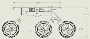
For the pathfinder project, since we are mainly building upon the design of previous semesters most of the dimensions and physical parts will remain the same. The main design difference for the time being is the addition of a differential gear box. Whereas previous semesters utilized a barely functioning differential bar, this semester, we decided to remove the bar entirely and replace it with a much more functional differential gear box. This addition of a differential gear box will offset the wheel assemblies by about .8 Inches on each side and raise the main platform about .38 inches higher off the ground.

Differential Gear Box

Figures(12,13,14): 3D Layouts of Physical Structure

Two planar aluminum tubes for the rocker boogie suspension system are connected to each other by a differential mechanism. When one side changes in pitch say for instance one side begins climbing over an obstacle, this mechanism rotates the main body around the rocker joints by an average angle of two sides. Gear A connected to the left, gear B connected to the right and gear C is assembled on the main platform. In differential mechanisms, all gear ratios are the same. That means if gear A rotates 10 degrees and gear B rotates 20 degrees, the main platform will rotate 15 degrees.


Verification and Validation Plans

By Mohammad Yakoub

Verified By: Jordan Smallwood


Figure 15: Verification and Validation Part 1


Figure 16: Verification and Validation 2


Test

By Mohammad Yakoub

Verified By: Jordan Smallwood

3.3.1 Final Run

Description: The Pathfinder will follow a course That is 0.9 miles in length. The course will includes going up a set of 3 stairs at a 70 degree incline and another set of 3 stairs with a decline of 70 degrees. The robot will start the course in a cocoon state and will deploy solar panels.

Test Environment: Outside the classroom


3.3.2 Proportional Controller

Description: The Pathfinder will adjust solar cells using proportional controller.

Test Environment:  Inside a classroom


3.3.3 Cocoon

Description: User will use the Arxterra App to enter and exit cocoon mode.

Test Environment: Inside a classroom


3.3.4 Articulate Mode

Description: The user will use the arexterra App to activate ‘articulate mode’, and receive feedback from the Arxterra App.

Test Environment: Outside the classroom


3.3.5 Weighting

Description: Placing the fully assembled Pathfinder on a weighing scale.

Test Environment: Inside a classroom


3.3.6 Scale  

Description: Goliath should resemble the ‘Spirit Mars Rovers’

Test Environment: Inside a classroom


3.3.7 Obstacle Avoidance

Description: The Pathfinder will avoid obstacles while running the final course.

Test Environment: Outside the classroom


3.3.8 Solar panels

Description: The Pathfinder solar Panels will be made out of metal and use a stepper motor

Test Environment: Inside a classroom


3.3.9 Feedback

Description: The Pathfinder will relay information charging panel angles, GPS location, battery level and charge current through the Arexterra App

Test Environment: Outside the classroom


3.3.10 Diff Gearbox

Description: The Pathfinder box will be made out of three miter gears, three machined shafts, six mounted bearings and shaft collars.

Test Environment: Inside a classroom


3.3.11 Diff Gearbox Case

Description: The Pathfinder Diff Gearbox will be enclosed in an aluminum box.

Test Environment: Inside a classroom


3.3.12 Mods

Description: The add modifications on the Pathfinder will hinder its ability to function on hard terrain.

Test Environment: Inside a classroom


3.3.13 RPM

Description: Use current source to measure the RPM of each wheel at different loads.

Test Environment: Inside a classroom


 Schedule/Planning

By Jordan Smallwood


Figure 17: Schedule Part 1


Figure 18: Schedule Part 2


Figure 19: Burndown Chart


References

  1. https://www.arxterra.com/pathfinder-s17-preliminary-project-plan/
  2. https://www.arxterra.com/spring-2016-pathfinder-preliminary-design-documentation/
  3. https://www.arxterra.com/the-pathfinder-fall-2016/
  4. https://www.arxterra.com/spring-2016-pathfinder-system-block-diagram-interface-matrix/

Making A Turn

By: Jordan Smallwood (Project Manager)

Approved by: Miguel Garcia (Quality Assurance)

The pathfinder will be performing tank type turns, that is it will be pivoting about it’s center to adjust it’s orientation. This can be done by simply adjusting the direction of each of the wheel sets. For example, if you wanted to make a left turn you would do so by setting the right wheels forward and the left wheels backward.

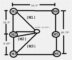
Depending on where you would like to end up at the end of a turn you must consider the arc lengths that each wheel must travel to perform a certain turn. The pathfinder will be pivoting about it’s center point which is described by the following:

Figure 1: Derivation of soft differential speed ratios

By examining the above figure, we can see that motors 1, 3, 4 and 6 will be traveling along the same arc length. The only difference is that the set of motors 1 & 3 will be spinning the opposite direction of motors 4 & 6. Motors 2 & 5 will also be traveling along the same arc the only difference is the radius related to that arc is smaller than the other motor sets.

If we calculate the radii of each of the motors we can determine an appropriate motor speed ratio to pivot the pathfinder.

Figure 2: Calculation of Magnitudes

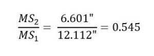
If we let MS1 be the speed of motors 1, 3, 4 & 6 and let MS2 be the speed of motors 2 & 5 then we can say the following:

Figure 3: Relating Motor Speeds

Now we know that in order to pivot about the center point we need to have MS2 = 0.545*MS1. In a perfect world all of our motors would be matched and the PWM signal to each would be identical and we could simply supply a PWM signal to each motor with that ratio in mind. However, this is not a perfect world and the load on each motor is constantly changing so instead we will need to monitor the speed of each wheel with simple encoders. Since our motors do not include encoders we will have to engineer our own. For our purposes this will be simple IR sensors strapped to the motors aimed at the spokes on our wheels. We could potentially purchase new motors that have included encoders prior to the gearbox so that we can achieve much better resolution but that will have to be a project for a later semester.


References

  1. https://www.arxterra.com/digital-slip-differential-voltage-ratio/

Pathfinder S’17 Final Blog Post

By Martin Diaz (Project Manager)

Edgardo Villalobos (Solar – Design and Manufacturing Engineer)

Anthony Dunigan (Chassis – Design and Manufacturing Engineer)

Renpeng Zhang (Electronics and Control Engineer)

Abdullah Albelbisi (Missions, Systems, and Test Engineer)

Table of Contents

Executive Summary

By Martin Diaz (Project Manager)

Program Objective

1. Articulating custom solar panels which are able to track the sun and enter/exit a cocoon state. The panels will be modular allowing the remote identification (telemetry) and astronaut replacement of a broken module. Additional telemetry requirements include providing information on articulation angles, panel voltages, charging current, and battery fuel level. A cocoon state shall be used during simulated launch, dust storms, and operation over steep terrain.

2. Form factor of the solar panels will be identical to the panels on the Spirit and Opportunity Mars rovers. Sizing of the panels will be consistent with the existing chassis and meeting the form factor of the Mars rovers. Specifically, the size of the panels relative to the size of the chassis will be identical to the mars rovers (scaled model).

3. Electronic slip differential 6-wheel Drive for turning and traversal of rough terrain, specifically, the outside and inside wheels will turn at different speeds while turning, plus wheels under no load conditions will stops spinning.

4. Demonstration of GPS navigation mode with obstacle avoidance (articulating LIDAR sensor)

5. The Mission Objective is to traverse the same course defined for the Fall ’16 Pathfinder.

6. Based on the fixed size of the articulating solar panels, efficiency, sun’s path during time of mission, and the mission objective, the project will propose charge time and batteries for the rover. Margins must be identified.

7. No modification to the pathfinder rover shall preclude future High Desert operations (High temperature materials with cooling system as needed). a. Wheels b. Pan/Tilt platform c. AC Unit

Mission Profile

The S’17 Pathfinder will commence it’s Mission by first exiting a “cocoon state” in front of CSULB’s library, then  traversing .09 miles to it’s destination charging station. To reach it, the Pathfinder will need to traverse up and down a set of 3 steps. GPS Navigation mode will use 11 predefined checkpoints including start and finish L-L coordinates. Along the way, the Pathfinder will operate in articulation mode, in which the solar panels will track the sun and provide current telemetry of each of it’s 36 cells to a sync’d Arxterra App user within Bluetooth range.

Key Features

Custom Arxterra Control Panel

  • Buttons for opening and closing panels
  • Buttons for entering and exiting panel articulation mode
  • Meters that show each solar cells output voltage

Proper Rocker Bogie Suspension System

  • Obstacle Climbing
  • Keeps all wheels in contact with ground in uneven terrain

Cocooning and Articulating Solar Panels

  • Solar panels can fold up and down by use of stepper motors and worm gear.
  • Solar panels will move up and down to find a better position for increase sunlight.

Solar Cell Telemetry

  • Solar Cell Current Telemetry that can be viewed through Arxterra control panel.

Pan and Tilt system for lidar sensors


Electronic Slip Differential

  • Inside and Outside wheels will spin at different speeds
  • Any tires under no load will stop spinning

Autonomous GPS navigation and Obstacle Avoidance

  • In autonomous mode the pathfinder will travel to the next coordinate and avoid obstacles along the way.

Rotary encoders to measure each wheel rpm

  • Wheel rpm will be monitored and used in electronic slip differential program.

Level 1 Requirements

  1. L1.1 Pathfinder shall travel a .09 miles course. Course includes going up a set of 3 stairs at 70 degree inclination and down a set of 3 stairs with a downward slope of 70 degree.
  2. L1.2 Pathfinder shall launch from cocoon state. Solar panels folded upward at 85 degrees from base.
  3. L1.3 Pahtfinder shall allow user to manually execute “enter cocoon state” program module via arxterra App to enter into cocoon state at any time.
  4. L1.4 Pathfinder shall all user to manually execute “exit cocoon state” program module via Arxterra app to exit cocoon state at any time. 85 to 210 angle.
  5. L1.5 Pathfinder shall allow user to execute “articulate state” program module which is available after the pathfinder has completed the “exit cocoon state” sequence in order to articulate the solar cells directly at the sun limited to the full bend of each wing, which is between 210 and 85 degrees relative to the solar panel base. articulate state is based on an “articulate state” program module which precisely actuates each wing’s stepper motor module’s parameters which include time of day, GPS location, orientation, and local sun trajectory.
  6. L1.6 Pathfinder shall provide updates of solar panel articulation angles which come from the ‘articulate state” program module.
  7. L1.7 Pathfinder will provide solar panel voltages and charging current by capturing each modular panels electrical output separately.
  8. L1.8 Two side panels, a butt panel, and a base panel shall be modularly encapsulated and wired.
  9. L1.9 From factor of the solar panels will be identical to the panels on the spirit and opportunity.
  10. L1.10 Electronic slip differential 6 wheel drive shall be implemented by an “ESD” program module.
  11. L1.11 Wheels that are not in contact with terrain shall be actuated by “ESD” program module to stop spinning by using currents that match free spinning wheel characteristics as inputs.
  12. L1.12 Pathfinder shall demonstarte obstacle avoidacne during course traversal by articulating 2 lidar sensors via pan and tilt system. The lidar sensors will provide input and be controlled by the waypoint navigation program module used during the fall 16 semester
  13. L1.13 Pathfinder will utilize “waypoint navigation” program module for autonomous GPS navigation
  14. L1.14 Rocker bogie system shall be improved by closely modeling the suspension mechanics behind the mars exploration rovers, curiosity and spirit.
  15. L1.15 Pathfinder will not hinder future use of pathfinder in high desert condition by modification of wheels, pan/tilt platform, and AC unit.
  16. Pathfinder will be ready to demonstrate mission profile and project objectives by may 12th, 2017

System Design

By Abdullah Albelbisi (Missions, Systems, and Test Engineer)

System Block Diagram
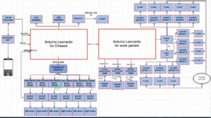
Mission Command and Control

We have used Axterra app to develop a custom command to control ( “Cocoon state”, articulate state”, telemetry)


“Cocoon State” : is a state where we can control the panels to either close or open. The initial benefit from cocooning is to prevent the solars from harm causing by natural effect. We control it

by pressing either “cocoon on” or “cocoon off” on the Axterra app.


“Articulate State” : is a state to allow the solar panels to follow the most dense direction of light to produce power and charge the battery. It can be controlled by pressing either “on” or “off” on the Axterra app.
“Telemetry” : 12 custom telemetries have been assigned to address a visual amount of energy is being produced by every 3 solar cells.

Experimental Results

HC-Sro4 Ultrasonic Sensor Test

Wheel Forces Calculations

Solar Current Sensor Experiment

Stepper Motor Control

Solar Panel Voltage Calculations

Encapsulation Trade Off Study

Solar Manufacturing

By Edgardo Villalobos (Solar – Design and Manufacturing Engineer)

As a requirement, the Pathfinder was to have a solar panel in the shape of the solar panels on the Spirit and Opportunity Rovers that would charge the 12V 7Ah battery onboard the Pathfinder. The wings on the solar panel needed to be able to open and close to a cocoon state and also articulate to the sun. Another requirement on the solar panel was to obtain the voltage differential from each of the solar cells to make it easier to pinpoint the location of the non-functioning cell.
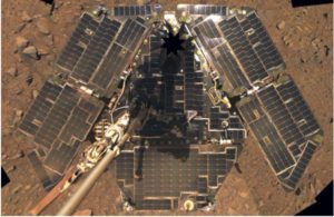
The previous semester’s solar panel group had made the wings out of aluminum, which I found to be a little too heavy for the worm gear mechanism used to make the wings open and close. I replaced the aluminum wings with plexiglass in order to lighten the load, which I now know was a mistake as the plexiglass was not strong enough and will not withstand the heavy heat.


The solar panel consisted of 36 6V 100mA encapsulated solar cells that were arranged in series and parallel in order to achieve the right amount of voltage and current to charge the battery in a timely manner. The rule of thumb with solar panels is that the voltage required to charge the battery needs to be one and a half times bigger than the voltage of the battery in order to stay consistent. The cells were arranged to achieve 18 volts. Each panel consisted of two rows in parallel and three cells in series in each row, theoretically making a total of 18V 200mA. The whole solar panel theoretically achieved 18V 1.2A. The solar cell array was then attached to the first two terminals of the solar charger that was placed on the Pathfinder.
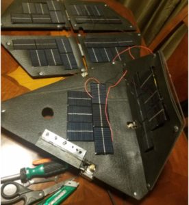
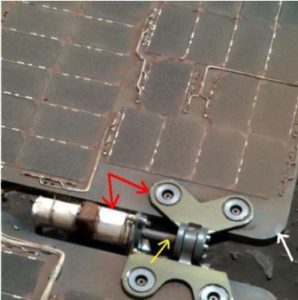
In order to fix the worm gear issue, a box with ball bearings could be made to hold the worm gear and spur gear together for a tighter grip. Another solution is to make the size of the gears larger. The problem here is that the weight of the wings was causing the hinge to bend away from the worm gear. In order to get the ball bearing box to work, the placement of the wings and hinges would also need to change. The gears could also use a little oil/grease for easy movement.


Another problem with the wings is that they don’t fully close onto themselves as the material on top of the wings gets in the way. A solution to this could be the use of L-hinges. Although the L-hinges aren’t the nicest to look at, they do provide room for overlap.
In conclusion, I was unable to get the solar panels articulating/cocooning mechanism to function correctly. With the little changes I described will make it work.

Chassis Manufacturing

By Anthony Dunigan (Chassis – Design and Manufacturing Engineer)

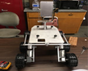
The new chassis design was based on the fulfilling the requirement of improving the rocker bogie design by closely modeling the suspension behind the Mars Exploration Rover. The design is a modified version of the MER Curiosity, Curiosity’s differential bar is located on top of the rover since it did not have any solar panels. But our project has the solar panel so the model that was design last semester place the bar in the rear of the rover. The differential bar allows one leg to rotate down and push the opposite leg down. This will the allow for all 6 wheels to remain on the surface. The issue with the previous design was that the rover could not maintain all 6 wheels when going over an obstacle that is greater than the diameter of the wheel. Mars Exploration Rovers should be allowed to traverse over obstacles that are approximately 1.5 times to 2 times the diameter of the wheel. The previous design could barely traverse over obstacles  its own wheel diameter. The new design to improve the rocker bogie was increase the length of the bar to allow more room for the legs to go up and down freely without hitting the chassis.

The new bar was increased from 9.75 inches to 12.125 inches to accomplish this.
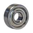
Another issue with the previous design was the bogie pivot (the pivot where the two legs are attached to) were not allowed to move freely. The issue was fixed by by using 2 ball bearing washers on each of the pivot points to allow this free movement.
Magnetic Rotary Encoder

The rotary encoders are currently not placed on the rover. The encoders that may be used are the vetco hall effect sensor module. Below is a 3D model of where the encoders will be placed as well as the sensor
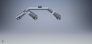
Modified Chassis Design Conclusion
The modified design was not tested. So to see if the modified design works, testing should be done before modifying or applying a new design. Assuming this modified design can work properly, there will still be an issue. This new issue which was discovered near the end of the mission was that the solar panel stepper motors will rest on the rod connectors that connect the legs to the bar. This may not cause any issues initially but it would be best that this issue be avoided. A fix for this would be using the previous design’s differential bar and extending the rovers legs out approximately an inch and half from its current position using longer  socket shoulder screws http://(https://goo.gl/wawpGJ . This design may have issues with having more force being applied onto the longer screw. So some stress testing may be required. An alternative design would be to completely get rid of the differential bar mechanism and opt in for a differential gear box mechanism. The following mechanism would have to be placed in between the battery and electrical box. Which will be an issue due to the battery being in the way of the connection points where the differential gear mechanism will be placed. So the battery may be required to be moved further back to allow this modification.

References

  1. https://docs.google.com/document/d/1NPQc2yRRpnUTUtxoxJKHqFgdvQKcfK46eKzEHFoKYcc/edit
  2. https://docs.google.com/presentation/d/18KhcQu9Qbvz87q95ofyxz0uMTzXnwRA5Ok51WPXzeXQ/edit

Electrical Box Setup

By Anthony Dunigan (Chassis – Design and Manufacturing Engineer)

The current cabling setup for the electrical box is shown below.

The box includes 3 VNH5019 motor shields that are stacked on top of each other. They are stacked to reduce the area that each individual driver  would have taken in the box. An additional hole was drilled into the box to allow more wires to enter the box which will decrease the risk of the wires being frayed or pinched from entering only one access point.

Fuse Protection

An inline fuse was incorporated into the box to protect the circuitry and battery. The previous semester did not incorporate this mechanism. The fuse can go hold up to 20 Amps. But only a 5 to 6 amp fuse will be required for protection. A fuse over 6 amps is not advised due to the max output of the battery being approximately 7 amps and will increase the risk of damaging the battery and circuits. As well as protecting the battery from exploding! The fuse was placed before the switch to protect the switch as well.

Terminal Block/Power Distribution

An 8 block terminal was used to distribute power and ground. The terminal block requires a ring terminal connector. Each ring terminal is red due to the classification of the wires gauge size (16 gauge). The power wires are red while the ground wires are black. 3 of the power lines coming from the output of the terminal block are going to the 3 motor driver shields. 1 wire is connected to the step down voltage regulator. The voltage regulator steps down the 12 Volts from the battery to 5 Volts. The output of the regulator is connected to a breadboard that should supply the arduino leonardo, servo motor, and ultrasonic sensors. Be sure to double check the voltage and current ratings  for all devices in the electrical box. The terminal block also has a custom polycarbonate glass protection on it. This should protect the terminal block from making contact with other electrical devices within the box.


Cabling Conclusion

The issue with current electrical box is that it is too small (7x5x3 cubic inches). A larger electrical box may be required to give sufficient room for all the required components that need to be placed. A larger electrical box will also allow you additional room just in case any additional components need to be placed inside such as the solar panel pcb and charge controller. The charge controller can have its own enclosure placed on the back side near the battery. But you must also consider the possible new mechanical design of the differential gearbox that may not allow the charge controller on the rear near the battery due to the new placement of the battery.

A smaller inline fuse may be used as well to increase the amount of room inside the electrical box. Additional fuses to be placed in line with the motor shields should be considered.

PCB

Schematic

By Renpeng Zhang

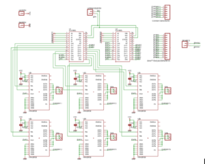
For the motor drivers and I2C expander, we decided to make it into a shield for Arduino. However, due to the size and number of the motor drivers; we weren’t able to put them into a single shield, so we decided to do two shields and stack them on top of the Arduino Leonardo. Due to the size of the heatsinks on the motor drivers, we have to design the shield in such a way where the top shield won’t cover up the motor drivers on the bottom shield. After careful considerations, we decided to put one PCA9685 I2C expander with three motor drivers on the first shield and the other PCA9685 I2C expander with the other three motor drivers on the second shield. The schematics for the two shield are identical except for the current sensing pins. The first shield utilizes the first 3 analog pins and the second shield utilizes the last 3 analog pins.

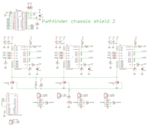
New design as a platform for Pololu VNH5019 dual motor drivers
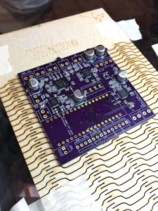
Solar PCB

Previous Semester’s PCB was assembled. Still needs cleaning up.
Chassis –  PCB Layout

By Anthony Dunigan (Chassis – Design and Manufacturing Engineer)
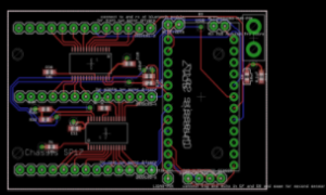
Without Polygon
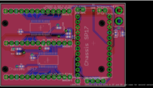
With Polygon


This is the completed or the most recently updated version of the custom PCB. This current version of the PCB will consist of 2 PCA9686 IC’s (I2C), multiple resistors and capacitors. The layout consist of 3 VNH5019 motor shield connectors. There will also be  arduino micro connectors, power pin connectors, lidars sensor connector, bluetooth connectors, and an alternate arduino pwr connector. This custom PCB will be using existing parts within the chassis. The existing parts are the motor shields and bluetooth. The additional parts needed will be the arduino micro. The PCB size is about 4 square inches. Includes holes for mounting the PCB.

Reference

  1. https://drive.google.com/open?id=0B9ZODu6tlNEcUnZkNWFUNWVKY3c
  2. From the Chassis_5_5 folder. File: Chassis_5_5D4.brd


Software

By Renpeng Zhang

General Software Flowchart
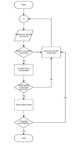
Rover control flowchart

Solar Panel State Flowchart
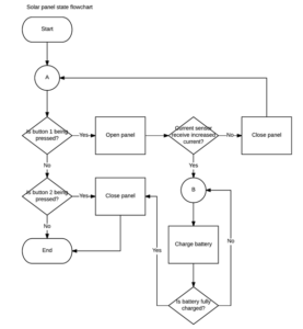
Verification Matrix

By Abdullah Albelbisi (Mission System and Test)

https://drive.google.com/open?id=0B3RM6QKrhjFIMzJsQkdUU0taOVE

https://drive.google.com/open?id=1xGVLvXXeleSxb98yUkLiqC7xg8m5uiotWOjMOk3OwaA

Project Documentation

Resource Report

By Everyone
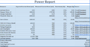
https://drive.google.com/open?id=1_Cagu3YueXAvwMQgK7jMg-9QrC4VUImQfjhPlNaiu9Y

Cost Report

By Everyone

https://drive.google.com/open?id=1_Cagu3YueXAvwMQgK7jMg-9QrC4VUImQfjhPlNaiu9Y

Schedule

By Martin Diaz (Project Manager)

The schedule was created using project Libre. The task were separated by division and then scheduled with the critical tasks in mind.

https://drive.google.com/open?id=0Bz6ZQqAMFyLHSG5tTl9rQm15Yk0

Burndown

By Martin Diaz (Project Manager)

The burndown was created by getting each task from the project Libre into excel and then assigning percent completion for each week.
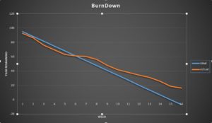
https://drive.google.com/open?id=0Bz6ZQqAMFyLHUThNWkgzQy1YdE0

Creativity

https://drive.google.com/open?id=104MTPy6nEF7KAQX6WpWLSnreQI6UHw2A80UVELk3wzg

PDR

https://drive.google.com/open?id=1vk9dVFMz31RVrXSXGV3NOuN1yaQoOdQNtvI5ly98sz8

CDR

https://drive.google.com/open?id=1soV0-mG75nks4ojD8DVIlJpCzfBcPZe9JpZQoynt9Ls

What We Learned From This Semester

By Martin Diaz (Project Manager)

One of the things I learned late in the semester was to ask the division for help. Don’t assume they won’t want to help you. The division managers can step in and help your project a lot and even get their engineers from other projects to help support your project.


Asking Professor Hill is also a lot of help. Especially with circuit design, schematics, and PCB layout.  We were having a lot of trouble trying to make our custom PCB on our own and then went to Prof. Hill for help. He said he enjoys circuit design and wished we had seen him sooner. If we had we would have completed our PCB in time.


One of the difficulties the group had was not be able do work on the project because one of the members had certain parts. I suggest getting similar parts from Prof. Hill so they can work on similar systems. For example you can 6 smaller motors and breadboard them to test your code instead of waiting for a chance to work on the actual motors you are going to use.


Project Video

https://drive.google.com/open?id=0B4jU8uMDmOoiYW52NWhSTVc1ZDg

Resources

EagleCAD Files – https://drive.google.com/open?id=0B_Kn5EG3fBjuejZyajBfYWVKWE0

Fritzing Files – https://drive.google.com/open?id=0B_Kn5EG3fBjuaURKRTBUR2M3QTA

Arduino Code – https://drive.google.com/open?id=0B_Kn5EG3fBjuMV9MZERvaENvUVE

Solar Design and Manufacturing Files – https://drive.google.com/open?id=0B4jU8uMDmOoiVVp5dkFRbC1jRTA

Chassis Design and Manufacturing Files – https://drive.google.com/drive/folders/0Bz6ZQqAMFyLHcXlsVm5lNUlIeXc?usp=sharing

Verification and Validation – https://drive.google.com/open?id=0B3RM6QKrhjFIR3JqcHZLRmVmUDA

Bill of Materials – https://docs.google.com/document/d/1fk77AdEc3pNCxLTQE3WCtPdG5hXLdYsb-yxXMa35l6k/edit?usp=sharing


HC-SR04 Ultrasonic Sensor Test

By Renpeng Zhang

HC-SR04 range test

Table of Contents

Table

Range HC-SR04 was tested

Code

/*

* HC-SR04 testing code

* Connect Vcc to 5V

* Connect Gnd to Gnd

* Connect Trig to pin 9(PWM)

* Connect Echo to pin 10(PWM)

*/


// defines pins numbers

const int trigPin=9;

const int echoPin=10;


// defines variables

long duration;

double distance;


void setup() {

 pinMode(trigPin, OUTPUT); // Sets the trigPin as an Output

 pinMode(echoPin, INPUT); // Sets the echoPin as an Input

 Serial.begin(9600); // Starts the serial communication

}

void loop() {

 // Clears the trigPin

 digitalWrite(trigPin, LOW);

 delayMicroseconds(2);

 // Sets the trigPin on HIGH state for 10 micro seconds

 digitalWrite(trigPin, HIGH);

 delayMicroseconds(10);

 digitalWrite(trigPin, LOW);

 // Reads the echoPin, returns the sound wave travel time in microseconds

 duration=pulseIn(echoPin, HIGH);

 // Calculating the distance

 distance=duration*.034/2-1;

 // the -1 is to factor in the error of my specific sensor and put it into consideration

 // Prints the distance on the Serial Monitor

 Serial.print(“Distance: “);

 Serial.print(distance);

 Serial.println(” cm”);

 delay(500);

}

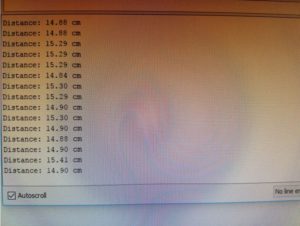
Output

Source

http://howtomechatronics.com/tutorials/arduino/ultrasonic-sensor-hc-sr04/


Schematic

By Renpeng Zhang

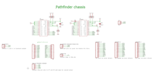
Chassis Schematic

Schematic

Description

For the chassis eagle schematic, I choose to use two PCA9685 I2C expanders because one doesn’t have enough PWM pins for all our needs. We also used six VNH2SP30 motor driver for our motors. We use the PWM input from the I2C to the PWM pin in the motor driver. We left the shaft encoder pins on the second expander for the reading of the values for the RPM of the motor. We have left the pins for the current sensing on each of the motor driver so that they will be connected to the analog input of the Arduino to get the current of each motor.