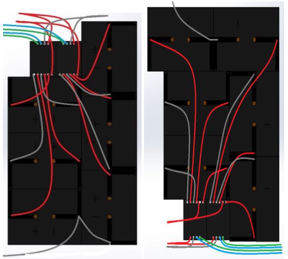
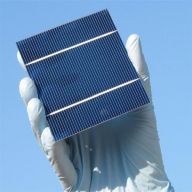
Solar Cell Wire Layout
By Edgardo Villalobos
Wire layout out for the solar panels.
Table of Contents
Top View

Bottom of panels
1.
2.

3.

Top Level


By Edgardo Villalobos
Wire layout out for the solar panels.
Table of Contents

By Anthony Dunigan
Back of the envelope calculations for wheels and electronic slip differential.
Table of Contents
In order for the project to move forward in our Level 2 requirements numbers 8 and 9. We need to gather calculations based on our 6 in (0.0762m) wheel diamater.
r = radius (m), m = mass (kg), g = acceleration of gravity (m/s2), u = dynamic friction coefficient, uo = static coefficient, F = normal force(N), Fpw = normal force per wheel(N), FNet = net force or tangential force(N), Fstatic = static friction force(N), Fdynamic = dynamic friction force or when the wheel slips(N), T = torque(N*m), M = motor torque(N*m), Ff = friction force(N), I = current (Amps), V = voltage (Volts), Pout = Output power of motor (W), Pin = input power of motor;
m = 22kg; g = 9.8 m/s2 ; u = 0.725 (rubber on concrete); uo = 1 to 4 or 2 (rubber on concrete); M = 0.339 N*m, I = 1.96 A, Pout = 9.3 W , at max efficiency; M = 1.13 when stalled.
F = m*g = 22kg *9.8 m/s2 = 215.6 Newtons (N), Fpw = F/6 = 35.93 N;
For the wheels to be balanced, static friction force must fulfill this inequations:
Fstatic ≤ uo * Fpw = (2) *35.933 N = 71.866 N;
If the static friction is unable to balance the system, then the static friction becomes dynamic friction and that’s when the wheel slips. The dynamic friction equation is:
Fdynamic = u * Fpw = 0.725 * 35.933 = 26.05 N;
For the wheel to avoid any slip, the friction force which is dependent upon the motor torque (M) should satisfy the equation below:
Ff = M/R ≤ uo * Fpw
Ff = 0.339 (N*m)/0.0762(m) = 4.45 N
So the force acting on the wheels must not be greater or equal to the friction force of the motor.
Sources
http://e-collection.library.ethz.ch/eserv/eth:8200/eth-8200-01.pdf
http://hypertextbook.com/facts/2006/MatthewMichaels.shtml
http://simplemotor.com/calculations/
http://www.tsinymotor.com/cn/Products/wolunjiansudianji/2014/0619/118.html
(Written By: Edgardo Villalobos – Manufacturing/Solar Panel)
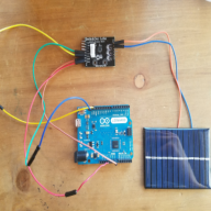
Using INA3221 current sensor breakout boards to measure current and voltage of a battery. INA3221 current sensors will be implemented in project to isolate voltage of each solar cells.
Table of Contents
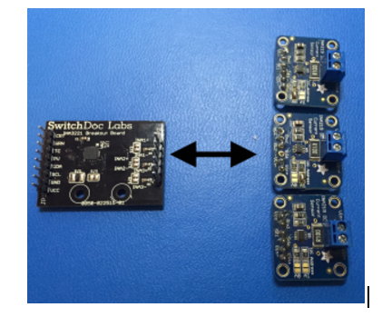
This project requires current sensors in order to measure the current running through the solar cells. We are having 36 solar cells on the solar panel. We are using 12 INA3221 current sensor breakout boards to do this because they each contain 3-channels, support high-side current and bus voltage monitors with an I2C interface. These sensors are able to connect to the Arduino we will be using.


In the photo below, there is only one channel being used. The voltage is only measured because to measure the current, the circuit requires a load.


The Arduino code for the current sensors is shown below for one channel. It defines the channels and names, sets all values to zero, reads the input values, and finally gives out the outputs for each of the channels being used.


For practice, a battery and a resistor were used to find the voltage and current. The battery is the voltage source and the resistor acts as the load. The current sensor was able to record both current and voltage.


By Renpeng Zhang
Demoing control of a stepper motor.
Table of Contents
In this demo, I tested the 28BYJ-48 stepper motor with the ULN2003 stepper motor driver. I used one Arduino for the control of the stepper motor. Since it’s recommended to use an external power source, I just used another Arduino solely for the purpose of providing 5V DC to the motor driver. I was able to control the stepper motor to do rotate clockwise and counter clockwise.

Arduino code:
/*
* 28BYJ48 stepper motor code
* Connect:
* IN1>>D8
* IN2>>D9
* IN3>>D10
* IN4>>D11
* Vcc 5V source, prefered external 5V source
* Gnd
*/
#define IN1 8
#define IN2 9
#define IN3 10
#define IN4 11
int Steps=0;
boolean Direction=true;// gre
unsigned long last_time;
unsigned long currentMillis;
int steps_left=4095;
long time;
void setup() {
Serial.begin(115200);
pinMode(IN1, OUTPUT);
pinMode(IN2, OUTPUT);
pinMode(IN3, OUTPUT);
pinMode(IN4, OUTPUT);
// delay(1000);
}
void loop() {
while(steps_left>0){
currentMillis = micros();
if(currentMillis-last_time>=1000){
stepper(1);
time=time+micros()-last_time;
last_time=micros();
steps_left–;
}
}
Serial.println(time);
Serial.println(“Wait…!”);
delay(2000);
Direction=!Direction;
steps_left=4095;
}
void stepper(int xw){
for (int x=0;x<xw;x++){
switch(Steps){
case 0:
digitalWrite(IN1, LOW);
digitalWrite(IN2, LOW);
digitalWrite(IN3, LOW);
digitalWrite(IN4, HIGH);
break;
case 1:
digitalWrite(IN1, LOW);
digitalWrite(IN2, LOW);
digitalWrite(IN3, HIGH);
digitalWrite(IN4, HIGH);
break;
case 2:
digitalWrite(IN1, LOW);
digitalWrite(IN2, LOW);
digitalWrite(IN3, HIGH);
digitalWrite(IN4, LOW);
break;
case 3:
digitalWrite(IN1, LOW);
digitalWrite(IN2, HIGH);
digitalWrite(IN3, HIGH);
digitalWrite(IN4, LOW);
break;
case 4:
digitalWrite(IN1, LOW);
digitalWrite(IN2, HIGH);
digitalWrite(IN3, LOW);
digitalWrite(IN4, LOW);
break;
case 5:
digitalWrite(IN1, HIGH);
digitalWrite(IN2, HIGH);
digitalWrite(IN3, LOW);
digitalWrite(IN4, LOW);
break;
case 6:
digitalWrite(IN1, HIGH);
digitalWrite(IN2, LOW);
digitalWrite(IN3, LOW);
digitalWrite(IN4, LOW);
break;
case 7:
digitalWrite(IN1, HIGH);
digitalWrite(IN2, LOW);
digitalWrite(IN3, LOW);
digitalWrite(IN4, HIGH);
break;
default:
digitalWrite(IN1, LOW);
digitalWrite(IN2, LOW);
digitalWrite(IN3, LOW);
digitalWrite(IN4, LOW);
break;
}
SetDirection();
}
}
void SetDirection(){
if(Direction==1){Steps++;}
if(Direction==0){Steps–;}
if(Steps>7){Steps=0;}
if(Steps<0){Steps=7;}
}

By Edgardo Villalobos
Calculations to find what voltage and current the solar cells need to provide to charge the battery in 8 hours.
Table of Contents
Rule of thumb: Solar Panel Voltage = Battery Voltage x 1.5
Solar Panel Voltage = 12-V x 1.5
Solar Panel Voltage = 18-V
Rule of thumb: Amps = Amp Hours / Hours
Amps = 7-Ah / 8-hrs Amps = 10-Ah / 8-hrs
Amps = 875-mA Amps = 1.25-A
By Edgardo Villalobos
Study on types of solar cell encapsulation.
Table of Contents
Plexiglass provides a lightweight, about 3 lbs per 8 sq. ft. with a 0.065 thickness, anti-reflective surface and is classified as a scratch resistant surface. Although plexiglass is virtually impossible to break and scratch resistant, it can scratch much easier than glass. If this material is used to encapsulate solar cells, we’d be able to acquire it from Home Depot or other similar store. This glass would then be used to cover the entire panel. To get the right shape out of the glass, we could use a dremel grinder to cut to size. The size of the glass would be the same size as the panels, which still need to be measured. The downside to using plexiglass is that each solar cell needs to be sandwiched using other materials, such as resin, which costs more.


[1]Plexiglass
[2]Materials
[3]Materials
http://www.dunmore.com/products/solar-back-sheet.html
Solar cells could be bought already encapsulated with a UV resistant epoxy and are usually meant to charge phones. Each cell is independently encapsulated making it easier to remove and add new cells. These cells are also polarity based, which could require wires instead of tabbing wires, also making it easier to switch cells. Using these cells would cost about the same as buying all the materials, using the plexiglass sandwich method.


[1]Array
http://www.samlexsolar.com/learning-center/solar-cell-module-array.aspx
By Renpeng Zhang
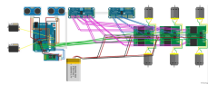
Fritzing Diagram for Chassis.
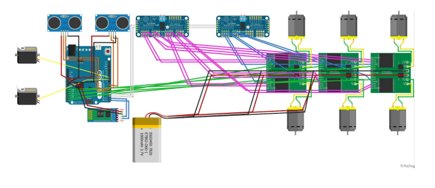
Based on the interface definition, I created the fritzing diagram for the chassis part of the pathfinder. It consists of the Arduino Leonardo with two HC-SR04 ultrasonic sensors. It has the HC-05 bluetooth module connected to the Arduino through the TX and RX pins for the communication through a phone using the Arxterra app. Two servos is connected to the Arduino for the control of the pan and tilt of the rover. Two PCA9685 I2C expander were used for extra digital PWM and analog input pins. The VNH2SP30 motor driver is connected to the I2C expander and it’s used to control the speed of the motors. The built in current sensor of the motor driver is connected to the analog input of the Arduino for the monitoring of the current going through each motor. Battery was connected to power the motor drivers.
By Edgardo Villalobos
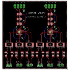
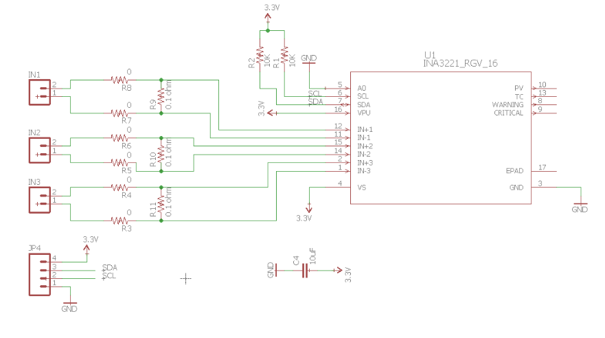
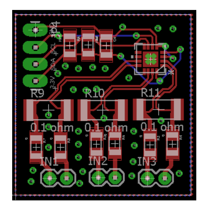
Custom PCB created by combining two INA3221 into one board.
Table of Contents

Three INA219 = One INA3221
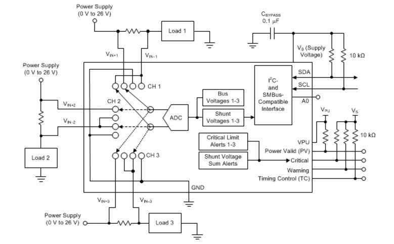
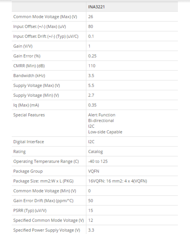
The INA3221 is a three-channel, high-side current and bus voltage monitor. It contains the setup of 3 INA219 single-channel, high-side current and bus voltage monitor.

The solar panel on the pathfinder rover contains 6 different panels with 6 solar cells on each panel that are setup in a certain way in series and parallel to get an output of 18 volts and 200 milliAmp from each of the panels to get a total of 18 volts and 1 amps. To test the current flowing through each of the 36 cells, we are going to use the INA3221 current sensor. As described in the INA3221 datasheet, this sensor senses current on buses that can vary from 0V to 26V. Because the INA3221 is three channels, it only measures the current running through 3 inputs, meaning we’ll need 2 per panel. The original Eagle CAD PCB layout was modified in order to get a total of six inputs that will match up perfectly with the 6 cells on each panel, meaning we will only need 6 boards as opposed to 12.
Since the these sensors can only have 4 addresses, I2C multiplexers are required.
http://www.ti.com/product/INA3221/description
http://www.ti.com/lit/ds/symlink/ina3221.pdf
http://www.ti.com/lit/ds/symlink/ina219.pdf
http://www.switchdoc.com/wp-content/uploads/2015/04/INA3221BOB-042015-V1.0.pdf
https://drive.google.com/drive/folders/0B4jU8uMDmOoiU1dOM0tzSU1qeHM