Fall 2016 Solar Panels: Software Block Diagram Update

By Stephan Khamis (Mission, Systems, and Test)

Approved by Inna Echual (Project Manager)

Table of Contents

Introduction

This blog post contains our most up-to-date software block diagram  (SBD) for the Solar Panel system of the Pathfinder project. Within this blog post you will learn about the changes we have made since the CDR to update this diagram to reflect our design.

Previous Software Block Diagram

sbd_cdr

Figure 1: Software Block Diagram Presented During CDR

The software block diagram the group presented during our CDR presentation is shown in Figure 1. The group received feedback from the Missions, System, and Test division manager, president, and the customer that the SBD lacked details of our system and was missing key parts of our software design. As a result, the necessary changes were made to define our current Software Block Diagram.

Updated Software Block Diagram
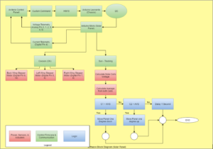
screen-shot-2016-12-16-at-2-20-18-pmFigure 2: Updated Software Block Diagram

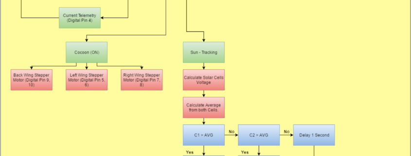
The software block diagram in Figure 2 is the aforementioned update and it explains an overall understanding of what the Solar Panel systems software entails. It also includes a portion of the Chassis system and how we are interfacing with one another electronically, along with a legend on the bottom left to help detect what the different colors mean.

The Arduino Leonardo from the Chassis will be set as the master and connected to the Arxterra Control Panel. The Arduino Micro from our system will be set as the slave. The roles of each Arduino is as follows: the Chassis system will be sending the Solar Panel system custom commands (cocooning) and an autonomous command (sun-tracking). This will be done through an HM-10 BLE Bluetooth to an Android phone provided by the Chassis group. While the Chassis group is supplying us with Commands, we will then be supplying the Chassis with custom telemetry, such as current and voltage readings. The current readings will be provided from a current sensor that is pinned to digital pin 4 on the Arduino Micro. The solar cells will provide the voltage telemetry. This is done by connecting the solar cells outputs to Analog Pins 0, 1, 2, 3, 4, and 5.

Furthermore, the commands for the Solar Panels will be heavily communicating with the stepper motors. As you can see above, when the Cocoon command is switched on, it will then activate all three stepper motors. These stepper motors are connected to Digital Pins 5 and 6 for the left wing, Digital Pins 7 and 8 for the right wing, and Digital Pins 9 and 10 for the back wing.

The Sun – Tracking command, is autonomous and will always be running through a loop that is explained within the diagram. In simple terms, the program will compare the voltage readings through the solar cells on the left and right wings. For the wing with the greater voltage, the wings will then adjust itself to that direction of the sun.

Future Updates

As of now, there are no future updates that I plan to change within the now updated Software Block Diagram.

References

[1] Arduino MICRO and Genuino MICRO Reference: https://www.arduino.cc/en/Main/ArduinoBoardMicro

[2] Arduino Leonardo: https://www.arduino.cc/en/Main/ArduinoBoardLeonardo

[3] Fall 2016 Solar Panels: 12C Communication Experiement: http://arxterra.com/fall-2016-solar-panels-i2c-communication-experiment/

Experiment: LiDAR Lite

By Jose Alcantar, Electronics and Controls Engineer

Introduction

The LIDAR is a laser range finder which can measure distances of up to 40 meters with an accuracy of ­­±2.5 cm. The device can be used via I2C interface or through pulse width modulation. The LIDAR is to be implemented onto the pathfinder for the use of obstacle detection and avoidance requirement.

Wiring Diagram:


picture6

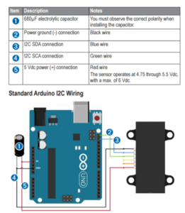
For testing purposes the LIDAR was wired as shown by the wiring diagram. An Arduino Uno was used using the SCL and SDA I2C pins.

Purpose:

The purpose of this experiment is to calculate and test the field of view of the LIDAR sensor and to test sunlight interference.

Procedure:

An object was placed 0.5 meters away and directly in front of the sensor. The center point of the object was marked and moved in increments of about 0.5 cm to the left until the sensor no longer detected the object. This point was marked and the object was once again replaced to the center and moved in increments of 0.5 cm to the right of the sensor. When the sensor no longer detected the object, the position was marked. The beam diameter was calculated based on the distance between the two points. Using the same method, the experiment was repeated at 1 meter then 1.5 meters.

The LIDAR was tested outside in sunlit conditions to observe the interference of sunlight on the sensor. The sensor was pointed at various objects and the data was observed for any interference.

Results:

The beam diameter was calculated for each of the test runs. At 0.5 meters, the diameter of the beam was well within the mm range. At this distance, the diameter of the beam was about 15 mm. At 1 meter, the calculated beam diameter was about 16 mm. At 1.5 meters, the diameter of the beam was about 2 cm.

Using the LIDAR outside showed no obvious interference. Although, pointing the sensor at different objects with various reflectivity did have some effect on the data. The sensor did have less accurate results on objects with more reflective surfaces.

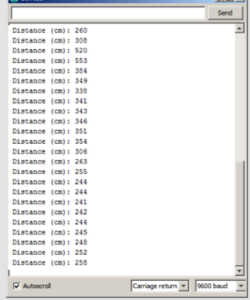
The following table is an example of the output from the serial port on Arduino IDE.

picture7

Heading and GPS Coordinates Formatting

By Jose Alcantar, E&C Engineer

picture4Introduction:

The GPS information received through the Arxterra control panel can be sent through three different data types. The first data type is a 32-bit floating point, the second is a 64-bit floating point or “double” and lastly a 32-bit integer or “long”. Depending on how the settings are configured through the “Robot Capabilities Configuration” menu in the app, the user can choose between any of these three data types. For further information on the data types see the blogpost by Jeff Gomes,

https://www.arxterra.com/arxterra-now-supports-waypoint-navigation/

For our purpose, the 32-bit integer was selected as the data type due to some formatting issues when using the 32-bit floating or 64-bit floating types.

To begin with formatting the coordinates, it must first be understood what values are being sent through the Arxterra app. From the link above, Gomes explains that for the 32-bit integer the units are set to decimicrodegrees. This means that for example, coordinates 33.794904, -117.913712 would be encoded as 33794904, -117913712. The app sends the coordinate values through a 16-byte packet, in which the first 4 bytes are the latitude and the last 4 bytes are the longitude coordinates, bytes being represented in hexadecimal.

picture3

There are different commands available related to GPS navigation, further described in this link,

https://www.arxterra.com/pathfinder-arxterra-communication-commands/

Example:

The following firmware code is based on the WAYPOINT _COORD command, which is used to receive the waypoint coordinate packet data and to format the coordinates into usable values.

After a waypoint is created, for example, 33.794904, -117.124567, the app converts these values into decimicrodegrees and sends the values to the MCU as a 32-bit long. The data being sent will be as follows

{A5, 10 (packetlength),14 (command id), 02 03 AB 58 F9 04 D6 80, (checksum)};

picture4

To extract the data through the Arduino some variables must first be declared:

long waypointLat4;

long waypointLat3;

long waypointLat2;

long waypointLat1;

unsigned long waypointLat;


long waypointLon4;

long waypointLon3;

long waypointLon2;

long waypointLon1;

unsigned long waypointLon;


The byte vales are extracted from the packet and the bits are shifted to be stored into a 32-bit unsigned long.

void waypoint_coordHandler (uint8_t cmd, uint8_t param[], uint8_t n)

{

waypointLat4 = param[0];

waypointLat3 = param[1];

waypointLat2 = param[2];

waypointLat1 = param[3];

waypointLat = (waypointLat4 << 24 | waypointLat3 << 16| waypointLat2 << 8| waypointLat1);


waypointLon4 = param[4];

waypointLon3 = param[5];

waypointLon2 = param[6];

waypointLon1 = param[7];

waypointLon = (waypointLon4 << 24 | waypointLon3 << 16| waypointLon2 <<                  8| waypointLon1);

waypointLon = ~waypointLon;

waypointLon = (waypointLon + 1) * -1;

}

The longitude coordinates require a secondary step to get the right value. Because longitude is a negative value, a 2’s complement operation must be done on the final value to get the right coordinate. Using this formatting, successfully converts the packet data being sent into usable coordinates needed for GPS navigation.

Conclusion:

Following this method, the GPS data sent through the Arxterra control panel can be converted into usable values, which will help with autonomous navigation.

Resources:

https://www.arduino.cc/en/Reference/Bitshift

https://www.arduino.cc/en/Reference/UnsignedLong

https://www.arduino.cc/en/Reference/Long

https://en.wikipedia.org/wiki/Two’s_complement


Implementing MOVE Command Firmware

By Jose Alcantar, Electronics and Controls Engineer

Introduction:

The pathfinder is controlled using the direction pad on both the control panel and through RC mode on the Arxterra app. When using the D-pad, the MOVE command is called from the 3Dotlibrary which is used to control the movement of the motors. Through the design of the 3Dotlibrary, pins 5,6,10 and 13 on the Arduino Leonardo are tied to the MOVE command. Because of how are system is designed, firmware was written to take advantage of the data from the D-pad and MOVE command, without using the dedicated pins.

When a button is pressed on the D-pad a packet is sent through Bluetooth and is decoded by the Arduino. The packet data is sent in the following format:

{A5,  (packetlength), 01 (command id), 01 80 01 80, (checksum)};

The first value after the command id specifies the direction for the left set of wheels on the pathfinder followed by the second byte which is the PWM value to control the speed of those motors. The last next two bytes are used to control the right set of motors.

The following is a brief description of how the index values are interpreted


/***********************************

* motion command = 0x01

* motordata[3]   left run    (FORWARD = index 1, BACKWARD = index 2,

BRAKE =   index 3, RELEASE = index 4)

* motordata[4]   left speed  0 – 255

* motordata[5]   right run   (FORWARD, BACKWARD, BRAKE, RELEASE)

* motordata[6]   right speed 0 – 255

* example

* forward half speed  0x01, 0x01, 0x80, 0x01, 0x80 0101800180

***********************************/


Firmware:

Understanding the data being sent from the D-pad, firmware was written for the motor controls. A series of if-else statements were used to account for the different data packets that the Arxterra app transmits:


void moveHandler (uint8_t cmd, uint8_t param[], uint8_t n)

{

Serial.write(cmd);             // move command = 0x01

Serial.write(n);               // number of param = 4

for (int i=0;i<n;i++)          // param = 01 80 01 80

{

Serial.write (param[i]);

}


if(param[0] == 1 && param[2] == 1)

{

input_pwm1 = param[1];

input_pwm2 = param[3];

left_forward();

right_forward();


}

else if( param[0] == 2 && param[2] == 2)

{

input_pwm1 = param[1];

input_pwm2 = param[3];

left_reverse();

right_reverse();

}

else if( param[0] == 1 && param[2] == 2)

{

input_pwm1 = param[1];

input_pwm2 = param[3];

right_turn();

}

else if(param[0] == 2 && param[2] == 1)

{

input_pwm1 = param[1];

input_pwm2 = param[3];

left_turn();

}

else if( param[0] == 1 && param[2] == 4)

{

input_pwm1 = param[1];

input_pwm2 = param[3];

left_forward();

right_release();

}

else if(param[0] == 2 && param[2] == 4)

{

input_pwm1 = param[1];

input_pwm2 = param[3];

left_forward();

right_release();

}

else if(param[0] == 4 && param[2] == 1)

{

input_pwm1 = param[1];

input_pwm2 = param[3];

left_release();

right_forward();

}

else if(param[0] == 4 && param[2] == 2)

{

input_pwm1 = param[1];

input_pwm2 = param[3];

left_release();

right_reverse();

}

else if(param[0] == 4 && param[2] == 4)

{

input_pwm1 = param[1];

input_pwm2 = param[3];

left_release();

right_release();

}


Conclusion:

Following this code format, the motors can be controlled to move forward, reverse, brake, and release. Depending on the values being transmitted, the functions to drive the motors are called. The PWM values are then extracted from the packet and stored onto a variable to control the speed.

Motor Control Interface

By Jose Alcantar, Electronics and Controls Engineer

Introduction:

To drive the six motors independently as per requirement, 3 dual motor drivers are being utilized. Three VNH5019 motor drivers will be used to control each motor along with a PCA96805 I/O expander and a hex inverter.

VNH5019:

The VNH5019 dual motor driver requires three pins to control each of the two H-Bridges integrated onto the board. The two-motor direction pins (M1INA and M1INB) for the first H-Bridge use a digital output high and low to set the direction of the motor. The following truth table summarizes the different settings for the pins:

picture2

For example, to drive the motor clockwise M1INA is set high, while M1INB is set low. To reverse the direction M1INA is set low and M1INB is set high.

The third pin (M1PWM) is used to control the speed of the motor via a PWM signal.

The pathfinder will utilize three VNH5019 dual motor driver boards, with each board requiring 6 pins to control each motor. This gives us a total of 18 pins needed to control the motors. Due to the limitation of pins on the Arduino Leonardo, a PCA9685 16-channel 12-bit I/O expander along with a hex inverter will be used to control each of these pins.

PCA9685 & 74HC04 Hex Inverter:

The PCA9685 I/O expander allows the user to expand the capabilities of the Arduino by providing an additional 16 channels through I2C interface. Six of these channels will be dedicated for controlling the PWM input of all six H-Bridges. The PCA9685 has a dedicated library available that simplifies the use of the board. The following sample code shows how to set the output of one of these channels.

pwm.setPWM(0, 0, 4095);   //Sets the output to 100% duty cycle

In the above sample code the first input is the channel output pin, followed by the off time for the duty cycle and finally, the last value is the on-time for the duty cycle. Because the board has 12-bit resolution, the values for the duty cycle range between (0 – 4095), giving 4096 steps.

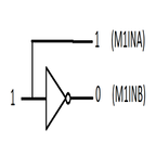
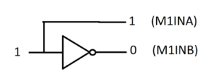
To control the motor direction, the use of a Hex inverter along with the I/O expander will be used to reduce the number of pins being utilized. Using an inverter, the motor direction can be controlled clockwise and counterclockwise with the use of a single pin. The following diagram shows the basic idea of how the direction will be determined.

picture1

In this case, setting the channel output HIGH or 100% duty cycle on the I/O expander, will set the direction pin M1INA high and M1INB low, driving the motor in the clockwise direction. Setting the channel output LOW, or 0% duty cycle, will do the opposite.

Conclusion:

With this configuration, the 18 pins needed to drive the motors is reduced to only 12 pins from the I/O expander. This leaves four more pins on the expander to drive servos or other actuators.


Fall 2016 Solar Panels: Creating a Port Expander Using IC MCP23017

By Jose Rodriguez (Electronics & Control)

Approved By Inna Echual (Project Manager)

Objective: Because of our current design, a port expander is needed because there are no more available pins on our Arduino to read data from the reed switches. The reed switches will be used to halt the panels from cocooning more than it needs to; if it goes past a certain angle, it could hit the adjacent panel and damage its cells.

How to Set Up the IC

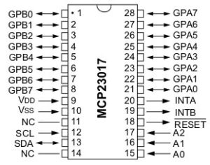
The Microchip MCP23017 is a 16-bit serial expander with I2C serial interface. This 28-pin IC offers sixteen inputs or outputs. Figure 1 shows the pinout data sheet for the IC:

mcp23017datasheet

Figure 1: MCP23017 Pinout [1]

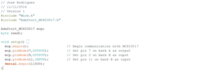
Firstly, the expander was checked to see if it worked using two LEDs, which will be set high and low using the IC. Note that there are two banks, A and B, and each bank has a total of 8 pins. Both banks will be used in this blog to understand either or both of their activations.

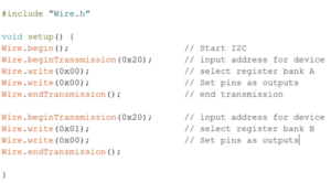
The code in Figure 2 is used to set up ports as outputs. The address for the device can be found on the data sheet [2], but to save time it is x20. To set pins as input, a one need to be set on the fourth column of the code depending on the required pin. Hex values are used, so for example, FF will set all pins as inputs. F0 sets the first 4 pins as inputs and the last 4 pins as outputs.

exp_code1

Figure 2: Code to Set Up Input and Output Ports

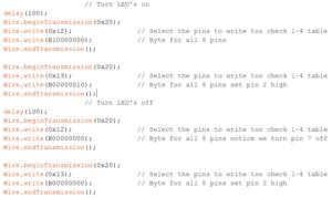
Once setup is complete, it becomes simple to set ports as high or low. The code in Figure 3 shows how to set up the pins using binary values. Four lines of code are needed to write on pins. The code takes a lot of space but there is a library that has been made for the MCP23017 by Adafruit that adds 1,000 bytes of memory.

exp_code2

Figure 3: Code to Set up Pins

The Adafruit library needs to be downloaded and saved in the Arduino library because it can be used with the IC. The code for using the library is shown in Figure 4. First the Adafruit library has to be included by writing #include. The code from Adafruit is similar to that of the Arduino when it comes to setting up pins, but mcp. needs to be added before pinMode. The setup is straight forward however note that Bank b refers to pins 8 to 15.

exp_code3

Figure 4: Code to Use Adafruit Library

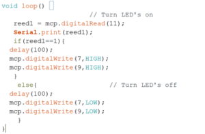
Alternatively, the following code in Figure 5 turns two led on and off, but is more efficient as it requires less code. Either method can be used but the latter is cleaner than the other. If memory code is an issue, then the longer method (firts code) will be optimal to save memory.

exp_code5

Figure 5: Alternative Code to Light LEDs

Conclusion

Adding a port expander is not as hard as one will think as using the Adafruit library makes the process even easier. To read a pin the command that will be needed is mcp.digitalRead only. The second method makes the code cleaner, but the first method gives an individual an idea of what is going on behind the second method.

References

[1] Maximising your Arduino’s I/O ports with MCP23017: http://tronixstuff.com/2011/08/26/tutorial-maximising-your-arduinos-io-ports/

[2] MCP23017 Data Sheet: http://ww1.microchip.com/downloads/en/DeviceDoc/21952b.pdf


Fall 2016 Solar Panels: Choosing Panel Thickness (Stress Tests)

By Ridwan Maassarani (Design & Manufacturing)

Edited and Approved By Inna Echual (Project Manager)

Objective: The thickness of our panels must be carefully chosen as “too large” of a thickness could result in additional weight, possibly causing unnecessary strain and bending. Though the chassis could withstand our panels weight a maximum 50 lbs (as stated by the chassis group), we would like to chose a weight that would minimize bending as bending could cause our solar cells to break due to their delicate state.

Choosing Optimal Thickness

The thickness of the panels should be chosen so that it can carry its own weight under the force of gravity, as well as be well below the maximum 50 lbs. load requirement set by the chassis group. Cutting various panel configuration numerous times using varying aluminum thicknesses would take a long time and waste expensive material, the stress analysis tool feature in SolidWorks was used.

solarpanels

Figure 1: Panel Reference

The panel being evaluated is the butt panel (see Figure 1). The stress analysis tool was used on the butt panel to verify that it wouldn’t bend under the force of gravity.

The first step is to define a location where the object being tested will not move. In my case, it is three mounting holes for the hinge. Gravity acting on the top of the back panel was defined as the load. Using the mass properties tool under evaluate in SolidWorks, the approximate mass of the back panel was obtained to be 383.93 grams.

Note that the additional of the cells, rubber sheets, and glass will increase the weight; to remedy this, the weight of a single cell was measured and multiplied with the amount of cells that can fit onto the back panel.

whatsapp-image-2016-12-05-at-8-50-21-pm

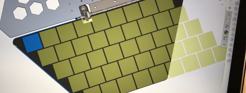
Figure 2: Solar Cell Arrangement on Butt Panel

Currently, 33 cells can fit on the butt panel comfortably with 2mm spacing between them (also taking into account panel cutouts for the gears, see Figure 2 above). The weight of one cell was measured to be 0.75 grams so an approximate addition of 24.75 grams is added due to cells. Masses pertaining to the solder and copper tape is negligible but the cell system was rounded to 30 grams.

The total mass was converted to Newtons, which was entered into one of the SimulationXpress analysis wizard. Since aluminum was determined to be the material of our panels, it was selected in the design.

untitledkkk

Figure 3: Butt Panel Displacement using 3.175mm Aluminum

Figure 3 shows the displacement acting on the panel. An eDrawing file can be saved once the results have been calculated. Furthermore, the tool can be used to optimize the design. For example, it allows the user to change dimension right and set goals to meet the customer’s needs. SolidWorks will calculate multiple scenarios to meet specific goals.

main to butt

Table 1: Base to Butt Panel Deflection Data

tavble1

Graph 1: Thickness (mm) vs. Deflection (mm) of Butt Panel

Data concerning deflection was generated and inputted on Excel in order to determine panel thickness unacceptable deflection is seen. Table 1 shows the deflection from the base panel to the butt panel. The relationship between the varying thicknesses and resulting deflection is shown in Graph 1. The x-axis shows different thicknesses of 6061-T6 aluminum in millimeters and the y-axis represents the deflection distance in millimeters.

The four side panels (left front, left back, right front, right back) are similar in size and weight so the same stress analysis was done on the deflection between the base panel and the right front panel. Figure 4 shows the displacement acting on the aforementioned panel.

untitled

Figure 4: Right Front Panel Displacement using 3.175mm Aluminum

Figure 4 shows the deflection between the base and right front panel. Table 2 and Graph 2 contain the data on the relationship between thickness and deflection distance, as done with the butt panel.

Conclusion

Based on the data, we were able to determine that 1.25 in (3.175 mm) is the optimal thickness our aluminum should be to minimize bending. Our motors will be able to handle this weight and the total weight (including the addition of cells, wires, glass, motors, etc.) is still under the weight restriction of 50 lbs as set by the chassis group.

Fall 2016 Solar Panels: I2C Communication Experiment

By Jose Rodriguez (Electronics & Control)

Approved By Inna Echual (Project Manager)

Objective: Currently, we will be using our own Arduino Leonardo while the Thursday Pathfinder group (referred to as the chassis group) will also have their own Arduino Leonardo. The solar panels Arduino and chassis Arduino will communicate using I2C interface on Arduino. In order to ensure the concept is understood completely, the following experiment was done with an Arduino Mega and Arduino Uno, where the Mega was used as the Master and the Uno as the slave.

The following were the components used for the experiment:

  • Arduino Uno
  • Arduino Mega
  • LED
  • Resistor
  • Breadboard

untitled1

Figure 1: Code to set up Mega as master

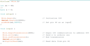
The code in Figure 1 was used to set up the Arduino Mega as the master. The serial monitor was used to debug the system; however it can be removed without affecting the code. Wire.Begin starts the communication using the I2C and address must be inputted. Wire, write is then used to send data to the Arduino. To end the communication using the I2C, Wire.endtransmission needs to be used.

 untitled3

Figure 2: Code to set up Uno as slave


The code in Figure 2  was used to set the Arduino Uno as the slave. The key difference is that the Arduino is given an address by writing wire.begin followed with address. The address given to the Arduino is 400 because of the class but any number could have been used. In addition, a subroutine has to be made so that when data is sent, the Arduino goes to the function and does something with the data received. Note that the function called cocoon was created but any other function can be used.

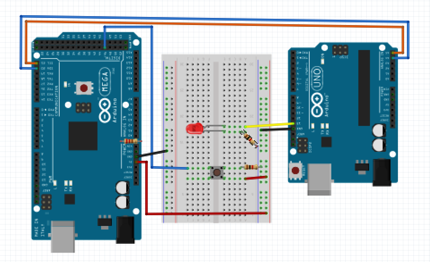
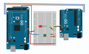
Figure 3 shows the Fritzing Diagram showing how the circuit is configured.

untitled4

Figure 3: Fritzing Diagram

untitled5

Figure 4: Visual Results of Experiment

Figure 4 shows the results of our experiment, i.e. our code working: every time the button is pressed, the Arduino Mega reads the value and sends the value to the Arduino Uno. As a result, pin 13 is set to high whenever the value received is one. Since we do not have both projects done yet, I am using the button as the Arxterra signal that will tell Arduino mega to cocoon. A LED on means subroutine cocoon is active in the Arduino Uno and inactive if the LED is off.

This experiment verifies that communication between two Arduinos is possible.


Current Sensors Experiment

Current Sensing Experiment:

Purpose:

Measuring motor draw current on current sensing pins via the VNH5019 to identify no load conditions and determine no-load threshold to shut off motors.

The VNH5019 provides two current pins to the user, which can be used to measure the instantaneous current absorption by each H-Bridge.

Procedure:

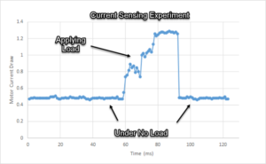
While running a motor through the VNH5019, the current was measured using the Arduino Leonardo via the current sensing pins M1CS and M2CS. Through software, a running average smoothing filter was used to remove inconsistencies in the data. After graphing the current data drawn by the averagre, a threshold was determined. An ammeter was attached to the motor to directly compare the current measured with the Arduino data.

Results:

After reading the current measured by the Arduino, a current range was determined at which the motor ran under no load conditions. From the data, it was determined that under no load conditions, the current draw was between 450 mA and 600 mA. Using the Ammeter as a reference, it was found that the actual current draw of the motor was about 620 mA. The threshold for the current under no load conditions was chosen to be 620 mA.

picture3

Digital Slip Differential Voltage Ratio

By: Jose Alcantar, Electronics and Controls Engineer

Speed Ratio Calculation for slip differential

Purpose:

To implement slip differential turning, the speed ratio for the left and right set of wheels needs to be calculated. Further testing needs to be done to find a comfortable speed for the left and right wheels.

Procedure:

To determine the speed ratio, the distance each wheel travels was calculated. This ratio can then be applied to both the speed and the voltage applied to the motors,

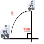
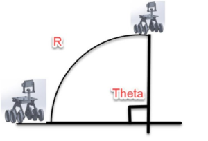
R*θ is a way of working out how far a wheel travels on a circular path. An arc with 180° gives you a θ of π radians. For example, an arc with a radius of 40 inches, the total distance the pathfinder will travel on that arc is π * 40, or roughly 125 inches. But if the center of the pathfinder is on the arc, then each wheel will travel a different arc – one outside, one inside. The wheels on the pathfinder are about 18 inches apart, so each wheel is 9 inches from the center. One wheel is on an arc of 31 inches’ radius and the other is on an arc of 49 inches (40 +/- 9). The inside wheel will travel about 97 inches and the outside wheel will travel 153 inches. The ratio between the two distance will be 150:100 (rounding), or 1: 0.67, will always give you that arc. Regardless of speed if one wheel moves 1 inch at the same time the other moves 0.67 inches. Using this ratio, the arc will be given at any speed or voltage applied to the wheels.

picture2