Solar Cell Current Sensing

By Edgardo Villalobos

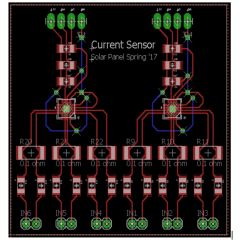
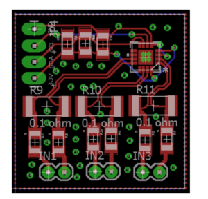
Custom PCB created by combining two INA3221 into one board.


Table of Contents

INA3221


Original Eagle CAD


Custom PCB with 2 INA3221


Three INA219 = One INA3221


Description

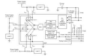
The INA3221 is a three-channel, high-side current and bus voltage monitor. It contains the setup of 3 INA219 single-channel, high-side current and bus voltage monitor.


Setup

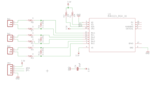
The solar panel on the pathfinder rover contains 6 different panels with 6 solar cells on each panel that are setup in a certain way in series and parallel to get an output of 18 volts and 200 milliAmp from each of the panels to get a total of 18 volts and 1 amps. To test the current flowing through each of the 36 cells, we are going to use the INA3221 current sensor. As described in the INA3221 datasheet, this sensor senses current on buses that can vary from 0V to 26V. Because the INA3221 is three channels, it only measures the current running through 3 inputs, meaning we’ll need 2 per panel. The original Eagle CAD PCB layout was modified in order to get a total of six inputs that will match up perfectly with the 6 cells on each panel, meaning we will only need 6 boards as opposed to 12.

Since the these sensors can only have 4 addresses, I2C multiplexers are required.

Parameters


References

http://www.ti.com/product/INA3221/description

http://www.ti.com/lit/ds/symlink/ina3221.pdf

http://www.ti.com/lit/ds/symlink/ina219.pdf

http://www.switchdoc.com/wp-content/uploads/2015/04/INA3221BOB-042015-V1.0.pdf


Eagle CAD Files

https://drive.google.com/drive/folders/0B4jU8uMDmOoiU1dOM0tzSU1qeHM

  • Custom Eagle CAD Schematic: Current_Sensors.sch
  • Custom Eagle CAD PCB : Current_Sensors.brd
  • Original Eagle CAD Schematic : ina.sch
  • Original Eagle CAD PCB : ina.brd
  • INA3221 Eagle CAD Library : ina.lbr


Pathfinder Fall 2016 Final Summary

Table of Contents

Project Overview

By Sabina Subedi, Project Manager

Project Objective

The Pathfinder is an autonomous rover that is self-sufficient using solar panels. The design of the Pathfinder is inspired by the twin Mars rovers “Spirit and Opportunity.” The Pathfinder will utilize navigation waypoints on Arxterra control panel to traverse through the defined course, articulating ultrasonic range finders and LiDar sensor for obstacle avoidance. Digital slip differential will be implemented for unmanned turning of the rover during it’s course. In order to save battery, the Pathfinder will integrate sensors that will send signals to the motors to stop the wheels from spinning under no load conditions.

Mission Profile

The Pathfinder must successfully navigate a 0.18 mile (roundtrip) course to and from the solar panel charging station defined by the solar panel subproject group. The mapped out course contains 2 staircases with 3 steps each, then concrete path leading to solar panels charging station. The Pathfinder shall travel up and down the steps. The Pathfinder shall avoid any obstacles along the way, using ultrasonic and LiDAR sensors. Pathfinder shall complete its mission in one evening.  The pathfinder shall conduct its mission at night for better operation of the LiDar sensor.

The Design

one

Project Features:

  • Rocker Bogie suspension system
    • High clearance chassis
    • Superior stability on uneven surfaces
    • Obstacle climbing capability
  • Pan and tilt system
    • 2 servos for the rotation of the system, one for pan & one for tilt
    • Provides live video feed utilizing a cellular phone camera
    • Enclosed to protect the phone from external environment
  • GPS Navigation Mode with obstacle avoidance

System Design: 

By Jose Alcantar, Electronics and Controls Engineer
uno

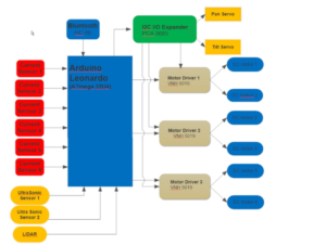
The system block diagram above generalizes how the sensors and actuators will interface through the Arduino Leonardo. First, the Bluetooth receives and transmits any data and the Arduino decodes the data and takes action. The Arduino will either receive sensor data or drive the motors, depending on the commands sent. The diagram also shows the I/O expander is used to control the motor drivers and servos.

Experimental Results:

By Jose Alcantar, Electronics and Controls Engineer

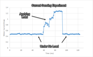
No load conditions threshold:
picture3

The plot above shows the current draw data from one motor driven by the VNH5019. The purpose of this experiment was to find a threshold for finding the current drawn at no load conditions. From the graph, the no load current draw is about 500 mA and when a load is applied the motor draws about 1.3A. The threshold is necessary to set the threshold and shut off the motors when the current draw falls below this threshold.  

Field of View test for Ultrasonic Sensor:
picture1

Purpose:

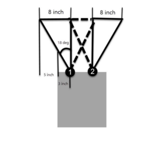
Testing the field of view on the HC-SR04 to find a suitable mounting position for the two ultrasonic sensors along the front of the rover.

Procedure:

An object was placed in front of the ultrasonic sensor about 25 inches away; the position of the object was marked and moved in increments of 5 inches until the object was out of view. When the object was no longer detected the position was marked. The angle of the field of view was then calculated.

Results:

Based on the experiment, the angle of the field of view was found to be 18 degrees when measuring an object 25 inches away. The position of the sensors was determined by considering the clearance needed on each side of the rover. When considering the solar panels, the two ultrasonic sensors need to detect obstacles at least 5 inches to each side of the chassis. This will allow the pathfinder to avoid obstacles that may bump into the solar panels.

Subsystem Design:

By Jose Alcantar, Electronics and Controls Engineer

Interface Definition:
quatro

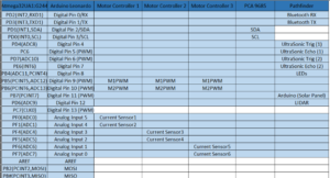
The above table shows the main pinout from the Arduino Leonardo. The main interfacing boards are the three VNH5019 motor drivers the PCA9685 I/O expander, the Bluetooth module, the LEDS, Ultrasonic sensors and the LIDAR.

cinco

The above table shows the interconnections of the PCA96805 I/O expander. The majority of the pins control the direction pins of the 6 H-Bridges and the pan and tilt servos.

Software Design:

By Jose Alcantar, Electronics and Controls Engineer
seis

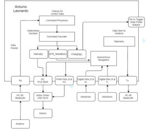
The above flowchart demonstrates how the Arduino receives the incoming data from the Arxterra App and acts based on the commands sent. When a command is sent the command, decoder determines which function to begin. Depending on the mode the Pathfinder will go into either Manual mode, GPS navigation mode or charging state. The called function will drive the motors and read sensor values to complete the requested action.
siete

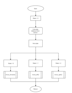
The flow chart demonstrates how the pathfinder will act when avoiding obstacles. The pathfinder will read sensor values and go into either state 1, 2 or 3 depending on the reading of the sensor values. The rover will then either avoid left, avoid right or move forward.

Waypoint Navigation Mode:
ocho

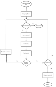
For waypoint navigation mode, the Arduino reads the waypoint coordinates and current coordinates of the pathfinder. Then the distance and heading to the next waypoint is calculated the rover then begins moving to its destination while actively avoiding obstacles and continously updating coordinate data. Once the waypoint is reached the waypoint data is deleted and manual mode is activated.

For more detail on the Waypoint navigatioin algotithm see:

http://arxterra.com/waypoint-navigation/

Manual Mode Flowchart:
nueve

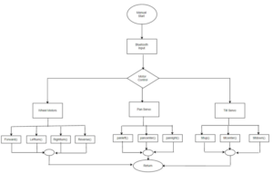
The flowchart shows the basic algorithm to drive the motors when the direction pad is used to control the pathfinder and pan and tilt servos.

For a more detailed explanation of the MOVE functions see:

http://arxterra.com/implementing-move-command-firmware/

Cable Tree

By Nick Lukin, Design and Manufacturing

The cable tree shows approximately where the wires outside of the main PCB will be laid out on the Pathfinder. It includes connectors for items that can be taken on and off the chassis.

cabletree2cabletree3 cabletree

Hardware Design

By Nicholas Lukin, Design and Manufacturing Engineer

Introduction

The overall mechanical design consisted of various key features that ensured the customers design requirements were met. The first feature is the pan and tilt phone system. The customer required that the Pathfinder come equipped with an electronically controlled pan and tilt phone holding mechanism. The next feature is the rocker bogie suspension system. This suspension system helped fulfill the requirement of going over rough desert terrain and makes it possible to climb up and down obstacles such as stairs and rocks. The next feature is that the Pathfinder is made out of material that can withstand desert conditions as per the requirement stated by the customer. The final feature is the seamless interfacing areas on the chassis that makes it possible to properly interface with the solar panels that will be attached to the top of the chassis.

one

Form Factor


Rocker Bogie Suspension System
 two

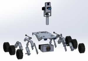
Figure 1: Exploded View

 Figure 1 shows the exploded view of the entire chassis including the rocker bogie suspension system. The system itself allows the pathfinder to go over uneven surfaces while maintaining stability and traction. There are two pivot points located in the suspension system. The middle pivot point is attached directly to the top plate of the chassis and allows the plate to stay level while traversing up and down obstacles such as stairs. The back pivot point allows for a further range of motion when going over various obstacles. Having two independent suspension sides allows the Pathfinder to go over a variety of terrain. Each side reacts independently to obstacles which allows the center of mass to stay relativity stable and low.


Tube Leg Design and Material

  three

Figure 2: Tube Leg Design

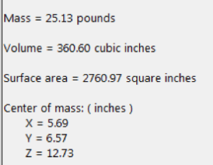
In order to make the Pathfinder look as close as possible to the Spirit/Opportunity rovers it was decided to make the legs of the rocker bogie suspension system out of tubing instead of plate like the previous Pathfinder designs. Not only did this make the Pathfinder look more realistic but it also added more strength to the overall design. It was decided that the material used for the design would be 6061-T6 aluminum because of its high corrosion resistance and overall strength. Figure 2 shows the overall mass properties of the Pathfinder.
four

Figure 3: Mass Properties

The overall weight of the Pathfinder is about 25 pounds as shown in figure 2. This weight it light enough to ensure that the motors do not get overworked. If non aerospace grade aluminum was used such as plain 6061 the weight would be around 32 pounds which is a 20% increase.

Fabrication of Overall Chassis
 five

Figure 3: 2-D Drawing for Fabrication


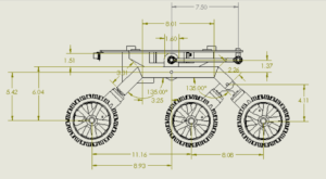
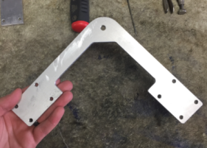
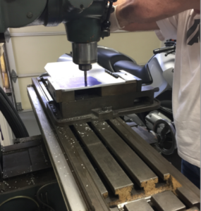
The first step in the fabrication process was to obtain the proper 2-D drawing in order to figure out what material needed to be machined and what needed to be welded. It was decided that the back legs, the top plate and the top side plate would all need to be cut and machined. Figure 4 below shows the machining process.
six seven

Figure 4: Machining Legs and Top Plate


eight

Figure 5: Fabricating Legs


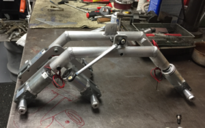
Proper measuring tools had to be used in order to make sure the legs were the correct size and that the overall chassis would be straight when it was planted on all six wheels. Tubing needed to be cut at the proper angles (135 degrees) and welded. Special attention needed to be given while welding to ensure the metal did not warp and create an unwanted dimension.
nine

Figure 6: Final Leg Fabrication

Figure 6 shows the final leg fabrication. Each leg was nearly identical to one another. This helped achieve the goal of keeping symmetry throughout the entire design and made sure the Pathfinder would achieve the proper form factor as required by the customer.
ten

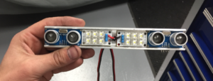
Figure 7: Light/Sensor Bar

 It was a requirement that the Pathfinder was equipped with some type of lighting and ultrasonic sensors. In order to properly attach the lights and sensors to the chassis it was necessary to custom fabricate some type of holding mechanism. A light/sensor bar was machined in order to properly attach the critical lights and sensors. Figure 7 shows the final product.
eleven

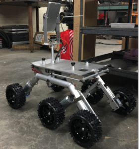
Figure 8: Final Chassis Design

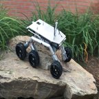
 Figure 8 shows the final chassis completed with the pan and tilt phone system, wheels and electrical all attached. The final design looks nearly identical to the solid works model. Careful preparation and precise fabrication achieved a design that is accurate and that meets the customers’ expectations. 

Pan and Tilt Phone System
 

twelve 

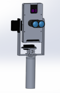
Figure 9: Pan and Tilt Phone Holder


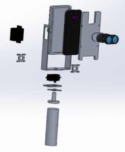
In order for the Pathfinder to see where it is going and to properly connect to the Arxterra control panel the customer required that a Pan and Tilt phone system be built. The system would need to house a Samsung Galaxy S7 edge and be able to withstand a desert environment. The design of the system can be seen in figure 9. The system is controlled through the Arxterra control panel via two servos. We decided to make the phone holder out of 6061-T6 material just like the chassis. This would ensure that the phone would be properly protected and that it was light enough so the servos could move it.
thirteen

Figure 10: Pan and Tilt Exploded

It was also necessary to attach a lidar sensor to the front of the phone case. Lidar was needed in order to properly implement an autonomous driving mode system. The front plate of the phone holder was designed to leave room for the cameras of the phone, to house the lidar sensor and to properly expose the communication antennas of the phone. All these features can be seen in figure 10.
 

fourteen

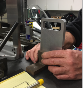
Figure 11: Fabricating Phone Holder

Figure 11 shows the fabrication of the camera view holes of the front case of the phone holder. It was necessary to properly measure the distance between the top of the phone to the end of the camera to make sure that there was no interference between the metal and the camera.
 

fifteen

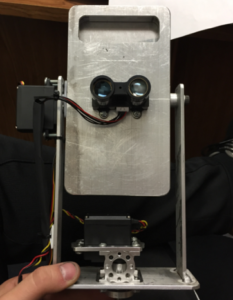
Figure 12: Final Product

Figure 12 shows the final build of the pan and tilt phone holder mechanism. It was necessary to utilize an off the shelf gimbal system to mechanically drive the pan motion of the holder. This part was connected to the pan servo and ensured smooth lateral operation of the entire system.

Interfacing the Solar Panels
 sixteen

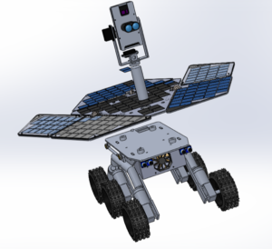
Figure 13: Solar Panels Interfacing

It was necessary that the chassis and solar panels seamlessly interface as per the requirement of the customer. Proper interfacing was achieved by creating mounting stand offs on the top plate of the chassis of the Pathfinder. The solar panels would then have holes that would properly align with the mounting pads and a small thumb screw would be used in order to properly secure the connection. These stand offs can be seen on the top plate of the chassis in Figure 13. The pan and tilt phone holder would also need to come off by hand in order to properly interface. This was achieved by machining a threaded stud to the top of the phone holder stand. The customer could then easily screw the phone holder on and off by hand.


Figure 14: Actual Interfacing

Figure 14 shows the actual interfacing of the solar panels and the chassis assembly. The 4 thumb screws that were utilized can be seen in figure 14. It was also noticeable that the proper form factor was achieved between the solar panels and the chassis.


PCB Layout
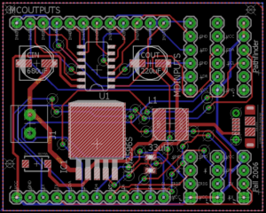
eighteen

Figure 15: Final PCB Design

A custom PCB design was required in order to interface all of the boards that were utilized to control the Pathfinder. The overall function of the board was to take various pins from the Arduino and rout those pins to other boards that could directly connect to the custom PCB. Two ultrasonic sensors, a Bluetooth module, a servo driver board, a LED interface, a LIDAR connection and 3 motor driver boards would all be able to directly connect to the board. The board would also implement a buck converter in order to step down the main battery supply voltage from 12V down to 6V to properly charge the phone in the phone holder system.

Interface Design

In order to properly route all the wires from the Arduino pins to the proper locations it was necessary to lay the board out in an efficient manner. All the pins that required headers were laid out as close to the edge of the board as possible. They were also spaced apart so that room was left for whatever connectors would be used. 45 degree bends were utilized on all traces in order to maintain a clean and professional looking PCB. A ground plane was utilized for all ground connections and a power bus was used in order to properly connect VCC across all pin connections. A power plane could not be used since the buck converter would also be on the same board and would be utilizing a different voltage level at its input.

Buck Converter

 nineteen

Figure 16: Typical Buck Design

 The LM2596 chip was selected for the buck converter. This chip allows a maximum of 3 amps to be passed through it and has an input voltage range of up to 40 volts and can step down voltages as low as 3.3 volts. For the phone charger we designed the buck converter to output 6 volts to properly charge the Samsung Galaxy S7 edge. All surface mount components were utilized for the design and attention to detail was key during the lay out process. Per the data sheet it was necessary to place the inductor and capacitors as close to the chip as possible. It was also necessary to use the correct size power traces to prevent overheating and possible damage to the board. The buck converter was designed to output a max of 1 amps and therefore a maximum power trace of .032 inches was used. This thick trace can be seen on figure 15 at the input of the buck converter. A micro usb was used on the output of the buck so the phone could easily plug into the charger.


Soldering Process


Figure 17: Soldering the Board 

The custom PCB was soldered by hand and then was tested for proper functionality. It was noticed that there was a direct short between ground and Vcc. Initially it was thought that the soldering process caused the short but upon further inspection it was determined that the board came shorted from the factory. Two other boards that were not yet soldered were tested and they both had direct shorts between Vcc and ground.

Verification and Validation Test

https://drive.google.com/open?id=0Bzq09K9mZabrd0E4a01mUElLdlE

Work Breakdown Structure (WBS)

wbs

Resource Reports

Please refer to the Project Resources section to find the resource reports, including Mass, Cost and Power Report.

Top Level Schedule

schedule

The general top level schedule was created using the generic rubric provided on the class website. The top level schedule specific to the Pathfinder (Chassis subproject) was created using the Work Breakdown Structure above and the general top level schedule. This schedule consists of all tasks that are to be completed before the end of the semester, December 15th, 2016. The project milestones are broken down into four phases: Planning, Design, Assembly and Project Launch. The tasks within the different phases are then divided up by the divisions. All division members are assigned specific tasks that they are responsible for, per “Job Descriptions” document available on the class website. Main tasks then were broken down into sub-tasks, if applicable. All tasks include start and finish dates, as well as percent complete. 

Conclusion and Future Plans

Overall the project was a success as we were able to build a functioning rover that achieved the majority of the requirements that were established by the customer. The mechanical design worked as expected with only some small issues. One improvement that is necessary is adding stops to the back pivot point of the rocker bogie suspension system. The range of motion needs to be limited at some point in order to properly go up obstacles such as stairs. Another improvement would be to possibly get bigger wheels. The larger the wheels the better it can go up and over obstacles. I believe that the current design is sufficient for future students to build off of and improve upon.

Project Resources


Waypoint Navigation

Waypoint Navigation for the Pathfinder

By Jose Alcantar, Electronics and Controls Engineer

Introduction:

This blog post covers the proposed waypoint navigation algorithm along with some issues regarding how the GPS data was transmitted and decoded by the Arduino. Sample code and navigational calculations are included.

Navigation Algorithm:

When the pathfinder travel mode is to Autopilot, the Arxterra App begins transmitting heading information, current coordinate information of the smartphone and waypoint coordinates, if any. The basic control logic is as follows:

  1. If Autopilot mode is engaged, begin Waypoint Navigation
  2. Process any new GPS information and update the course and distance to the target waypoint.
  3. Read heading information to get current bearing and decide the desired direction to turn the pathfinder.
  4. Begin moving the pathfinder and check for any obstacles to avoid.
  5. If waypoint is reached, switch to manual control.

The code to handle each of these was written in separate functions.

Autopilot Mode:

When the autopilot mode is engaged the WAYPOINT_ON command is called, which begins the Navigation algorithm. The first function called retrieves the heading information from the smartphone which is sent as a data packet containing the command id and the heading information in hex values. For more detail regarding formatting the data see link below,

http://arxterra.com/heading-and-gps-coordinates-formatting/

After the heading is retrieved, a function is called to calculate the difference between the current heading and the heading to the desired waypoint.

The following code demonstrates how to calculate the turn:


// returns distance in meters between two positions, both specified

// as signed decimal-degrees latitude and longitude. Uses great-circle

// distance computation for hypothetical sphere of radius 6372795 meters.

// Because Earth is no exact sphere, rounding errors may be up to 0.5


void calcDesiredTurn(void)

{

//calculate where we need to turn to head to destination

headingError = targetHeading – currentHeading;


//adjust for compass wrap

if (headingError < -180)

headingError += 360;

if (headingError > 180)

headingError -= 360;

// calculate which way to turn to intercept the targetHeading

if (abs(headingError) <= HEADING_TOLERANCE) // if within tolerance dont turn

turnDirection = straight; // GO FORWARD

else if (headingError < 0)

turnDirection = left;     // TURN LEFT

else if (headingError > 0)

turnDirection = right;    // TURN RIGHT

else

turnDirection = straight; // GO FORWARD

} // calcDesiredTurn()


After the target heading is calculated, the distance to the target waypoint is calculated using the following code:

int distanceToWaypoint()

{


float delta = radians(currentLon – waypointLon);

float sdlong = sin(delta);

float cdlong = cos(delta);

float lat1 = radians(currentLat);

float lat2 = radians(waypointLat);

float slat1 = sin(lat1);

float clat1 = cos(lat1);

float slat2 = sin(lat2);

float clat2 = cos(lat2);

delta = (clat1 * slat2) – (slat1 * clat2 * cdlong);

delta = sq(delta);

delta += sq(clat2 * sdlong);

delta = sqrt(delta);

float denom = (slat1 * slat2) + (clat1 * clat2 * cdlong);

delta = atan2(delta, denom);

distanceToTarget =  delta * 6372795;

//————-Edit to turn off navigation———-//

// check to see if we have reached the current waypoint

if (distanceToTarget <= WAYPOINT_DIST_TOLERANCE)

waypoint_on = 0;

//—————————————————//

return distanceToTarget;

}  // distanceToWaypoint()


The previous functions return the new heading in degrees and the distance in meters

the next function, checkSonar() is called to read the ultrasonic sensor distance values.


void checkSonar(void)

{

distR = 0; distL = 0;

digitalWrite(11,LOW);

delayMicroseconds(2);

digitalWrite(11,HIGH);

delayMicroseconds(10);

digitalWrite(11, LOW);


pulse_width = pulseIn(8, HIGH);


distR = (pulse_width/2)/29.1;

delay(60);


digitalWrite(10,LOW);

delayMicroseconds(2);

digitalWrite(10,HIGH);

delayMicroseconds(10);

digitalWrite(10, LOW);


pulse_width = pulseIn(4, HIGH);

distL = (pulse_width/2)/29.1;


delay(60);


if( distR > MAX_DISTANCE_IN && distL > MAX_DISTANCE_IN)

{

distR = MAX_DISTANCE_IN;

distL = MAX_DISTANCE_IN;

}


}  //checkSonar()

After calculating the distance, target heading and reading the sensor values the moveAndAvoid() function is called to move the pathfinder to its destination while avoiding obstacles.

void moveAndAvoid(void)

{

if(distL >= SAFE_DISTANCE && distR >= SAFE_DISTANCE)    //no close objects in front

{

if(turnDirection == straight)

{

speedLeft = FAST_SPEED;         //PWM SIGNAL FOR BOTH MOTORS

speedRight = FAST_SPEED;

left_forward();

right_forward();

}

else if(turnDirection == left)

{

speedLeft = TURN_SPEED * .85;         //PWM RATIO FOR BOTH MOTORS

speedRight = TURN_SPEED;

left_forward();

right_forward();

}

else if(turnDirection == right)

{

speedLeft = TURN_SPEED;

speedRight = TURN_SPEED * .85;

left_forward();

right_forward();

//driveMotor->setSpeed(speed);

//driveMotor->run(FORWARD);    // turn direction

//turnMotor->run(turnDirection);

//else(turnDirection == right)

//speed = TURN_SPEED;

}

return;

}

if ((distL > TURN_DISTANCE || distR > TURN_DISTANCE)  && (distL < SAFE_DISTANCE || distR < SAFE_DISTANCE)) //not yet time to turn, but slow down

{

if(turnDirection == straight)

{

speedLeft = NORMAL_SPEED;   // PWM FOR MOTORS

speedRight = NORMAL_SPEED;

left_forward();

right_forward();

}

else if(turnDirection == left)

{

speedLeft = TURN_SPEED * .85;     //SPEED RATIO FOR MOTORS

speedRight = TURN_SPEED;

left_forward();

right_forward();

// already turning to navigate —-> Direction to turn

}

else if(turnDirection == right)

{

speedLeft = TURN_SPEED;

speedRight = TURN_SPEED * .85;

left_forward();

right_forward();

}

return;

}

if ((distL < TURN_DISTANCE || distR < TURN_DISTANCE) && (distL > STOP_DISTANCE || distR > STOP_DISTANCE)) // getting close, time to turn to avoid object

{

speedLeft = SLOW_SPEED;     //PWM FOR MOTORS

speedRight = SLOW_SPEED;

left_forward();

right_forward();

switch(turnDirection) // decides whether to turn left or right

{

case straight:        // going straight

{

if (headingError <= 0)

turnDirection = left;

else

turnDirection = right;

speedLeft = SLOW_SPEED;

speedRight = SLOW_SPEED * .85;

left_forward();

right_forward();

//turnMotor->run(turnDirection);  // turn in the new direction

break;

}

case left:                        // if already turning left, try right

{

speedLeft = SLOW_SPEED;

speedRight = SLOW_SPEED * .85;

left_forward();

right_forward();

//turnMotor ->run(TURN_RIGHT);

break;

}

case right:

{

speedLeft = SLOW_SPEED * .85;

speedRight = SLOW_SPEED;

left_forward();

right_forward();

//turnMotor ->run(TURN_LEFT);

break;

}

} //end SWITCH


return;

}


if (distL <  STOP_DISTANCE || distR < STOP_DISTANCE)          // too close, stop and back up

{

left_release();

right_release();

//driveMotor->run(RELEASE);            // stop

//turnMotor->run(RELEASE);             // straighten up


turnDirection = straight;

speedLeft = NORMAL_SPEED;

speedRight = NORMAL_SPEED;

left_reverse();

right_reverse();

//driveMotor->setSpeed(NORMAL_SPEED);  // go back at higher speet

//driveMotor->run(BACKWARD);

while (distL < TURN_DISTANCE || distR < TURN_DISTANCE)       // backup until we get safe clearance

{

currentHeading = readCompass();    // get our current heading

calcDesiredTurn();                // calculate how we would optimatally turn, without regard to obstacles

checkSonar();

delay(100);

} // while (sonarDistance < TURN_DISTANCE)

left_release();

right_release();

//driveMotor->run(RELEASE);        // stop backing up

return;

} // end of IF TOO CLOSE


} //moveAndAvoid


NOTES: One of the main issues with the waypoint navigation is that the heading data received does not give the full 0 – 360 degree range. When formatting the data, the heading is given from 0 to 180 degrees (North = 0 and South = 180) going counter clockwise, but any heading past 180 degrees does not transmit correctly. When formatting, the values given from the data packet, the degree range from (180 to 360) loops back, (going counter clockwise) the degree range is North = 180 and South = 360 degrees this causes an issue with calculating the correct heading values. It is recommended that Jeff is contacted to resolve this issue.


Conclusion:

With the following algorithm the pathfinder should be able to reach its destination with no issues.

Stress Test

Stress Test

By: Nick Lukin (Design and Manufacturing Engineer) 

Introduction

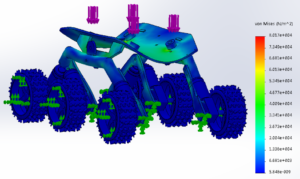
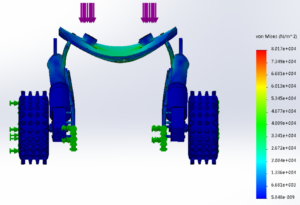
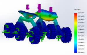
In order to ensure that the Pathfinder chassis could support the weight of the solar panels in order to properly interface it was necessary to perform a stress/displacement test in Solidworks. The solar panels overall weight was a maximum of 50lbs. The chassis was designed so the panels could sit on top of aluminum standoffs welded to the top plate of the chassis. The force in Newtons was calculated and applied to the standoffs.


one

Figure 1: Stress Test Results

two

Figure 2: Stress Test Results Continued


Analysis

In order to figure out the appropriate force to apply to the model it was necessary to convert the maximum weight of the solar panels into Newtons (1 Newton = 0.2248 lbs). Therefore 50 lbs converts into about 222 Newtons. This number was used for the simulation in order to see how much the maximum weight of the solar panels would affect the chassis. Figures 1 and 2 show the results of the stress test performed in Solidworks. The test results show an exaggerated view of exactly how and where the chassis would begin to deform. It is noticed that the chassis max deformation is about 8.017e+004 von Mises which is very little. The overall characteristics and shape of the deformation is as expected.

three

Figure 3: Displacement Results

four

Figure 4: Displacement Results


Figures 3 and 4 show the displacement of the chassis and further show how the chassis will be affected by the maximum weight of the solar panels. The displacement results give a millimeter value of exactly how much the metal will move. It is noticed that the top plate bends a maximum of 1.226e-003 mm which is very small (less than a millimeter). This number is acceptable and confirms that the design of the chassis can withstand the maximum weight of the solar panels.

Conclusion

After running the appropriate stress tests in Solidworks it was determined that the design shown in the figures above was strong enough to support the weight of the solar panels. Being that the chassis is the base of the entire pathfinder it must support the weight of everything that is attached to it. The stress tests performed show the strength of the chassis and confirm that the requirement of properly interfacing between the chassis and solar panels is achieved.

Form Factor

From Factor

By: Nick Lukin (Design and Manufacturing Engineer)

picture1n


Introduction

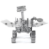
In order to meet the requirement of the Pathfinder being dimensionally proportional to the actual Spirit and Opportunity rovers it was necessary to develop a measurement method in order to properly scale the overall design.

picture2n

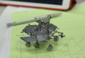
Figure 1: Small Scale Model

Analysis

A small scale model of the actual spirit/opportunity rover was used in order to get base dimensions to work with and to develop an appropriate scale factor. Figure 1 shows the small model that was used to take measurements from. 10 different measurements were taken from the small model. The measurements are summarized in Figure 2.

picture3n

Figure 2: Summary of Measurements/Dimensions

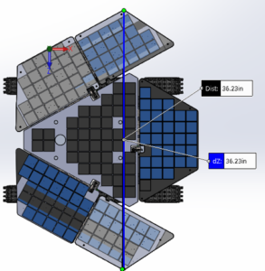
The solar panels group was limited to how wide they could make their overall panels because they needed to be able to fit inside the cabinet in ECS 316. The cabinet is 19 inches wide which meant the max width of the center solar panel was to be 19 inches. Therefore the scale factor of the overall design relied on how wide the solar group decided to make their panels. The final overall width and length of the solar panels was 25.39” and 36.26” respectively. The center panel width was 18.45” which was within the cabinet measurement of 19”. Once the solar panel group finalized their measurements the proper scale factor could be calculated. Dividing the overall solar panel width and length by the small model width and length gave a scale factor of 10.097.

npicture5

Figure 3: Overall Height

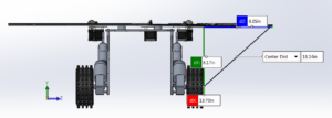
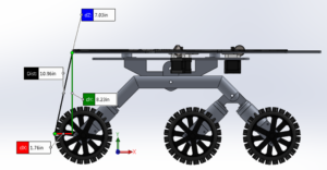
In order to find the overall height of the solidworks model the overall height of the small model (29.6mm) needed to be multiplied by 10.097. The result is about 298.88mm or 11.77 inches as shown in figure 3.

npicture1

Figure 4: Overall Width (wheel to wheel)

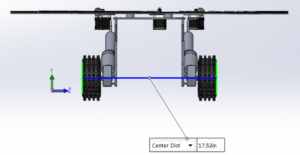
The overall width wheel to wheel on the small model was 44mm. Multiplying this number by the scale factor yielded a measurement of about 444.29mm or 17.49 inches as shown in figure 4.

npicture2

Figure 5: Length (wheel middle to front)

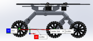
The length between the center of the front wheel and the middle wheel on the small model was 30.2mm. Multiplying this number by the scale factor yielded a measurement of about 304.9mm or 12.01 inches as shown in figure 5.

npicture3

Figure 6: Length (wheel middle to back)

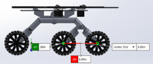
The length between the center of the middle wheel to the center of the rear wheel on the small model was 20.4mm. Multiplying this number by the scale factor yielded a value of 205.99mm or 8.11 inches as shown in figure 6.

picture1n

Figure 7: Side Solar

The measurement between the end of the side solar panel and the edge of the wheel on the small model was 22.8mm. This number was multiplied by the scale factor to get a number of about 230.22mm or 9.05 inches as shown in figure 7.

npicture11

Figure 8: Front Solar Measurement

The measurement between the front of the solar panel edge and the front edge of the wheel was 4.4mm on the small model. After multiplying by the scale factor the measurement came out to 44.43mm or 1.75 inches as shown in figure 8.

npicture

Figure 9: Back Solar Measurement

The measurement between the back solar panel edge and the edge of the back wheel on the small model was 3.5mm. Mulitplying by the scale factor yielded a measurement of 35.34mm or 1.39 inches as shown in figure 9.


npicture9 npicture10

Figure 10: Length/Width Solar Panels

The overall length and width of the small model solar panels was 92.5 and 63 mm respectively. Multiplying by the scale factor yielded measurements of 36.26 and 25.39 inches respectively as shown in figure 10.


npicture11

Figure 11: Phone Holder Height

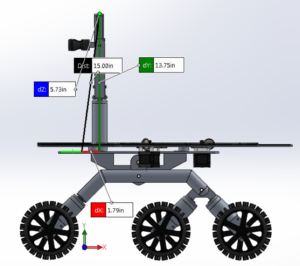
The measurement of the phone holder from the top plate of the chassis to the very top of the phone on the small scale model was 34.4mm. Multiplying by the scale factor yielded a value of 347.35mm or 13.68 inches as shown in figure 11.

Conclusion

Overall we were successful in creating a model in solidworks that matched the proper form factor of the spirit/opportunity rovers. In order to properly achieve the correct proportions it was necessary to assume that the small scale model that was used was accurately proportional to the actual spirit/opportunity rovers. If this is the case our model meets the requirement of achieving the proper form factor. A plus or minus 0.25 tolerance was put on the actual building of the model to account for any errors during the fabrication process.

Experiment: LiDAR Lite

By Jose Alcantar, Electronics and Controls Engineer

Introduction

The LIDAR is a laser range finder which can measure distances of up to 40 meters with an accuracy of ­­±2.5 cm. The device can be used via I2C interface or through pulse width modulation. The LIDAR is to be implemented onto the pathfinder for the use of obstacle detection and avoidance requirement.

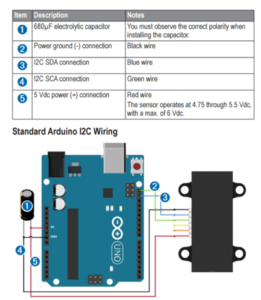
Wiring Diagram:


picture6

For testing purposes the LIDAR was wired as shown by the wiring diagram. An Arduino Uno was used using the SCL and SDA I2C pins.

Purpose:

The purpose of this experiment is to calculate and test the field of view of the LIDAR sensor and to test sunlight interference.

Procedure:

An object was placed 0.5 meters away and directly in front of the sensor. The center point of the object was marked and moved in increments of about 0.5 cm to the left until the sensor no longer detected the object. This point was marked and the object was once again replaced to the center and moved in increments of 0.5 cm to the right of the sensor. When the sensor no longer detected the object, the position was marked. The beam diameter was calculated based on the distance between the two points. Using the same method, the experiment was repeated at 1 meter then 1.5 meters.

The LIDAR was tested outside in sunlit conditions to observe the interference of sunlight on the sensor. The sensor was pointed at various objects and the data was observed for any interference.

Results:

The beam diameter was calculated for each of the test runs. At 0.5 meters, the diameter of the beam was well within the mm range. At this distance, the diameter of the beam was about 15 mm. At 1 meter, the calculated beam diameter was about 16 mm. At 1.5 meters, the diameter of the beam was about 2 cm.

Using the LIDAR outside showed no obvious interference. Although, pointing the sensor at different objects with various reflectivity did have some effect on the data. The sensor did have less accurate results on objects with more reflective surfaces.

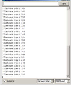
The following table is an example of the output from the serial port on Arduino IDE.

picture7

Heading and GPS Coordinates Formatting

By Jose Alcantar, E&C Engineer

picture4Introduction:

The GPS information received through the Arxterra control panel can be sent through three different data types. The first data type is a 32-bit floating point, the second is a 64-bit floating point or “double” and lastly a 32-bit integer or “long”. Depending on how the settings are configured through the “Robot Capabilities Configuration” menu in the app, the user can choose between any of these three data types. For further information on the data types see the blogpost by Jeff Gomes,

https://www.arxterra.com/arxterra-now-supports-waypoint-navigation/

For our purpose, the 32-bit integer was selected as the data type due to some formatting issues when using the 32-bit floating or 64-bit floating types.

To begin with formatting the coordinates, it must first be understood what values are being sent through the Arxterra app. From the link above, Gomes explains that for the 32-bit integer the units are set to decimicrodegrees. This means that for example, coordinates 33.794904, -117.913712 would be encoded as 33794904, -117913712. The app sends the coordinate values through a 16-byte packet, in which the first 4 bytes are the latitude and the last 4 bytes are the longitude coordinates, bytes being represented in hexadecimal.

picture3

There are different commands available related to GPS navigation, further described in this link,

https://www.arxterra.com/pathfinder-arxterra-communication-commands/

Example:

The following firmware code is based on the WAYPOINT _COORD command, which is used to receive the waypoint coordinate packet data and to format the coordinates into usable values.

After a waypoint is created, for example, 33.794904, -117.124567, the app converts these values into decimicrodegrees and sends the values to the MCU as a 32-bit long. The data being sent will be as follows

{A5, 10 (packetlength),14 (command id), 02 03 AB 58 F9 04 D6 80, (checksum)};

picture4

To extract the data through the Arduino some variables must first be declared:

long waypointLat4;

long waypointLat3;

long waypointLat2;

long waypointLat1;

unsigned long waypointLat;


long waypointLon4;

long waypointLon3;

long waypointLon2;

long waypointLon1;

unsigned long waypointLon;


The byte vales are extracted from the packet and the bits are shifted to be stored into a 32-bit unsigned long.

void waypoint_coordHandler (uint8_t cmd, uint8_t param[], uint8_t n)

{

waypointLat4 = param[0];

waypointLat3 = param[1];

waypointLat2 = param[2];

waypointLat1 = param[3];

waypointLat = (waypointLat4 << 24 | waypointLat3 << 16| waypointLat2 << 8| waypointLat1);


waypointLon4 = param[4];

waypointLon3 = param[5];

waypointLon2 = param[6];

waypointLon1 = param[7];

waypointLon = (waypointLon4 << 24 | waypointLon3 << 16| waypointLon2 <<                  8| waypointLon1);

waypointLon = ~waypointLon;

waypointLon = (waypointLon + 1) * -1;

}

The longitude coordinates require a secondary step to get the right value. Because longitude is a negative value, a 2’s complement operation must be done on the final value to get the right coordinate. Using this formatting, successfully converts the packet data being sent into usable coordinates needed for GPS navigation.

Conclusion:

Following this method, the GPS data sent through the Arxterra control panel can be converted into usable values, which will help with autonomous navigation.

Resources:

https://www.arduino.cc/en/Reference/Bitshift

https://www.arduino.cc/en/Reference/UnsignedLong

https://www.arduino.cc/en/Reference/Long

https://en.wikipedia.org/wiki/Two’s_complement


Implementing MOVE Command Firmware

By Jose Alcantar, Electronics and Controls Engineer

Introduction:

The pathfinder is controlled using the direction pad on both the control panel and through RC mode on the Arxterra app. When using the D-pad, the MOVE command is called from the 3Dotlibrary which is used to control the movement of the motors. Through the design of the 3Dotlibrary, pins 5,6,10 and 13 on the Arduino Leonardo are tied to the MOVE command. Because of how are system is designed, firmware was written to take advantage of the data from the D-pad and MOVE command, without using the dedicated pins.

When a button is pressed on the D-pad a packet is sent through Bluetooth and is decoded by the Arduino. The packet data is sent in the following format:

{A5,  (packetlength), 01 (command id), 01 80 01 80, (checksum)};

The first value after the command id specifies the direction for the left set of wheels on the pathfinder followed by the second byte which is the PWM value to control the speed of those motors. The last next two bytes are used to control the right set of motors.

The following is a brief description of how the index values are interpreted


/***********************************

* motion command = 0x01

* motordata[3]   left run    (FORWARD = index 1, BACKWARD = index 2,

BRAKE =   index 3, RELEASE = index 4)

* motordata[4]   left speed  0 – 255

* motordata[5]   right run   (FORWARD, BACKWARD, BRAKE, RELEASE)

* motordata[6]   right speed 0 – 255

* example

* forward half speed  0x01, 0x01, 0x80, 0x01, 0x80 0101800180

***********************************/


Firmware:

Understanding the data being sent from the D-pad, firmware was written for the motor controls. A series of if-else statements were used to account for the different data packets that the Arxterra app transmits:


void moveHandler (uint8_t cmd, uint8_t param[], uint8_t n)

{

Serial.write(cmd);             // move command = 0x01

Serial.write(n);               // number of param = 4

for (int i=0;i<n;i++)          // param = 01 80 01 80

{

Serial.write (param[i]);

}


if(param[0] == 1 && param[2] == 1)

{

input_pwm1 = param[1];

input_pwm2 = param[3];

left_forward();

right_forward();


}

else if( param[0] == 2 && param[2] == 2)

{

input_pwm1 = param[1];

input_pwm2 = param[3];

left_reverse();

right_reverse();

}

else if( param[0] == 1 && param[2] == 2)

{

input_pwm1 = param[1];

input_pwm2 = param[3];

right_turn();

}

else if(param[0] == 2 && param[2] == 1)

{

input_pwm1 = param[1];

input_pwm2 = param[3];

left_turn();

}

else if( param[0] == 1 && param[2] == 4)

{

input_pwm1 = param[1];

input_pwm2 = param[3];

left_forward();

right_release();

}

else if(param[0] == 2 && param[2] == 4)

{

input_pwm1 = param[1];

input_pwm2 = param[3];

left_forward();

right_release();

}

else if(param[0] == 4 && param[2] == 1)

{

input_pwm1 = param[1];

input_pwm2 = param[3];

left_release();

right_forward();

}

else if(param[0] == 4 && param[2] == 2)

{

input_pwm1 = param[1];

input_pwm2 = param[3];

left_release();

right_reverse();

}

else if(param[0] == 4 && param[2] == 4)

{

input_pwm1 = param[1];

input_pwm2 = param[3];

left_release();

right_release();

}


Conclusion:

Following this code format, the motors can be controlled to move forward, reverse, brake, and release. Depending on the values being transmitted, the functions to drive the motors are called. The PWM values are then extracted from the packet and stored onto a variable to control the speed.