Spring 2016 Pathfinder: Project Summary


IMG_3253

By:

Peiyuan Xu (Project Manager)

Approved by Peiyuan Xu (Project Manager)

Approved by Xiong Lee (System Engineer)

Table of Contents

Executive Summary

Project Objectives

The spring 2016 Pathfinder Rover was inspired by NASA’s MARs Exploration Rover-“Sojourner”. The profile for this semester’s project is to imitate the design of “Sojourner” Rover to prototype a new generation of Pathfinder Rover that implements the Rocker Bogie Suspension System as well as being self-sufficient by using solar panels. The Pathfinder is allowed to have the solar panels charging the battery for up to 8 hours during the day time. Then the customer can spend up to 4 hours at night walking and exploring with the Pathfinder. Ultimately, The customer can use Arxterra control panel on the PC to navigate the Rover by using the cursor to click a point on the map. This generation of Pathfinder Rover is also designed to test and implement SLAM (Simultaneous Localization and Mapping) technology for autonomous vehicles.

Mission Profile:
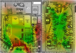
mission WiFi Stength                                                             Figure 1 – CSULB WiFi Strength map

Since our Pathfinder Rover will be tested at the entire CSULB campus. We need to find out where there is the best Wi-Fi signal  in order to gain the stable video stream from the android phone to the Arxterra. The system engineer Xiong Lee was able to use an android App called Wi-Fi Maximiser to map out the  Wi-Fi signal strength around CSULB campus.  Based on the strength of the Wi-Fi signal, our mission will be narrowed down to the area covered with green on the map. We suggest the customer not to go through the area covered with red because there might be some packet loss and signal lag around the area. We also think this Wi-Fi signal strength map can be useful for other EE 400D project in which case they need to explore the CSULB campus as well.

The changes that made to the Mission Profile and Project Objective can be found here:

Spring 2016 Pathfinder: Mission Profile and Project Objective Update

Design

3D illustration

                                                                      Figure 2 – 3D Model                  

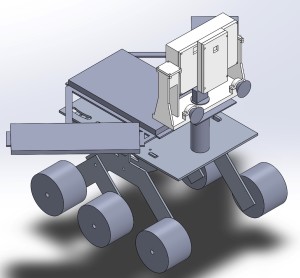
The image above is the 3D illustration in SolidWorks that shows the overall design of the pathfinder.

3D illustratioin2

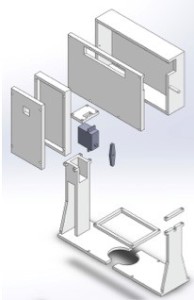
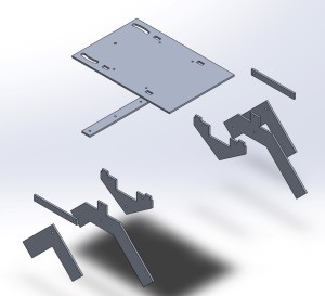
                                                                Figure 3 – Exploded Model                              

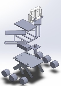
This image above gives the exploded view of the Project design. On the top is the Tilt system with the encasement for Google Tango tablet and Android Phone. Below that are the 3 solar panels with resemble the shape of the Arxterra logo. Then there is a metal box to protect all the electronic components. Following that is our new chassis with Rocker Bogie System.

For more details on the structures of this design, refer to:

Spring 2016 Pathfinder Design and Manufacturing – Rocker Bogie Suspension System Design

Spring 2016 Pathfinder Design and Manufacturing – Tilt System Finalized Design

Project Features:

Rocker Bogie Suspension System

  • Designed for superior vehicle stability on the uneven surface
  • Obstacle-Climbing Capability
  • High-clearance chassis
  • Slow-speed application

62                                                                 Figure 4 – Rocker Bogie System

New Tilt system for Tango tablet and Android Phone

  • Has two servos. One controls Pan system, one controls Tilt system
  • Allow stream video from Android Phone correlates with Point Cloud data in Google Tango tablet
  • Protect the phone and Tango tablet

1615                                                                       Figure 5 – Tilt System

Solar Panels

  • Self-sufficient
  • Use three pieces of solar panels to resemble the Arxterra logo

13421                                                                    Figure 6 – Solar Panels

SLAM  (Project Tango Modules)

Access to the Point Cloud Data (send data out via Tango Bluetooth API)

Use Depth perception and IMU sensors to navigate Pathfinder go where the user wants to go (Developing)

Screenshot_2016-04-07-22-38-12                                                                 Figure 7 – Point Cloud App

System Design

1                                                            Figure 8 – System Block Diagram

The system block diagram above shows how all of the components interface with each other. First, transmission of data from an android phone or the Arxterra control panel via HC-06 Bluetooth module will tell the Arduino Mega what to do. The Arduino Mega will interpret this data and send it out through the motor shield or servo driver to drive the pathfinders movement. The system block diagram also depicts how the charge controller will interface the power supply and the solar panels to the VHN5019 Motor shield that will drive the pathfinder.

For more information about the system design, refer to:

Spring 2016 Pathfinder: System Block Diagram & Interface Matrix

Experimental Results:

Current Drawn By Motors

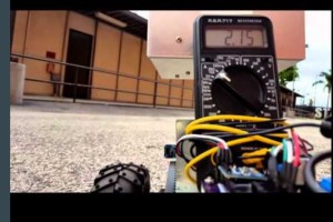
2                                                         Figure 9 – Current Drawn Test

The purpose of this test is to find the current drawn by the motors on different terrains and in different driving modes (Braking abruptly, Rotating (Under High Stress) and Running forward/backward (Normal Driving) . This test is crucial for us to gain the discharging time of the batteries in order to meet the Level 1 requirement of constantly running for 4 hours.

For Project Level 1 requirements, refer to:

http://arxterra.com/spring-2016-pathfinder-preliminary-project-plan/

Results:

Peak current: 4.8 A (Under highest stress)

-Ex. braking abruptly, rotating, etc

Average current: 1.2 A (Normal driving)

Theoretical discharge time:

20 Ah / 4.8 A = 4.16 hours (high stress)

20 Ah/ 1.5 A = 13.33 hours (normal driving)

Actual Discharge time to 50% : 6.5 hours

This test is conducted for the Wild Thumper chassis

Video Demo

For more information about this current drawn test, refer to:

Spring 2016 Pathfinder: Current Drawn Test

Charging Batteries Using Solar Panels
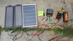
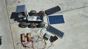
3                                                         Figure 10 – Solar Panels charging the batteries

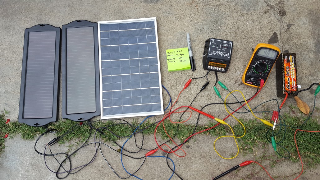
The project objective stated that the pathfinder needs to be self-sufficient by using solar panels. This test is to measure the total current the solar panels can supply at direct sunlight. In reality, the charging capability of solar panels will vary depends on the weather condition, therefore, we include some of the other tests for comparison of the worst case scenario.

Results:

-Direct sunlight: 850 – 950 mA

-Shady area: 500 – 750 mA

-Rain or cloudy: 100 – 300  mA

  •  Important note (current supply  by the solar panel  determine the time required  to  charge the battery )
  • After charging these batteries in direct sunlight for 8 hours, the voltage level of the batteries increased from 4.0 V to 6.5V which is from 54% to 87%.
  • This would meet our Level 1 requirement since it takes around 6 hours of normal conditions run time to deplete our batteries from 7.4 V to 3.4 V.

For more information on how we implement solar panels, refer to:

Spring 2016 Pathfinder Solar Panels Implementation

Project Tango Modules
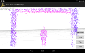
Screenshot_2016-04-07-22-38-12                                                        Figure 11 – Project Tango: Point Cloud

This spring 2016 Pathfinder project used Google’s Project Tango as a platform to test and implement SLAM (Simultaneous Localization and Mapping) technology for autonomous vehicles. Project Tango uses computer vision to give device the ability to know the position in the relative 3D space as well as the distance from the surrounding objects to the device itself.

For more research work of the Project Tango, refer to:

Spring 2016 Pathfinder: Project Tango Preliminary Research

For more details of the project Tango modules our team accomplished or attempted, refer to:

Spring 2016 Pathfinder: Project Tango Bluetooth API

Spring 2016 Pathfinder: Project Tango – Interactive Visualization of data from Tango using Paraview

Spring 2016 Pathfinder: Project Tango Module#5 – Android to Arduino Via Bluetooth

Subsystem Design

Interface Definition

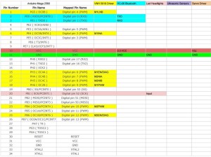
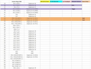
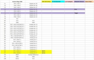
2 3 4                                                           Figure 12 – Interface Matrix

The above interface matrix shows in depth on which pins are used on the Arduino Mega.

For further details on interface matrix, refer to:

Spring 2016 Pathfinder: System Block Diagram & Interface Matrix

One improvement we had after PDR debrief was to highlight the rows and columns with different colors in the interface matrix. Each color represents the corresponding pins used by the component. That makes it a lot easier for us to track the subsystem level pinouts. Also this makes it easy for audience to see during the presentation.

Custom PCB Design

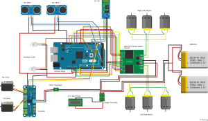
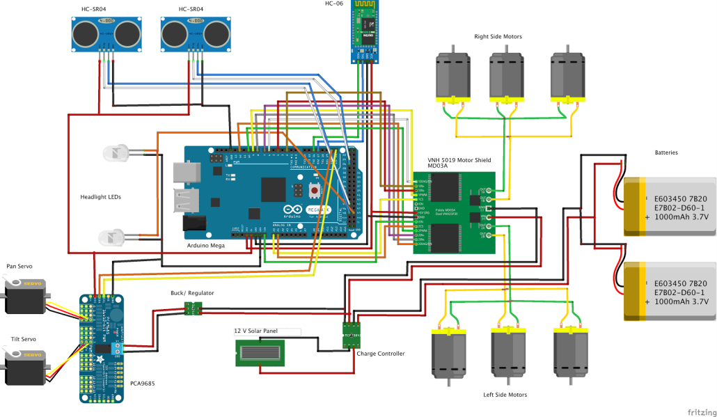
Fritzing Diagram

1                                                           Figure 13 – Fritzing Diagram

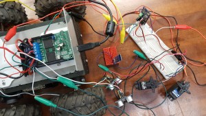
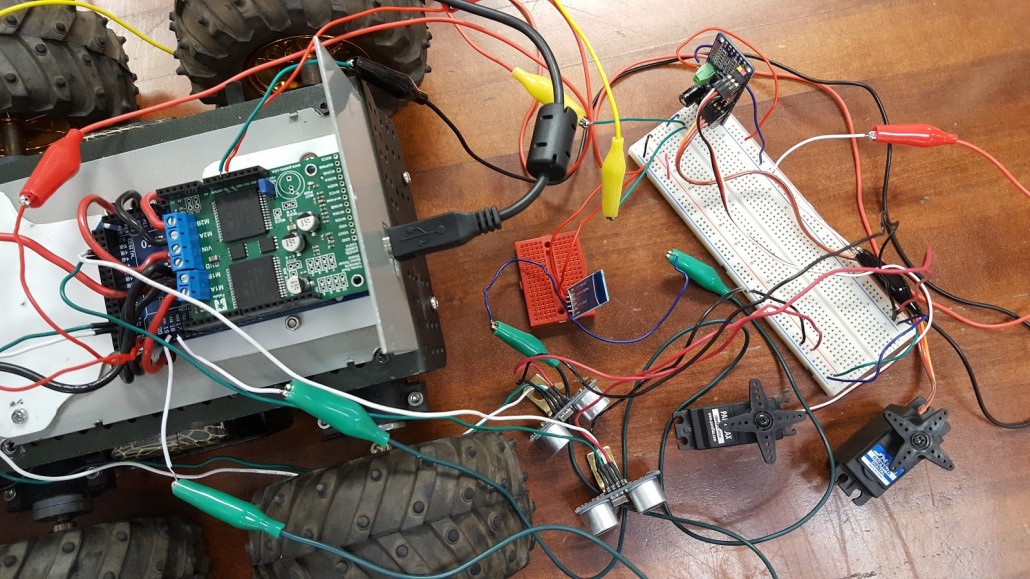
Breadboard

2                                                            Figure 14 – Breadboard

PCB Schematic

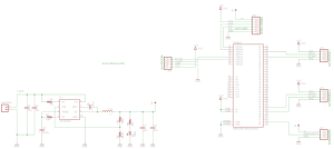
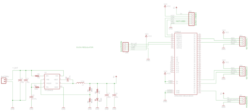
1                                                              Figure 15 – PCB System Schematic

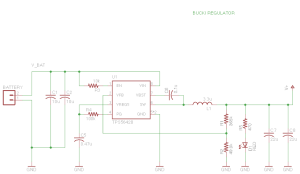
2                                                                Figure 16 – Buck Regulator

PCB Layout

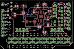
9                                                             Figure 17 – PCB Layout

The pathfinder project needs a custom PCB to integrate all the electronic components, which included: VNH5019 motor shield, PCA9685 Servo PWM Controller, two servos, six DC motors, HC-06 Bluetooth Module, two HC-SR04 ultrasonic sensors, two LED Headlights. The custom PCB also take advantage of the leftover pins on the Arduino Mega. A buck regulator is required to step down the voltage from 12 V to 5.5 V in order to protect the servo driver. The advantage of using buck regulator over the voltage regulator is to keep a constant current.

For further details about the PCB system schematic design and layout, refer to:

Spring 2016 Pathfinder: PCB System Schematic

Spring 2016 Pathfinder: Design and Manufacturing – PCB Layout

Hardware Design

Overall Design
Picture1                                                           Figure 18 – Pathfinder overall Design

3D illustration                                                            Figure 19 – 3D Illustration

3D illustratioin2                                                            Figure 20 – Exploded View

**Rocker Bogie System**

6                                                                 Figure 21 – Rocker Bogie System

f15                                                              Figure 22 – Exploded View

**Tilt System**

16                                                                       Figure 23 – Tilt System

15                                                                    Figure 24 – Exploded View

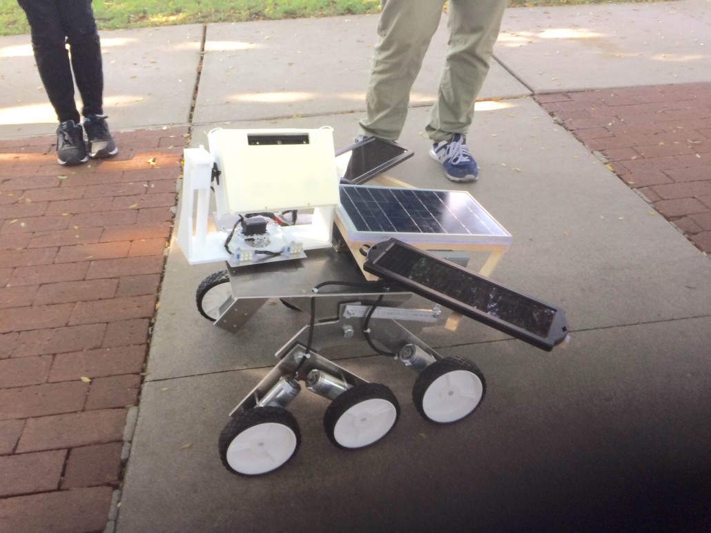
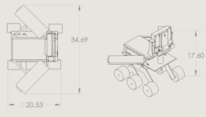
These above pictures demonstrate the hardware design from the overall 3D models to breakdowns parts of the pathfinder rover design.

The goal of Spring 2016’s Pathfinder is to hold a Google Tango tablet, phone, solar panels in the shape of the Arxterra logo, a tilt system, and an electronic box. To best traverse obstacles, a rocker bogie suspension system design was chosen, with a top surface area of 12in x 18in. Modeled after ServoCity’s runt rover, the chassis was scaled to meet the surface area required for the above mentioned parts. The tilt system was designed to hold the tablet, phone and tilt servo. Lastly, all parts were modeled on the chassis.

For further details of the hardware design, refer to:

Spring 2016 Pathfinder Design and Manufacturing – Tilt System Design

Spring 2016 Pathfinder Design and Manufacturing – Tilt System Finalized Design

Spring 2016 Pathfinder Design and Manufacturing – Rocker Bogie Suspension System Design

Spring 2016 Pathfinder: Design and Manufacturing – Chassis Selection Through the Iterative Design Loop

Software Design

Software System Block Diagram
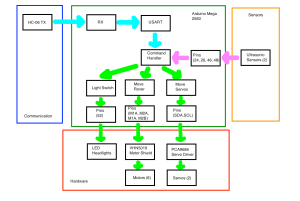
1                                                        Figure 25 – Software System Block Diagram

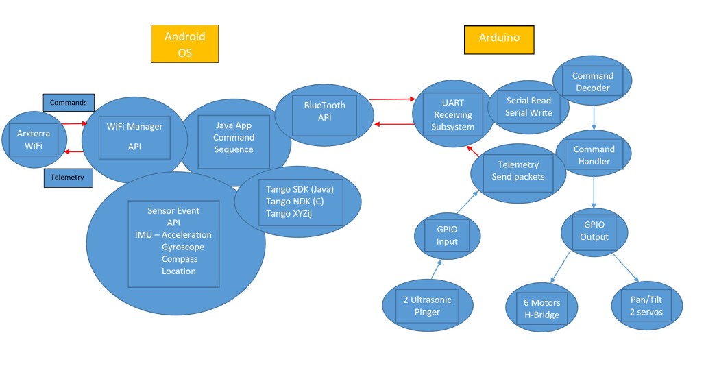
The software design follows the system block diagram and focus on the subsystem level software modules development.

For further details on how each software modules works, refer to:

Spring 2016 Pathfinder: Software Design

For reference of Arduino code controlling motors and servos through coolterm, refer to:

Spring 2016 Pathfinder: Software Design

For reference of controlling motors through Arxterra, refer to

Spring 2016 Pathfinder: Bluetooth Communication with the Arxterra App

For reference of controlling servos through Arxterra, refer to

Spring 2016 Pathfinder: Arxterra Servo Control for Pan and Tilt

Verification and Validation Test Plans

Verification and Test Plans are required to prove that the project can meet the L1/L2 requirements.

Since our team received new requirements of building a new pathfinder in a short period of time, many of the verification tests had not yet been done due to the heavy work of manufacturing. The project final demo then was been used for some of the verification and validation tests.

For more details of the verification matrix and Validation Test Plans, refer to the “project resource

Project Update

Work Breakdown Structure
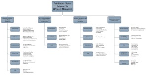
WBS                                                              Figure 26 – Work Breakdown Structure

This work breakdown structure demonstrates all the work needed to be done for this project Pathfinder Rover. There are four branches that indicates different job duties and division works assigned to the system and subsystem engineers.

Resource Report

Mass Report & Power report

The mass report and power report are both missing because our team did not have enough time to update the reports for the new pathfinder. 

For previous mass report and power report, refer to “CDR presentaion” in Project resource file

Cost Report

cost report


Project Schedule and Progress

1 2 3 4 5

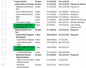
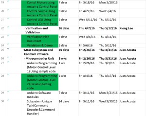
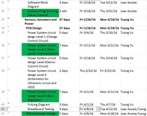
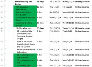
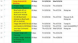
Above is the final schedule for this spring 2016 Pathfinder Rover Project. The Project Overall duration is 65 school days. This schedule was made and managed by the project manager to keep on track of the project overall progress. The tasks highlighted in green are the major tasks our team accomplished during this semester, while those tasks highlighted in yellow are the tasks our team had difficulties and could not accomplish them on time. In this semester, our team was able to fully tested, debugged and implemented the code for motors control and servos control for pan and tilt system through both coolterm and Arxterra. Another progress we made was to build a new generation of pathfinder by implementing Rocker Bogie Suspension System and solar panels self-charging capability. However, the team had troubles of implementing Project tango modules to the pathfinder.

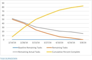
BurnDown

BD

Completion

completion

The Project Overall completion is 83%.


Concluding Thoughts:

Lessons learned the hard way

  1. The major problem our Pathfinder Team had was Project Tango. It is fairly new and has many limitations on sensor abilities as well. After we done the research of project tango, we realized that it requires extensive knowledge of Java programming and Android App development to accomplish the mission. Unfortunately none of the team member had that experience.
  2. The second issue we had was that the project requirements kept changing during the beginning of the semester. The mission profile went from daytime at desert terrain to night time at CSULB campus. The is due to the fact that the tango’s IR sensors for depth perception is generally restricted to indoor environments (sun and incandescent IR light can drown out structured light sensing).
  3. The third issue we had was that the manufacturing process for the aluminum sheets took too long from the rough cutting to mill finish. The aluminum was cut by hand by group members that weren’t supposed to be involved. As the project manager, I decided to let the the whole team contribute on assembling the parts during the final week to accomplish the mission. But the downside was that we did not have enough time to redo some of the verification tests for new chassis and motors.
  4. It is hard to manage the conflicts among cost, schedule and performance. Our pathfinder team was having trouble on getting all the parts we wanted. We were approved to get an extra budget of $300, yet, we still did not have enough money to get better wheels. The wheels problem lowered our project performance on obstacle climbing test.

Future Plans for Pathfinder

  1. Keep working on Project Tango. It is recommended to have 1 or 2 team members who has good knowledge of Android App development or some students from computer science major who can commit to help this project.
  2. The experimental results in this blog post need to be updated.
  3. The Mass and Power report need to be updated.
  4. Change the wheels on the pathfinder.
  5. Improve the encasement for tango (sealed, waterproof). This pathfinder can be taken to the wild area.
  6. Think of a way to rearrange the weight on top of the pathfinder. One issue we had was that the weight distribution was more on the backside, therefore it gives unstableness when climbing the obstacles.

Future Plans for project manager

  1. I think the project manager needs to be trained on their project management skills. Learning how to manage the cost, schedule and performance. A good way is to have a guest speaker give a short lecture on that.
  2. Project manager should post a project update blog post every two weeks. It can help them to keep on track of the project progress and schedules. It is also Easy for team member to follow.

Project Resource Files

Project Video

PDR

CDR

Project Schedule

Verification and Validation Documents

Solidworks File

Fritzing File

EagleCAD File

Arduino Code

PCB Library

Bill of Material(1)

Bill of Material(2)


Spring 2016 Pathfinder: Arxterra Servo Control for Pan and Tilt

IMG_3244

By:

Xiong Lee (Mission, System and Test)

Table of Contents

Objective:

After test and calibrating our servos from the earlier blog post found here, we then needed the servos to run through the arxterra app.  The arxterra app already has a built in button to control panning and tilting. All we need to do is have the code turn our servos when arxterra is sending the command to pan and tilt. After configuring the code to do these actions, we were able to control the pan and tilt servos.

Equipment:

  1. Arduino (we used the Mega but the uno can suffice)
  2. Servo Driver (PCA 9685)
  3. Battery (we used 7.4 v)
  4. Arduino IDE
  5. Servos
  6. Phone

Code:

After wiring up circuit, we have to use the servo code to control our servos found on blog post above. From the code you see at the blog post, we have to convert pulse length to degrees. So when we’re getting the commands from the arxterra, we can convert the numbers to degrees depending on the servo max and min. The only way to control these servos are through the arxterra control panel.

else if (cmd == CAMERA_MOVE){

     pulsedegree = map(data[4], 0, 180, SERVOMIN, SERVOMAX);

     pwm.setPWM(9,0, pulsedegree);

     pulsedegree = map(data[6], 0, 180, SERVOMIN, SERVOMAX);

     pwm.setPWM(8,0,pulsedegree);  

     delay(1000);   

     }

The data[4] and data [6] are the turn degrees that arxterra sends. Data 4 pertains to the pan degrees and data 5 is the tilt degrees.

Conclusion:

In conclusion we were able to control the servos for the pan and tilt with the control panel on the arxterra app. With the command line above, we were able to convert our servos to degrees and have it turn accordingly. The code above is on the command page with the move command.

Spring 2016 Pathfinder: Mission Profile and Project Objective Update

By:

Peiyuan Xu (Project Manager)

Table of Contents

Mission Profile Update

The team received the PDR debrief from meeting with the customer, student assistant and the president. One of the comments they had was that the mission profile was unclear. The team then develop a new mission profile which will clarify the confusion of the current one.


mission WiFi Stength

Mission Profile:

Since our Pathfinder Rover will be tested at the entire CSULB campus. We need to find out where there is the best Wi-Fi signal  in order to gain the stable video stream on Arxterra. The system engineer Xiong Lee was able to use an android App called Wi-Fi Maximiser to map out the  Wi-Fi signal strength around CSULB campus.  Based on the strength of the Wi-Fi signal, our mission will be narrowed down to the area covered with green on the map. We suggest the customer not to go through the area covered with red because there might be some packet loss and signal lag around the area. We also think this Wi-Fi signal strength map can be useful for other EE 400D project in which case they need to explore the CSULB campus as well.


Project Objective Update

The team received new requirements from the customer to design a new Pathfinder Prototype using Rocker Bogie Suspension system. Therefore, the project objective will be changed to accomplish the new requirements

Previous Project Objective:

The spring 2016 Pathfinder Rover was inspired by the design of NASA’s MARs Exploration Rover-“Sojourner”. The purpose of this Rover is to explore the beauty of CSULB campus at night in a self-sufficient way. The Pathfinder is allowed to have the solar panel charging the battery for up to 8 hours during the day time. Then the customer will spend 4 hours at night walking and exploring with the Pathfinder . The customer can use Arxterra control panel on the PC to navigate the Rover by using the cursor to click a point on the map. This generation of Pathfinder Rover is designed to test and implement SLAM (Simultaneous Localization and Mapping) technology for autonomous vehicles.

Current Project Objective:

The spring 2016 Pathfinder Rover was inspired by NASA’s MARs Exploration Rover-“Sojourner”. The profile for this semester’s project is to imitate the design of “Sojourner” Rover to prototype a new generation of Pathfinder Rover that implements the Rocker Bogie Suspension System as well as being self-sufficient by using solar panels. The Pathfinder is allowed to have the solar panels charging the battery for up to 8 hours during the day time. Then the customer can spend up to 4 hours at night walking and exploring with the Pathfinder. Ultimately, The customer can use Arxterra control panel on the PC to navigate the Rover by using the cursor to click a point on the map. This generation of Pathfinder Rover is also designed to test and implement SLAM (Simultaneous Localization and Mapping) technology for autonomous vehicles.


Spring 2016 Pathfinder: System Block Diagram & Interface Matrix

By:

Xiong Lee (Missions, Systems and Test)


System Block Diagram

1


The picture above shows a block diagram of our pathfinder. These are the hardware that we are using to run our pathfinder. From this diagram, it shows how many pins we are allocating for each hardware. For example, we are using TX, RX, 5v, and Gnd for the bluetooth module (HC-06) that we are using. This shows each component we are using and what pins should be allocated to those specific component.

Here is a basic walkthrough of our project. We are using the arduino mega and we have the bluetooth module (HC-06) connected to the pins TX2, RX2, 5v, and Gnd. The arxterra app is then connected to the Google tango via wi-fi and the tango is connected to HC-06 via bluetooth. The next component we have is the LED’s. We allocated 2 pins total for these two LED. On top of our arduino is our motor shield. It is connected to 8 digital pins and 2 analog pins. The next thing connected to our arduino is the servo driver. We have allocated pin 21 and 20 for the servo driver. Through the servo driver, our pan and tilt servo is connected on it. On the side, we have our solar panel and battery connected to the charge controller and then the charge controller is connected to the motor shield and buck regulator. The buck regulator (step down voltage regulator) is then connected to the servo driver.

For more in depth view on which pins are used on the arduino, look at the interface definition table below.

Interface Matrix

2 3

4


Conclusion

These diagrams are our system block and interface diagrams. The only concluding though I have is to make these diagrams readable and easy for the eye during the presentation. This was one of the problems many groups had this semester. Other than that, the other groups also had good diagrams. If you need more references as to how you should do these diagrams, look at the other groups too.

Source Materials

  1. The VHN5019 Motor shield                                                                              https://www.pololu.com/product/2502                                                                 https://www.pololu.com/docs/0J49/3.c
  2. The PCA9685 Servo driver                                                                                            https://www.adafruit.com/product/815

Spring 2016 Pathfinder: Software Design

By:

Juan Acosta (Electronics & Control – MCU Subsystem and Firmware)


Table of Contents

Software System Block Diagram:

1

The figure above depicts the software side of the Pathfinder. First, commands will be sent through Bluetooth and received through Serial communication ports on the Arduino Mega. Then the Command Handler will decode the telemetry packets being sent and appropriate an action unique to each packet ID. The VHN5019 Motor shield will implement the movement of the Pathfinder. The PCA9685 Servo driver will control the pan and tilt servos. Additionally, the use of ultrasonic sensors will provide feedback for obstacle detection or collision. Lastly, we will create a custom Arxterra command to control our L.E.D. headlights.

Arduino Code for controlling servos through Coolterm:

The following code snippet was used to test the functionality of the PCA9685 Servo Driver and how to gain a better understanding for servo control. For testing purposes, we used the Coolterm application on a laptop to demonstrate wireless bluetooth control of the servos. The code provided will help future projects in the process of initializing bluetooth communication, transmission of data, and later the creation of custom Arxterra commands.

///////////////////////////////////////////////////////////////////////////////

// The following code was written, tested and debugged by Juan Acosta for

// testing pan and tilt servo control through two wire communication (I2C)

// using the HC-06 to implement commands being sent from the COOLTERM application

// from a laptop or phone to the arduino.

// Group: Pathfinder Spring 2016

// Electronics and Control:  Juan Acosta (MCU Subsystem and Control Firmware)

///////////////////////////////////////////////////////////////////////////////

#include <Wire.h>

#include <Adafruit_PWMServoDriver.h>

///////////////////////////////////////////////////////////////////////////////

// following are connections required for HC06 module:

// connect BT module TX to RX0

// connect BT module RX to TX0

// connect BT Vcc to 5V, GND to GND

///////////////////////////////////////////////////////////////////////////////

// following are connections required for PCA9685 Servo Driver:

// connect V+ to 5V, GND to GND (servo power terminals)

// connect Vcc to 5V, GND to GND

// connect SDA to analog pin A4 (required for I2C bus control on arduino UNO)

// if using arduino MEGA SDA has dedicated pin on PIN20

// connect SCL to analog pin A5 (required for I2C bus control on arduino UNO)

// if using arduino MEGA SCL has dedicated pin on PIN21

// connect pan servo plug to 9

// connect tilt servo plug to 11

///////////////////////////////////////////////////////////////////////////////

Adafruit_PWMServoDriver pwm = Adafruit_PWMServoDriver();

#define SERVOMIN  0          // this is the ‘minimum’ pulse length count

                             // (for Pan = facing left)(for tilt = facing down)

#define SERVOMAX  500        // this is the ‘maximum’ pulse length count

                             // (for Pan = facing right)(for tilt = facing up)

// The limits for the pan will be from 0 degrees to 180 degrees of view in steps

// of 45

// The limits for the tilt will be from 45 degrees to 135 degrees of view in

// steps of 45

void setup() {

  Serial2.begin(9600);       // set the data rate for the Serial Port

  pwm.begin();

  pwm.setPWMFreq(60);       // Analog servos run at ~60 Hz updates

  yield();                 

}

// Character commands list:

//      (“Send ‘0’ pan facing left (180 degrees)”);

//      (“Send ‘1’ pan facing diagonal left (135 degrees)”);

//      (“Send ‘2’ pan facing center (90′ degrees)”);

//      (“Send ‘3’ pan facing diagonal right (45′ degrees)”);

//      (“Send ‘4’ pan facing right (0′ degrees)”);

//      (“Send ‘5’ tilt facing down (-45 degrees)”);

//      (“Send ‘6’ tilt facing center (0 degrees)”);

//      (“Send ‘7’ tilt facing up (45 degrees)”);

char a; // stores incoming character from other device (phone, tablet, or laptop)

void loop()

{

   if (Serial2.available())        // if text arrived in from hardware serial…

  {

    a=(Serial2.read());

    if (a==’4′)                   // face right

    {

      Serial.println(” pan facing right (0′ degrees)”);

  for (uint16_t pulselen = SERVOMIN; pulselen < SERVOMAX; pulselen++) {

    pwm.setPWM(9, 0, pulselen);

  }

  delay(1000);

    }

    if (a==’3′)         // face right at an angle (diagonal right)

    {

      Serial.println(“pan facing diagonal right (45′ degrees)”);

  for (uint16_t pulselen = SERVOMIN; pulselen < 375; pulselen++) {

    pwm.setPWM(9, 0, pulselen);   

  }

  delay(1000);

    }

    if (a==’2′)         // face straight (centered)

    {

      Serial.println(“pan facing center (90′ degrees)”);

  for (uint16_t pulselen = SERVOMIN; pulselen < 250; pulselen++) {

    pwm.setPWM(9,0,pulselen);

  }

  delay(1000);

    }

   if (a==’0′)         // face left

   {

      Serial.println(“pan facing left (180 degrees)”);

  for (uint16_t pulselen = SERVOMAX; pulselen > SERVOMIN; pulselen–) {

    pwm.setPWM(9, 0, pulselen);

  }

  delay(1000);

   }

   if (a==’1′)         // face left at an angle (diagonal left)

   {

      Serial.println(” pan facing diagonal left (135 degrees)”);

  for (uint16_t pulselen = SERVOMAX; pulselen > 125; pulselen–) {

    pwm.setPWM(9, 0, pulselen);

  }

  delay(1000);

   }

   if (a==’5′)         // face down (-45 degrees)

   {

      Serial.println(“tilt facing down (-45 degrees)”);

  for (uint16_t pulselen = SERVOMAX; pulselen > 125; pulselen–) {

    pwm.setPWM(11, 0, pulselen);

  }

  delay(1000);

   }

   if (a==’6′)         // face straight (centered)

    {

      Serial.println(“tilt facing center (0 degrees)”);

  for (uint16_t pulselen = SERVOMIN; pulselen < 250; pulselen++) {

    pwm.setPWM(11,0,pulselen);

  }

  delay(1000);

    }

    if (a==’7′)         // face right at an angle (diagonal right)

    {

      Serial.println(“tilt facing up (45 degrees)”);

  for (uint16_t pulselen = SERVOMIN; pulselen < 375; pulselen++) {

    pwm.setPWM(11, 0, pulselen);   

  }

  delay(1000);

    }

   if (a==’?’)        // commands list

    {

      Serial.println(“Send ‘0’ pan facing left (180 degrees)”);

      Serial.println(“Send ‘1’ pan facing diagonal left (135 degrees)”);

      Serial.println(“Send ‘2’ pan facing center (90′ degrees)”);

      Serial.println(“Send ‘3’ pan facing diagonal right (45′ degrees)”);

      Serial.println(“Send ‘4’ pan facing right (0′ degrees)”);


      Serial.println(“Send ‘5’ tilt facing down (-45 degrees)”);

      Serial.println(“Send ‘6’ tilt facing center (0 degrees)”);

      Serial.println(“Send ‘7’ tilt facing up (45 degrees)”);

    }     

    // you can add more “if” statements with other characters to add more commands

  }

}

Arduino code for controlling Motors through Coolterm

The following code snippet was used to demonstrate the functionality of the VHN5019 Motor shield and how to gain a better understanding of DC motor control. For testing purposes, we used the Coolterm application on a laptop or cell phone to demonstrate wireless bluetooth control of the pathfinder’s movements. The code provided will help future projects in the process of initializing bluetooth communication, transmission of data, and later the creation of custom Arxterra commands.

///////////////////////////////////////////////////////////////////////////////

// The following code was written, tested and debugged by Juan Acosta for

// testing the functionality of the VHN5019 Motor Shield and how the six motors

// rotate will dictate which way the rover moves.

// using the HC-06 to implement commands being sent from the COOLTERM application

// from a laptop or phone to the arduino.

// Group: Pathfinder Spring 2016

// Electronics and Control:  Juan Acosta (MCU Subsystem and Control Firmware)

///////////////////////////////////////////////////////////////////////////////

#include “DualVNH5019MotorShield.h”

DualVNH5019MotorShield md;

void stopIfFault()

{

  if (md.getM1Fault())

  {

    Serial.println(“M1 fault”);

    while(1);

  }

  if (md.getM2Fault())

  {

    Serial.println(“M2 fault”);

    while(1);

  }

}

void setup()

{

  Serial.begin(115200);

  Serial.println(“Dual VNH5019 Motor Shield”);

  md.init();

  Serial.begin(9600);

}

char a; // stores incoming command from device into variable a

void loop()

{

   if (Serial.available())

  // if text arrived in from hardware serial…

  {

    a=(Serial.read());

    if (a==’?’)//////// send commands list

    Serial.print(“Send a 1 to move the pathfinder forward”);

    Serial.print(“Send a 2 to stop the pathfinder”);

    Serial.print(“Send a 3 to rotate the pathfinder by 180 degrees”);

    Serial.print(“Send a 4 to make the pathfinder reverse”);

    if (a==’1′)/////// move the pathfinder forward by sending a 1

    {

      int o=0; /////// stop the rover before moving forward

     md.setM1Speed(o);

     md.setM2Speed(o);

     for (int p = 0; p <= 300; p++)

  {

      md.setM1Speed(p);

     md.setM2Speed(p);

      Serial.print(“Moving the Pathfinder forward “);   

  }

    }

 if (a==’2′)///////////////// stop the wheels by sending a 2

 {

    int i=0; 

    md.setM1Speed(i);

    md.setM2Speed(i);

      Serial.print(“Stop the Pathfinder: “);

  }

    if (a==’3′)///////////////// rotate 180 degrees 

    {

    Serial.print(“Rotating 180 degrees “);

    int c=0;////////////////// stop rover before rotating

    md.setM1Speed(c);

    md.setM2Speed(c);

  for (int m = 0; m <= 300; m++)  //////// rotate rover 180 degrees

  {

    md.setM1Speed(m);

    md.setM2Speed(m-300);

    delay(2.3);

    int k=0;

    md.setM1Speed(k);

    md.setM2Speed(k);

    }

    }

if (a==’4′)/////// make the pathfinder reverse by sending a 4

{

  Serial.print(“The pathfinder will reverse”);

      int l=0; /////// stop the rover before reversing

     md.setM1Speed(l);

     md.setM2Speed(l);

     for (int j = 0; j <= 300; j++)

  {

      md.setM1Speed(j-600);

     md.setM2Speed(j-600);   

  }

    }

  }

}

Conclusion:

Applying what we now have learned, we are ready for software implementation through Arxterra including custom commands. Once we had each module working separately, putting them all together to form the pathfinders software system design will require a reasonable amount of testing and debugging since we now have most of it done working without Arxterra. All that is left is the custom command encoding.

Source Materials:

– Coolterm:

http://freeware.the-meiers.org

– Spring 2016 Pathfinder: Subsystem Design

http://arxterra.com/spring-2016-pathfinder-subsystem-design/

– Arxterra Custom Commands

https://www.youtube.com/watch?v=G5vRvecFA3A

https://www.youtube.com/watch?v=h4KgktOa8-A

Spring 2016 Pathfinder: Design and Manufacturing – Chassis Selection Through the Iterative Design Loop


3D illustration

By:

Lindsay Levanas (Design and Manufacturing)

Table of Contents

Introduction

Although all previous posts regarding Spring 2016 Pathfinder’s chassis have focused on the rocker bogie suspension system design, the use of a Wild Thumper chassis was also considered and so it is worth documenting the iterative design loop that lead to the final product. This report will outline the decisions that had to be made and their impact on the design.

Initial Requirements – Rocker Bogie Suspension System

To start with, Spring 2016 Pathfinder’s level 1 terrain requirement is to traverse the CSULB campus at night.1 To this end, the rocker bogie suspension system was chosen and implemented as a level 2 requirement2 and a basic rocker bogie suspension system was modeled as an example.3

1

Figure 1.  Basic Model of rocker bogie system

The idea modeled, the next step was to research into physical implementation.

Initial Research – Rocker Bogie Suspension System

As rocker bogie suspension systems require particular dimensions to function properly, it was decided that purchasing a working model would be best. Therefore, rocker bogie chassis were researched and only one was found to be purchasable: the Bogie Runt Rover from ServoCity.4

2

Figure 2.  Bogie Runt Rover

Trade-off Study – Wild Thumper vs. Bogie Runt Rover

Having found a rocker bogie suspension system, the next step was to conduct a trade-off study between that and a Wild Thumper chassis. Note that Spring 2016’s Pathfinder is meant to improve upon the design that came before it and that this is where the Wild Thumper chassis is coming from.5 Below illustrated the initial trade-off study between the two chassis.4,8,9,10

3

Figure 3.   Chassis Trade-Off Study

Results – Wild Thumper

After listing the different aspects of the two chassis systems, the important factors need to be clarified. To start with, the width of the tilt system (at least 10.48in)6 is dictated by the use of a Google Tango Tablet, and so needs to be considered. Also, the weight of the load that Spring 2016’s Pathfinder will carry is at least 2.45lbs from the tilt system alone as shown below.

4

Figure 4. Tilt System Mass Properties

On top of all this, the chassis needs to be able to hold the pan system, electronics, electronic protection box, batteries and solar panels. Although at this point in the design process these additional parts had yet to be finalized, the concern of going over the weigh capacity (and surface area) of the Runt Rover was still relevant and so was taken into consideration when choosing a chassis. Also considered was the terrain the chassis could handle under load.

Given that the Runt Rover base was smaller then the tilt system width, and that it could only carry up to 4lbs on smooth terrain, the Wild Thumper was chosen to be Pathfinder’s chassis at this time.

5

Figure 5.  Wild Thumper Chassis

New Resource Option – Rocker Bogie Suspension System

Not long after the Wild Thumper was chosen as the chassis, a new resource was made available to Spring 2016’s Pathfinder team. This resource was aluminum cutting and milling. This meant that the Runt Rover previously viewed as too small could be modeled in Solidworks, simplified, doubled in size, and cut out of aluminum. To see how this would compare to the Wild Thumper, the proposed rocker bogie system was modeled in Solidworks so that size and weight could be properly estimated.7

6

Figure 6.  Rocker Bogie System

Trade-off Study – Wild Thumper vs. Rocker Bogie Suspension System


7

The above picture compares the specs of both chassis

Conclusion and Future Plans

As the Rocker Bogie design allowed for 145.688 more square inches of top surface area and 9.04 more inches of obstacle avoidance clearance for a loss of only 1lb of weight tolerance and 1.5lbs of unloaded weight, the Rocker Bogie design was chosen as Spring 2016’s final Pathfinder chassis. A sample model of the chassis with its future load is shown below.

3D illustration

Source Materials:

  1. Spring 2016 Pathfinder Preliminary Design Documentation, Level 1 Requirement, 2/19/16 http://arxterra.com/spring-2016-pathfinder-preliminary-design-documentation/
  2. Spring 2016 Pathfinder Preliminary Design Documentation, System Requirements (Level 2 Requirements), 2/19/16 http://arxterra.com/spring-2016-pathfinder-preliminary-design-documentation/
  3. Spring 2016 Pathfinder Preliminary Design Documentation, Mechanical Design, 2/19/16 http://arxterra.com/spring-2016-pathfinder-preliminary-design-documentation/
  4. Bogie Runt Rover https://www.servocity.com/html/bogie_runt_rovertm__637162_.html#.VvmvlJGprwI
  5. Pathfinder Final Documentation, Pathfinder Preferred Design, 12/12/2014 http://arxterra.com/pathfinder-final-documentation/
  6. Spring 2016 Pathfinder Design and Manufacturing – Tilt System Design, Tilt Base, 3/9/2016 http://arxterra.com/pathfinder-design-and-manufacturing-tilt-system-design/
  7. Spring 2016 Pathfinder Design and Manufacturing – Rocker Bogie Suspension System Design, 3/30/2016 http://arxterra.com/2016-pathfinder-design-and-manufacturing-rocker-bogie-suspension-system-design/
  8. 6WD dimension http://cdn.sparkfun.com/datasheets/Robotics/6WD%20dimension.jpg
  9. Pololu – Dagu Wild Thumper 6WD All-Terrain Chassis, Black, 75:1, Specifications, https://www.pololu.com/product/1563
  10. Robotshop.com/media/files/pdf/schematics, http://www.robotshop.com/media/files/pdf/schematics-637162.pdf

Spring 2016 Pathfinder: Design and Manufacturing – PCB Layout

9

By:

Lindsay Levanas (Design and Manufacturing)

Table of Contents

Introduction

This report will serve to document how the Spring 2016 Pathfinder’s PCB layout was designed in EAGLE7.5.0 Light. Reference to the PCB schematic outlined in Spring 2016 Pathfinder: PCB System Schematic1 will be mentioned, as well as safety precautions from outside sources. Note that all components will be surface mounted, and all jumper pins will be through hole.

Reference – PCB Schematic

Although Eagle is designed to carry over the component’s wiring from the schematic to the board’s layout (then called airwires), the connections between pins can sometimes be hard to see. For example, in the illustration below, where does the top airwire (the thin yellow line) go? Does it connect straight to the bottom pin of JP4? Or does it connect to one of JP4’s other pins too?

1

Therefore, in addition to rotating the part (which can be hard to keep track of), the original schematic can also be referenced to verify that the proper connections are being made.

2

Using the above part as an example, the equivalent part in the schematic can then be used as a reference.

3

Since pins 2 and 3 are accounted for with single connections and ground does not use an airwire, the top connection can then only be to pin 1.

Note that this process can be used for any component where the connection seems unclear. Now that a general idea has been obtained for the PCB’s wiring, safely measures can be looked into next.

Safety – Current Amount and Trace Width

To ensure that the PCB is able to function properly, the amount of current through the circuit needs to be considered. If the traces are too small for the amount of current they need to carry, then they run the danger of burning out.2 According to the Power Test3 the max amount of current Spring 2016 Pathfinder’s PCB will be carrying is 140mA.

4

Using a trace width calculator (shows above) for PCBs,4  the minimum desired trace width can be found.

Note that as Spring 2016 Pathfinder’s PCB traces will be on external layers, the width of the trace needs to be no smaller then .393mils.

To check the trace width in Eagle, right click on any trace and select Properties. In the pop up box, check the width number against the grid units. This will tell you what units the width is being measured in as Eagle bases all numbers on the grid units.

5

As is illustrated above, the traces are set to have a width of 16mils. As this is larger then the trace width calculations, the trace sizes do not have to be changed.

Alignment – Buck Converter

For optimal functionality of the buck converter, the TPS56428 chip needs to be considered. This means that the circuit layout included in the chip’s datasheet5 must be followed, or the PCB may not work. Below is the proper setup outlined in the datasheet followed by the corresponding PCB layout.

6


7

Conclusion and Future Plans

In conclusion, Spring 2016 Pathfinder’s PCB will follow the corresponding PCB schematic, current safety precautions and proper chip layout. After fabrication, the next step will be to solder all of the parts onto the board.

8


Source Materials:

  1. Spring 2016 Pathfinder: PCB System Schematic, Custom PCB Schematic, 1/3/2016 http://arxterra.com/spring-2016-pathfinder-pcb-system-schematic/
  2. Reference Designer Calculations, PCB Trace Width Calculator, 2009 http://www.referencedesigner.com/cal/cal_06.php
  3. Spring 2016 Pathfinder: PCB System Schematic, Power Test, 1/3/2016 http://arxterra.com/spring-2016-pathfinder-pcb-system-schematic/
  4. PCB Printed Circuit Board File Creation Calculator, Trace Width Website Calculator, 2007 http://www.4pcb.com/trace-width-calculator.html
  5. Electronic Components Datasheet Search, TPS56428 Datasheet(PDF) 14 Page – Texas Instruments, April 2013,                                                                                                                   http://html.alldatasheet.com/html-pdf/523356/TI/TPS56428/428/14/TPS56428.html


Spring 2016 Pathfinder: PCB System Schematic

By:

Juan Acosta (Electronics & Control – MCU Subsystem and Firmware)

Tuong Vu     (Electronics & Control – Sensors, Actuators, and Power)

Table of Contents

Introduction:

Project Pathfinder required the use of an Arduino Mega, VNH5019 motor shield, PCA9685 Servo PWM Controller, two HC-SR04 ultrasonic sensors, two servos, six DC motors, HC-06 Bluetooth Module, LED Headlights, and Buck regulator. Each device we chose to use will help us accomplish our mission by meeting set level 1 and 2 requirements. For more information on testing and implementation of these devices, visit the previous blog post Spring 2016 Pathfinder: Subsystem Design

Custom PCB Schematic:

1


As discussed in our Subsystem Design, we decided that it would be best if we created a custom PCB that would allow us to take advantage of the leftover pins of the Arduino Mega. So in our custom PCB design, we aimed for a PCB that would interface with the Arduino Mega as a shield. In our PCB schematic we have allotted different headers for the two ultrasonic sensors needed for obstacle collision prevention, headers for the PCA9685 Servo Controller that we chose to safely power and drive our pan and tilt servos, headers for the HC-06 Bluetooth module needed for wireless communication, headers for the L.E.D. headlights needed for lighting, and TPS56428 buck regulator needed to step down voltage to 6 volts to protect the servo driver from 7.4V.

Buck Regulator:

2


The figure above focuses on the  buck regulator. We chose this buck regulator because it was found most efficient during testing. We used the data sheet provided by Texas Instruments in order to find the necessary resistance values for Resistors R1 and R2 which control the duty cycle needed for an output of 6 volts. For resistor R1 we got 355 K and 49.9 Kfor resistor R2. Aside from the necessary resistors and capacitors outlined in the guide sheet for the TPS56428, we also added capacitors C1 and C2 for noise cancellation and a red L.E.D. in series with resistor R5 in order to show when the circuit is on.

Headers:

3

The figure above focuses on the through hole headers we will be using to directly plug in our two ultrasonic sensors, headlight L.E.D.s, Bluetooth module, and servo driver.

Power test

During testing it was found that the max current draw for the PCA9685 servo driver was about 140 mA. The max current draw for the HC-06 bluetooth module was 25 mA. The max current draw for the L.E.D. headlights was 90 mA. The max current draw for the motors was 1 A. Lastly, the max current draw from the HC- SR04 ultrasonic sensors was 20 mA. For more info reference the Power Report below.

5

Keeping all of the voltage and current ratings of each device in mind will help during the routing of the custom PCB. Because different components need different current ratings to operate normally, the size of the traces in our PCB should reflect the amount of current that will go through these traces.


Source Materials:

– EagleCAD download:

http://www.cadsoftusa.com/download-eagle/

– TPS56428 buck regulator:

http://www.ti.com/product/TPS56428

– Spring 2016 Pathfinder: Subsystem Design

http://arxterra.com/spring-2016-pathfinder-subsystem-design/

Spring 2016 Pathfinder: Subsystem Design

By:

Juan Acosta (E&C – MCU Subsystem & Firmware)

Table of Contents

Fritzing Diagram

1

The fritzing schematic above depicts the circuit we used for testing the Wild Thumper Chassis’ motors, batteries, ultrasonic sensors, headlight L.E.D.s, servo driver along with servos, the motor shield along with the six motors driving the rover, and the Bluetooth module.

Earlier testing showed us that the Arduino Mega that we are using would leave us with plenty of unused pins, so we contemplated switching micro- controllers to the Arduino Uno. But after more experimentation we found the need for a servo driver to drive our pan and tilt system. We also found the need of digital pins to control the headlight L.E.D.s, communication pins for the Bluetooth module, and control pins for the ultrasonic sensors. Because of these needs, we determined that it would be best if we kept using the Arduino Mega.

As you can see from the fritzing diagram, the VHN5019 motor shield utilizes a little more than half of the Mega’s pins in order to drive the motors. So we decided to make another custom PCB shield that would serve to drive the HC-06 Bluetooth Module, the HCSR-04 ultrasonic sensors, the L.E.D. headlights, and the PCA9685 servo driver.

Breadboard:

2

The photo above depicts the circuit we used for testing the ultrasonic sensors, the servos, the Bluetooth module, the motor shield, and the servo driver.

Charging Circuit:

3

For our charge control circuit, we chose to use the Black Menba 20A 12V/24V Solar Charge/ Panel Battery Controller. We chose this solar charge controller because our initial charge controller design proved to be inoperable after thorough testing.

For initial design, reference previous blog post Spring 2016 Pathfinder Charging Control Circuit

Check more on blog post Spring 2016 Pathfinder Solar Panels Implementation

Led Headlights:

4

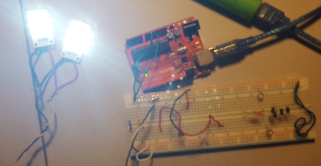
For our L.E.D. headlights, we chose to use the 6 Piranha 5V Led Light Panel Board. For this decision, we had only two factors: price and brightness. These L.E.D.s proved to be very bright meeting our expectations and making sure we met one of our requirements of aiding the pathfinder with lighting.

For more information see blog post Spring 2016 Pathfinder: LED Headlights


Source Materials:

– 6 Piranha 5V Led Light Panel Board White Night Lights Lamp Super Bright:

http://www.ebay.com/itm/181941929073?_trksid=p2057872.m2749.l2649&ssPageName=STRK%3AMEBIDX%3AIT

– Black Menba 20A 12V/24V Solar Charge/ Panel Battery Controller:

http://www.amazon.com/Black-Menba-Charge-Battery-Controller/dp/B012CHR3YY?ie=UTF8&psc=1&redirect=true&ref_=oh_aui_detailpage_o02_s01

– SMAKN® 16 Channel PWM/Servo Driver IIC interface-PCA9685 for arduino or Raspberry pi shield module servo shield:

http://www.amazon.com/SMAKN®-Channel-interface-PCA9685-arduino-Raspberry/dp/B012ES0HTY?ie=UTF8&psc=1&redirect=true&ref_=oh_aui_detailpage_o04_s00

– Spring 2016 Pathfinder: LED Headlights

http://arxterra.com/spring-2016-pathfinder-led-headlights/

– Spring 2016 Pathfinder Charging Control Circuit

http://arxterra.com/spring-2016-pathfinder-charging-control-circuit/


Spring 2016 Pathfinder: Project Tango Bluetooth API

tango_system

by:

Peiyuan Xu (Project Manager)

with contribution from:

Qianyi Tang (CSULB Computer Science Major Graduate Student)

Table of Contents

Introduction:

In our Project Tango system block diagram, one of the software module is to develop Bluetooth API in the Point Cloud App command sequence. This blog post is to show the approach of modifying point cloud App to pair and connect another device to Tango tablet through Bluetooth while still running Point Cloud.

Steps:

  1. Download and install Android Studio and Tango SDK
  2. Download the Point Cloud sample code and import it into Android Studio
  3. Connect the Tango tablet to the PC and enable the Android Debugging Bridge (ADB)
  4. Build and run the Point Cloud sample code. This would automatically install the App in Tango tablet
  5. Open project → app → Java → PointCloudActivity.java
  6. Open project → res → layout → activity_jpoint_cloud.xml
  7. Open project → res → values → strings.xml
  8. Breakdown and modify the code

The download instruction and links can be found here:


Code Breakdown and explanations:

1.Create the Bluetooth Button

Add the following code to “activity_jpoint_cloud.xml”
/******/
<Button
android:id=“@+id/bluetooth_button”
android:layout_width=“100dp”
android:layout_height=“wrap_content”
android:layout_above=“@+id/first_person_button”
android:layout_alignParentRight=“true”
android:layout_marginBottom=“5dp”
android:layout_marginRight=“5dp”
android:paddingRight=“5dp”
android:text=“@string/bluetooth” />

/******/

The code above will generate a button on the screen called”bluetooth” with the width of 100 dp(density-independent pixles). The “bluetooth” button will be placed above the “first_person_button” in the point cloud App.

2. Add the string of “bluetooth”

Next, go to “strings.xml”. Add one line of code:

/******/

</string>
<string name=”bluetooth”>bluetooth</string>

/******/

This gives the string type of “bluetooth” that can be called in the “activity_jpoint_cloud.xml”

3. Modify the code in point_cloud_activity

Now, go to “PointCloudActivity.java”. Add the following private classes:

/******/

private BluetoothAdapter BA;
private Set<BluetoothDevice>pairedDevices;
private boolean bluetoothFlag = false;

/******/

This declares Bluetooth adapter and store the list of paired Bluetooth devices. The last line is to store the state of Bluetooth(on/off) because the button can be used as a switch. By initial, it is set to off.

Add one line below:

/******/

BA = BluetoothAdapter.getDefaultAdapter();

/******/

This will assign the BluetoothAdapter.

Now go down to public classes, Add the following code:

/********/

public void bluetoothOn(){
if (!BA.isEnabled()) {
Intent turnOn = new Intent(BluetoothAdapter.ACTION_REQUEST_ENABLE);
startActivityForResult(turnOn, 0);
Toast.makeText(getApplicationContext(),”Turned on”,Toast.LENGTH_LONG).show();
visible();
}
else
{
Toast.makeText(getApplicationContext(),”Already on”, Toast.LENGTH_LONG).show();
}
}

/********/
This creates a function “bluetoothOn()” to turn on Bluetooth device and toast a message (“Turned on” or “Already on”).
/********/

public void bluetoothOff(){
BA.disable();
Toast.makeText(getApplicationContext(),”Turned off” ,Toast.LENGTH_LONG).show();
}

/********/

similarly, this creates a function “bluetoothOff()” to turn off Bluetooth device and toast a message “Turned off”

Next add the following lines below:

/********/

public  void visible(){
Intent getVisible = new Intent(BluetoothAdapter.ACTION_REQUEST_DISCOVERABLE);
startActivityForResult(getVisible, 0);
}

/********/

This will alter the Bluetooth device into visible state.

Continue adding these lines of code:

/********/

public void list(){
pairedDevices = BA.getBondedDevices();
ArrayList list = new ArrayList();

for(BluetoothDevice bt : pairedDevices)
list.add(bt.getName());
Toast.makeText(getApplicationContext(),”Showing Paired Devices”,Toast.LENGTH_SHORT).show();

}

/********/

This creates an array and add paired devices into list.

Finally, incorporate the main function:

/********/

@Override
public void onClick(View v) {
switch (v.getId()) {
case R.id.first_person_button:
mRenderer.setFirstPersonView();
break;
case R.id.third_person_button:
mRenderer.setThirdPersonView();
break;
case R.id.top_down_button:
mRenderer.setTopDownView();
break;
case R.id.bluetooth_button:
if(bluetoothFlag == false){
bluetoothOn();
bluetoothFlag = true;
}else {
bluetoothOff();
bluetoothFlag = false;
}
default:
Log.w(TAG, “Unrecognized button click.”);
}
}

/********/

This will create the click event handler. Based on different click event,it will switch viewer’s perspective and turn on/off Bluetooth device. In Bluetooth button section, this function will switch adapter between on/off.

IMG_3210

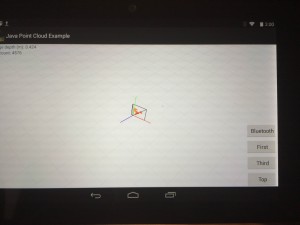
This is what the App will looks like after the modification. Notice the Button shows upon on the screen.

The modified Java Code can be downloaded here


Conclusion:

Modifying an existing Android App could be difficult since it requires good knowledge of Java Programming language as well as understand Android Studio platform. In this approach, I first did research and learn the basic Android App development and Java programming on Udacity website. Then I start modifying code in Point Cloud Existing App but unfortunately I crushed the App over and over again. After we got the Project Tango system block diagram from professor Hill, I start researching into Android Bluetooth API and trying to implement existing bluetooth sample code into the Point Cloud activity. Finally I successfully debug and run the modified App but the button itself does not work properly. After trying to debug the code, I found out that I need assistant from someone who develop the point cloud App to let me know where the breakpoints goes since I lost track of the breakpoints when stepping into the code.

This blog post does not show the fully functional Point Cloud App with Bluetooth feature, but can be documented and used as a good resource for individuals or groups from future class to continue developing the Java Point Cloud App.


Source Materials: