Spring 2016 Pathfinder: Project Tango Module#5 – Android to Arduino Via Bluetooth
By:
Xiong Lee (Missions, Systems and Test)
Table of Contents
Objective:
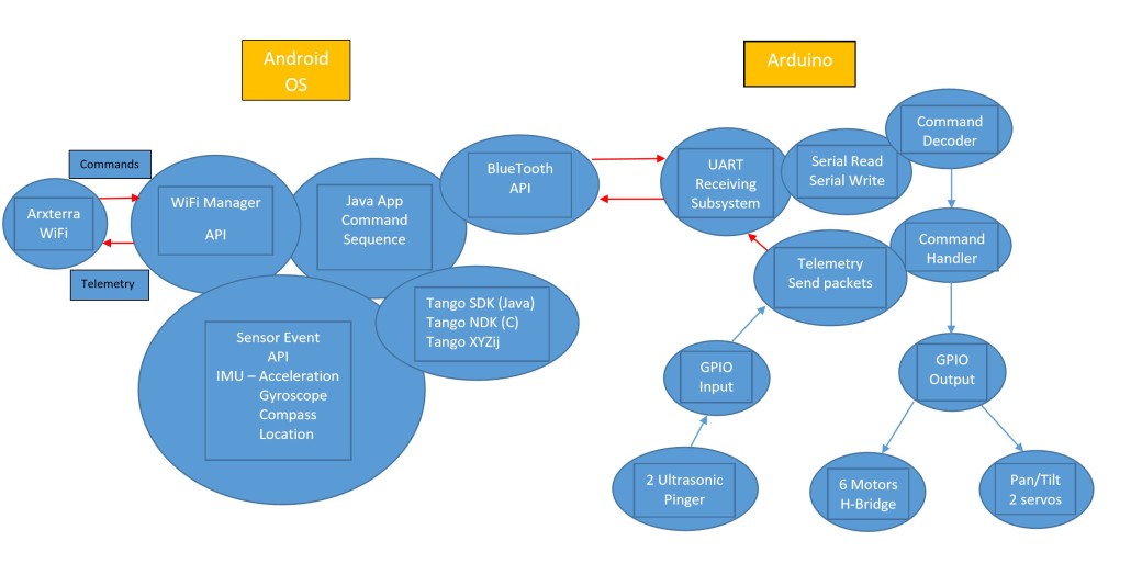
The objective of this test is to be able to send data from Android OS (Java, android studio) to the Arduino via Bluetooth. We use a simple open source code found on github to see if we can send data to the Arduino. The mission of this experiment is to move us closer to sending data from the Google tango (the Google tango is an Android OS device, therefore it uses java/Android studio) to the Arduino via Bluetooth.
Tools:
- Android Studio
- Arduino IDE
- Bluetooth Module (we used the HC-06)
- Arduino Uno / Mega
- LED
- Breadboard
- Android Phone with usb cord.
LED Test Java Code:
The Java code that is on github should work when you import it to Android studio. After importing the code into android studio, you have to wait and let android studio build the project. This will take from seconds to minutes. Once the gradle has been built, you can run the app. Before you run the app, you have to make sure your android phone is in debug mode (if you don’t know how to get it to debug mode, just google it with your version of phone) so you can connect it to android studio. Once your phone is connected to android studio, you can run it and choose your phone so the app can be on your phone. When have the app on your phone, then you need to go to the Arduino code. If you want to know more about the code, I suggest that you read and run through the code yourself to get an idea of how this app works.
The sample code can be found here
LED Test Arduino Code:
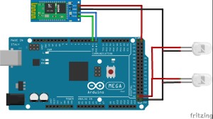
The Arduino code is also on github. It is at the bottom of this page here. Just copy and paste it to Arduino ide. Once you have it, go through the code so you know where to connect everything on the Arduino. Once you have connected everything the right way, verify the code and upload it to your Arduino. (Note: There are sometimes problem uploading code to the Arduino when the Bluetooth module is connected on the Arduino at the same time it is uploading. So to get over this problem, simply just take the Bluetooth module out before uploading the code and put it back on when the code has successfully been uploaded to the Arduino.)
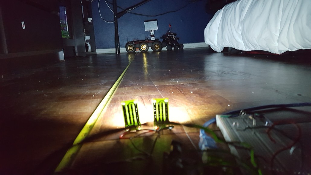
The first LED is connected to pin 9 and ground. The second LED is connected pin 2 and ground. The third LED is connected to pin 3 and ground. The RX on the Bluetooth module is connected to pin 11 and the TX is connected to pin 10. On the picture above, the button “Light Up” were pushed and as you can see, all the LEDs lit up.
Results:
When you have both the Java code and Arduino code, you should be able scan and find your Bluetooth module on the app. Once connected, turn on the LED lights by sliding the bars to the right or pressing all light up. Below is a picture showing how it should look like when you are lighting up the LED. In the end, we were able to send data from java to Arduino via Bluetooth. To take this a little further, we successfully move our pathfinder prototype with the app.

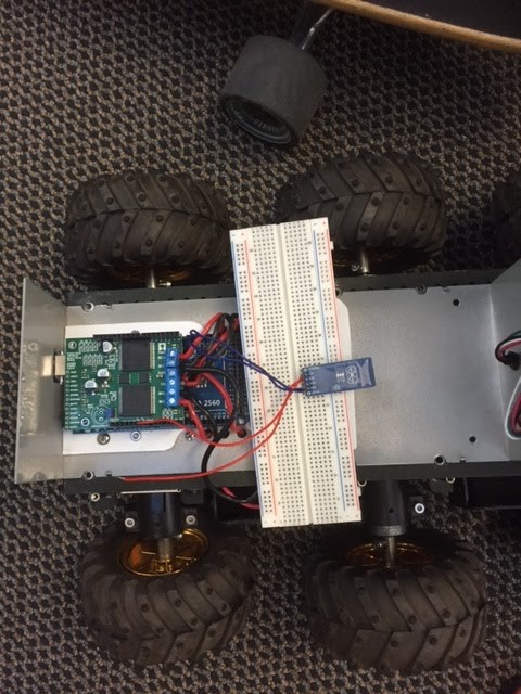
Changing just bits and pieces of the code, we were able to make the rover go forward, backwards, and turn. The java code that was changed was only the button name. The main change that made our rover move was changing the Arduino code. We sent the data to the motors instead of LED.
Making the LED App Control Motors:
The main thing that we changed in this code was the serial port, and adding the motor shield code. We changed the serial port that we use to send data to the Arduino. Since we are using the Arduino Mega, we use serial port 2 instead of pins 10 and 11 as above. In the first LED case, we made the rover go forward. The second LED made our rover turn right and the third LED made it go in reverse. On the Java code side, we didn’t change anything from the code, we just changed names of LED1, LED2, and LED3 to forward and reverse.
The demo video can be found here
Moving Rover Arduino Code:
The the code highlighted below is what was changed from the code given in the link above. These code were added so we can move the motors of our pathfinder.
#include <SoftwareSerial.h>
#include <stdio.h>
#include <DualVNH5019MotorShield.h>
DualVNH5019MotorShield md;
int ledONE = 2;
int ledTWO = 9;
int ledTHREE = 4;
int bluetoothTX = 11 ;
int bluetoothRX = 10 ;
char receivedValue ;
SoftwareSerial bluetooth ( bluetoothTX, bluetoothRX );
void setup()
{
Serial2.begin(9600);
Serial2.println(“console> “);
pinMode(ledONE, OUTPUT);
pinMode(ledTWO, OUTPUT);
pinMode(ledTHREE, OUTPUT);
// bluetooth.begin(115200);
// bluetooth.print(“$$$”);
// delay(100);
// bluetooth.println(“U,9600,N”);
// bluetooth.begin(9600);
}
void loop()
{
int brightness = 0;
int led = 0;
signed int data = 0;
//if( bluetooth.available() )
if (Serial2.available())
{
//data = (int) bluetooth.read();
data=(int) Serial2.read();
Serial2.println( data ); // for debugging, show received data
if(data == 26)
{
allDown() ;
}else if(data == 89)
{
allUp() ;
}else{
led = data / 100; // which led to select ?
brightness = data % 100 ; // 0 – 25 , LED brightness ( * 10 ) for actual value
switch(led) // Now, let’s select the right led.
{
case 0 : setLEDthree ( brightness * 10 ); break;
case 1 : setLEDone ( brightness * 10 ); break;
case 2 : setLEDtwo ( brightness * 10 ); break;
default : setLEDthree ( brightness * 10 ); break; // DO NOT know what to do ? must be led 3
}
}
//bluetooth.flush(); // IMPORTANT clean bluetooth stream, flush stuck data
}
}
// SHUT DOWN all leds
void allDown()
{
digitalWrite(ledONE, LOW ) ;
digitalWrite(ledTWO, LOW ) ;
digitalWrite(ledTHREE, LOW ) ;
}
// ALL up now
void allUp()
{
digitalWrite(ledONE, HIGH) ;
digitalWrite(ledTWO, HIGH ) ;
digitalWrite(ledTHREE, HIGH ) ;
}
void setLEDone(int brighteness) // move rover foward
{
int m1Speed = brighteness; // left motor
int m2Speed = brighteness ;// right motor
md.setSpeeds(m1Speed, m2Speed);
//analogWrite(ledONE, brighteness*16 ) ;
}
void setLEDtwo(int brighteness) // turn rover to the right
{
int m1Speed = brighteness; // left motor
int m2Speed = -brighteness ;// right motor
md.setSpeeds(m1Speed, m2Speed);
//analogWrite(ledTWO, brighteness*16 ) ;
}
void setLEDthree(int brighteness) // move rover in reverse
{
int m1Speed = -brighteness; // left motor
int m2Speed = -brighteness ;// right motor
md.setSpeeds(m1Speed, m2Speed);
//analogWrite(ledTHREE, brighteness*16 ) ;
}
Conclusion:
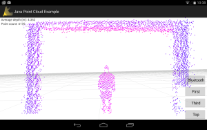
In conclusion, we were able to send data to the Arduino from Android OS via bluetooth. We then tried to control the our motors by changing up the code to light up LEDs to control the left and right motors on the pathfinder. The next step is to implement this code to the Google tango point cloud app and see if we can extract the depth and send it to the Arduino.
Source Materials:
- Sample code: https://github.com/hishriTaha/AndroidLEDcontrol
- Demo video: https://www.youtube.com/watch?v=G-8PoH8V9-Q
- Image: http://payload71.cargocollective.com/1/7/248583/3734433/amarino_905.png


