Sabina Subedi – Project Manager
Adan Rodriguez – Mission, Systems and Test
Jose Alcantar – Electronics and Controls
Nicholas Lukin – Design and Manufacturing
Review of Literature
By Sabina Subedi, Project Manager
Level 1 requirements for the Pathfinder from Spring 2016 were reviewed and analyzed per the requirement evaluation rubric provided below.
Requirement Evaluation Rubric:
- Is the requirement, Quantitative, Verifiable, and Realizable?
- Is the requirement located at the correct level (1 – Program/Project, 2 – System/Subsystem)
- Is the requirement response to a higher level requirement or customer’s objective (Requirement Flow Down)? Is the linkage clearly defined?
- Does requirement provide links to source material?
- Does the requirement move the design process forward?
- Are equations used to calculate a requirement provided and are answers correct?
- Is language in the form of a requirement?

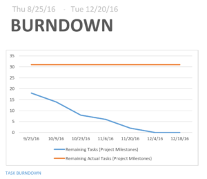
Figure 1: Review of requirements from Spring 2016
Program Objectives / Mission Profile
By Sabina Subedi, Project Manager
Program Objective Statement
The Pathfinder is an autonomous rover that is self-sufficient using solar panels. The design of the Pathfinder is inspired by the twin Mars rovers “Spirit and Opportunity.” The Pathfinder will utilize navigation waypoints on Arxterra control panel to traverse through the defined course, articulating ultrasonic range finders and LiDar sensor for obstacle avoidance. Digital slip differential will be implemented for unmanned turning of the rover during it’s course. In order to save battery, the Pathfinder will have sensors that will send signals to the motors to stop the wheels from spinning under no load conditions.
Mission Profile
The mission for the Pathfinder is to complete the same course defined for Spring 2016 AdBot. “The mission profile will be a test course consisting of the 9 steps in front of the USU building, then the concrete path clockwise leading down some inclines back to the bottom of the stairs.” (Spring 2016, AdBot Blogpost) The Pathfinder shall complete its mission in one evening. The pathfinder shall conduct its mission at night for better operation of the LiDar sensor.
Requirements
Program/Project (Level 1)
By Sabina Subedi, Project Manager
- The pathfinder shall be autonomous, demonstrating GPS navigation mode on Arxterra
- The pathfinder shall avoid obstacles articulating Ping Ultrasonic Range Finder and a LiDAR sensor
- The pathfinder shall implement digital slip differential for turning, i.e., inside wheels turn at a different speed than the outside wheels while turning
- The six wheels shall be on a rocker bogie suspension system to allow the Pathfinder to traverse through rough terrain and enable mobility
- Each wheel shall have its own motor in order to be able to be controlled independently
- Wheels under no load condition shall stop spinning in order to conserve power
- The physical design of the Pathfinder shall mimic the Spirit and Opportunity rovers.
- The pan and tilt system shall be modified to support an Android phone
- The pan and tilt system shall be sealed in order to protect it from weather conditions in December
- The Pathfinder shall explore the course defined by the AdBot rover. The mission shall be completed in 4 hours in the evening.
- The Pathfinder shall be completed by the last day of 400D course, December 154h, 2016
System/Subsystem (Level 2)
By Jose Alcantar, Electronics and Controls Engineer
- The Pathfinder shall use an Arduino Leonardo implementing the latest version of the 3DoT library. Due to customer request, the current Arduino Mega will be replaced with the Arduino Leonardo. The Leonardo will be programmed using the 3DoT library.
- The Pathfinder shall use GPS coordinates from its sensors to communicate position with the Arxterra app. This will allow GPS navigation and the use of waypoint navigation.
- For obstacle avoidance, a LIDAR sensor and two SeedStudio ultrasonic range finders (SEN136B5B) shall be implemented onto the design of the Pathfinder. The ultrasonic range finder will be able to detect the range of obstacles in front of the pathfinder from 3cm to 400 cm. The LiDAR sensor will be able to detect the obstacle itself, allowing the rover to maneuver around that obstacle. A trade off study was done prior to choosing this specific model of ultrasonic range finder.
- The design of the pathfinder shall resemble the Spirit and Opportunity rovers. The Spirit and Opportunity rovers are each 1.5 meters high, 2.3 meters wide and 1.6 meters long, and weigh about 400 lbs.
- Due to the removal of the Google Tango, the pan, and tilt platform shall be redone to accommodate solely an Android phone, specifically a Samsung Galaxy S7 Edge. The dimensions of the phone to be used are 9 x 72.6 x 7.7 mm (5.94 x 2.86 x 0.30 in). The phone weighs 157.6 g.
- The encasement for the Android phone shall be sealed to protect the device from outdoor conditions.
- This requirement will vary depending on the weather conditions on the day of the final demonstration in December. The forecasted load for the day of the final, December 15th, 2016, is partially cloudy with a high of 65 degrees Fahrenheit and a low of 47 degrees Fahrenheit. No rain is forecasted for that week. Historical average for the day is 67 °/47 °.
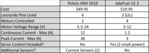
- In order for the Pathfinder to implement electronic slip differential 6-wheel drive, three separate VNH 5019 motor shields shall be used to allow the control of each independent DC motor. Testing will be done to find a suitable voltage ratio between the wheels to ensure slip differential turning.
- The ACS712 (SEN-08883) current sensor shall be implemented to get feedback on the amount of current passing through the load. This current sensor will allows us to measure load up to 5A of AC or DC current.
Source Material
The links below consist of sources that were used in developing the Level 2 requirements.
PINGER and Arduino:
https://www.arduino.cc/en/Tutorial/Ping
Ultrasonic range finder (SEN135B5B) Fritzing diagram:
http://fritzing.org/media/fritzing-repo/projects/3/3pi-robot-atmega-328p-and-ultra-sonic-range-measur/other_files/ULTRASONIC%20SEN136B5B.pdf
SeedStudio UltraSonic range finder and Arduino interface:
https://www.youtube.com/watch?v=y8ox5NPvcPc
SeedStudio Ultra-sonic range finder:
http://www.eio.com/p-40804-seeedstudio-sen136b5b-ultra-sonic-range-measurement-module.aspx
Ultrasonic Field of View test, Fall 2015 Pathfinder:
http://arxterra.com/pathfinder-ultrasonic-field-of-view-test/
Specifications of the Spirit and Opportunity:
http://hobbiton.thisside.net/rovermanual/
Waypoint navigation on Arxterra:
https://www.arxterra.com/arxterra-now-supports-waypoint-navigation/
Performance of Arduino Leonardo:
https://www.arduino.cc/en/Main/ArduinoBoardLeonardo
Performance of LiDar Lite V2:
https://www.sparkfun.com/products/retired/13680
Weather Forecast for December 2016:
http://www.accuweather.com/en/us/los-angeles-ca/90012/daily-weather-forecast/347625?day=86
Spring 2016 AdBot Preliminary Design Documentation:
http://arxterra.com/preliminary-2/
Low Current Sensor:
https://www.sparkfun.com/products/8883
Preliminary Budget
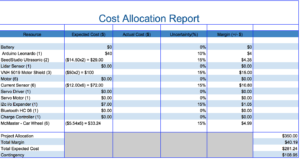
The preliminary budget was created based on the new upgrades required to the existing rover in order to meet the new Level 1 and Level 2 requirements for this semester, Fall 2016. This budget will be verified by our customer before any parts are purchased. Therefore, the total estimated cost is subject to change.

Figure 2: Preliminary Budget for the Pathfinder, Fall 2016
Design Innovation
By Sabina Subedi, Project Manager
A brainstorming exercise was performed in order to come up with creative solutions to the problems found in the existing Pathfinder. Some of the problems with the existing Pathfinder were:
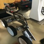
- It cannot climb up the stairs. This problem occured because the weight on the existing rover is not distributed properly. It could be fixed by lowering the center of gravity. Possible ways of lowering the center of gravity include but are not limited to redistributing the weight on top of the chassis, or lowering the entire platform and pushing the wheels further back.
- The rover draws excess current merely due to its weight. The weight could be reduced by milling excess metal off or by using lighter components. This could potentially increase the battery life.
- The existing pan and tilt system is designed for a Google Tango and is controlled by two servo motors. The existing encasement a bulky design made out of plastic. The bulkiness of the design limits the Pathfinder in its range of movement and makes it harder to navigate. Possible solution to this problem is to design a new pan and tilt system to hold an Android phone and utilize stepper motors instead of servos to reduce bulkiness as well as increase functionality.
Systems/Subsystem Design
By Jose Alcantar, Mission Systems and Test Engineer
Product Breakdown Structure
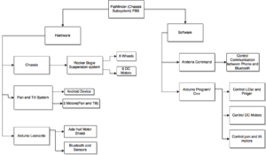
Figure 3: Product Breakdown Structure
The product breakdown structure demonstrates the hierarchical breakdown of the products that will be used in the overall design of the Pathfinder chassis subsystem. At the highest level, the Pathfinder chassis subsystem splits into two separate main subcategories, the hardware and software aspect. The hardware consists of three subcategory items, the chassis, pan and tilt platform, and the Arduino microcontroller. The chassis subcategory was organized by first starting at the bottommost level, where the manufacturing engineer is responsible. This consists of the six wheels and six DC motors that will be installed onto the rocker bogie suspension system and ultimately onto the chassis. The pan and tilt platform is the responsibility of the manufacturing and electronics engineer. At the lowest level, the category consists of the Android device, motors for pan and tilt, and the two sensors. These bottom level components will be installed onto the manufactured pan and tilt platform allowing obstacle detection and platform control. The Arduino subcategory is the physical microcontroller used on the pathfinder. This category is further split into two categories, the motor shield, and Bluetooth module. The electronics engineer is responsible for these components. The use of the motor shields allow for DC motor control and the Bluetooth module allows for communication between Arduino and Android.
The other main subcategory is the software block. This block is then further split into other functions needed for the control of the pathfinder. The first sub component is the software-implemented control of the pan and tilt motors. The second component is the software controlled DC motors used for the wheels of the pathfinder. Third is the control of the LIDAR and Pinger sensors used for obstacle avoidance. The fourth component is the software integration for communication between Android and the Bluetooth.
Electronic System Design
By Adan Rodriguez and Jose Alcantar
System Block Diagram
By Adan Rodriguez, Mission, Systems and Test Engineer
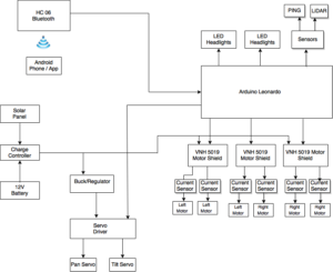
Figure 4: System Block Diagram
Interface Definitions
By: Jose Alcantar, Electronics and Controls Engineer
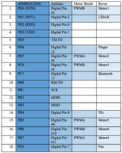
Figure 5: Interface Matrix
The interface matrix for the Pathfinder chassis subsystem tabularizes the pin connection layout of the electronic system. The embedded system is comprised of the ATMEGA32U4, Arduino Leonardo board, Motor Shield and finally sensors and actuators on the rover. The Arduino and motor shield use up some pins from the ATMEGA and in exchange get an extension in capabilities for the components used on the rover.
Fritzing Diagram
By: Jose Alcantar, Electronics and Controls Engineer
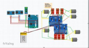
Figure 6: Fritzing Diagram
Source Material
The following sources were used in developing the interface definition.
https://cdn.sparkfun.com/datasheets/Sensors/Proximity/lidarlite2DS.pdf
https://www.arduino.cc/en/uploads/Main/arduino-leonardo-schematic_3b.pdf
https://www.arduino.cc/en/Main/ArduinoBoardLeonardo
https://www.adafruit.com/product/1438
https://cdn-shop.adafruit.com/datasheets/TB6612FNG_datasheet_en_20121101.pdf
Mechanical Design
By Nicholas Lukin, Design and Manufacturing Engineer
Overall Design
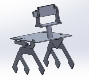
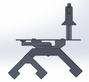
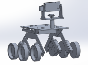
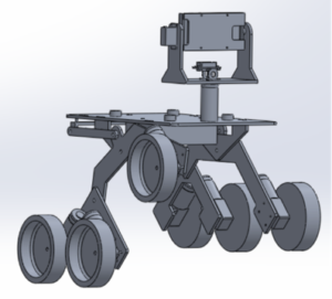
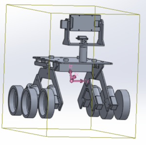
Figure 7 : Overall design of the new chassis
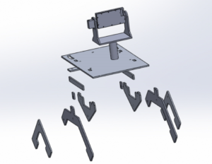
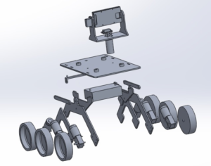
Figure 8: Exploded view of the new chassis
The above pictures are models of what the Pathfinder should look like in order to satisfy the level 1 and 2 requirements. In order to satisfy the mission objective of traversing the same course/path that was outlined for the “Spring 2016 Adbot” the Pathfinder will utilize a rocker bogie suspension system that is very similar to the design used on the Spirit mars rover. This suspension system gives the Pathfinder a wide and long stance allowing it to climb up and around obstacles such as rocks and stairs. The length from the front to the back wheel will need to be longer than the length of the base platform in order to produce a wide stance. This wide stance will prevent the Pathfinder from tipping backwards when going up steep surfaces. Many components will be mounted to the base platform such as the pan/tilt mobile case, solar panels, electronics box, battery and sensors. These components will be mounted in a way that will create even weight distribution on the base platform. This even weight distribution will also help the Pathfinder remain upright when going up steep surfaces. Using a rocker bogie suspension system and having even weight distribution will help achieve the goal of traversing the course.
Chassis Lightening

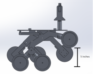
Figure 9: Rocker-Bogie Suspension system
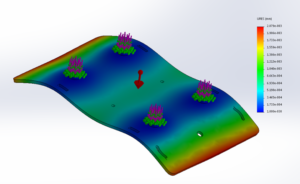
In order to conserve battery life and limit the stress put on the driver motors the chassis will be made as light as possible. The suspension components of the current Pathfinder will need to modified in order to achieve this requirement. The above picture shows the suspension components and how they may look in order to achieve the lightest possible design. About half an inch may be cut off from the inside of the suspension legs. Stress simulations and calculations will need to be performed to ensure that the new lightened chassis can handle the load of all the components that will be mounted to the base platform.
Mobile Phone Pan and Tilt System Design
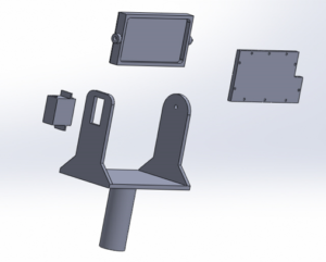
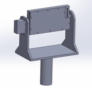
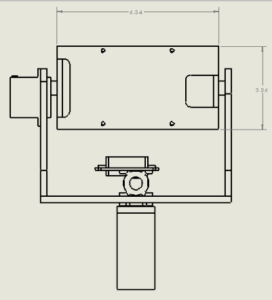
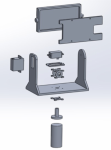
Figure 10: Pan and Tilt System design
The use of a Pan/Tilt mobile encasement is required in order to help the Pathfinder navigate through the course. The holder can be designed for an Android or Iphone. The above picture shows a proposed design model for an Iphone 6. Measurements were taken from an Iphone six and these exact measurements were used in the above model. The Pan/Tilt system will be driven by servos that will be mounted directly to the Pan/Tilt chassis. The above model does not include the servo that controls the “pan” movement. Future design will include the second servo. Wiring for the servo motors will be run through the support tube and then ran to the electrical box via the bottom side of the base platform.
New Wheels
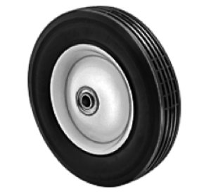
Figure 11: New wheels, McMaster-Carr 6″
In order for the Pathfinder to complete the course it will need to be equipped with new wheels. These wheels will have to be strong enough to support the load of the entire pathfinder and rugged enough to withstand the environment that the course will provide. The picture above is of a wheel sold by McMaster-Carr that may be used on the Pathfinder. The wheel is 6 inches in diameter and 1.5 inches wide. The axel has a diameter of 0.5 inches. The wheel hub is made of smooth steel and the actual wheel is made of solid rubber with hollow treads. The capacity of each wheel is 55 lbs. The wheel hub has ball bearings pressed into it to ensure smooth operation. Having a 6 inch diameter will allow the Pathfinder to get up stairs easier. Having a steel wheel hub may be too heavy therefore an aluminum wheel hub may be used instead. A wheel mounting hub will be designed in the future. This hub will properly connect the DC motor to the wheel. A link to the wheel specs can be found in the source material section.
Electrical, Wiring, AC Unit
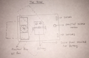
Figure 12: Electrical box and top view of the chassis
It is necessary that all electronics be protected during the mission. An electrical box will be used to house all of the electronics such as the micro-controller and motor driver shields. The electrical box may be made out of metal or plastic and will be mounted in the best place possible to ensure even weight distribution. A cooling fan might be used in case the heat produced by the electronics gets too high. This fan will be built into the electrical box along with vents to ensure proper air flow. Future tests will need to be run with the electronics engineer to see how hot the electronics get. All wiring will be neatly mounted and covered for protection. The battery is the heaviest part of the electric system and will need to be mounted in the center of the base platform in order to maintain even weight distribution. The picture above shows a general idea of where the electronics will be mounted on the base platform relative to everything else.
Solar Panel Interconnection
The design of the actual solar panel support is not in our scope of work but it is necessary for us to know how it will look in order for us to figure out how it will be attached to the chassis. It is crucial that the solar panels have good weight distribution and that they are mounted on the base platform in the correct location. Working with the Solar Panel Group in the future will be necessary in order to figure out what the best location is.
Source Material
Spirit Rover:
https://en.wikipedia.org/wiki/Spirit_(rover)
Wheels:
http://www.mcmaster.com/#2331t11/=149w7jd
General Information on spring 2016 Pathfinder:
http://arxterra.com/spring-2016-pathfinder-preliminary-design-documentation/
Design and Unique Task Description
The following tests and experiments shall be conducted.
Solidworks simulations will need to be performed in order to figure out if the new lighter chassis is strong enough and to see if the center of mass is in the appropriate location. These tests include load and shear analysis (stress test) and various animations
Rolling tests will need to be performed on the new wheel to make sure they do not wobble and have a smooth rotation.
Pan/tilt platform may be animated to show proper mobility.
Weight distribution test with solar panel connected.

