Solar Cell Current Sensing
By Edgardo Villalobos
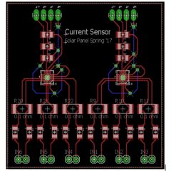
Custom PCB created by combining two INA3221 into one board.
Table of Contents
INA3221
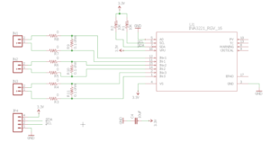
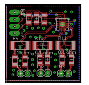
Original Eagle CAD
Custom PCB with 2 INA3221
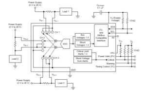
Three INA219 = One INA3221
Description
The INA3221 is a three-channel, high-side current and bus voltage monitor. It contains the setup of 3 INA219 single-channel, high-side current and bus voltage monitor.
Setup
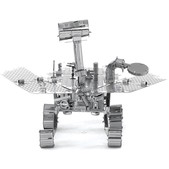
The solar panel on the pathfinder rover contains 6 different panels with 6 solar cells on each panel that are setup in a certain way in series and parallel to get an output of 18 volts and 200 milliAmp from each of the panels to get a total of 18 volts and 1 amps. To test the current flowing through each of the 36 cells, we are going to use the INA3221 current sensor. As described in the INA3221 datasheet, this sensor senses current on buses that can vary from 0V to 26V. Because the INA3221 is three channels, it only measures the current running through 3 inputs, meaning we’ll need 2 per panel. The original Eagle CAD PCB layout was modified in order to get a total of six inputs that will match up perfectly with the 6 cells on each panel, meaning we will only need 6 boards as opposed to 12.
Since the these sensors can only have 4 addresses, I2C multiplexers are required.
Parameters
References
http://www.ti.com/product/INA3221/description
http://www.ti.com/lit/ds/symlink/ina3221.pdf
http://www.ti.com/lit/ds/symlink/ina219.pdf
http://www.switchdoc.com/wp-content/uploads/2015/04/INA3221BOB-042015-V1.0.pdf
Eagle CAD Files
https://drive.google.com/drive/folders/0B4jU8uMDmOoiU1dOM0tzSU1qeHM
- Custom Eagle CAD Schematic: Current_Sensors.sch
- Custom Eagle CAD PCB : Current_Sensors.brd
- Original Eagle CAD Schematic : ina.sch
- Original Eagle CAD PCB : ina.brd
- INA3221 Eagle CAD Library : ina.lbr

