Pathfinder Final Blog Post – Spring 2018

By: Jordan Smallwood (PM)

Approved By: Miguel Garcia (Quality Assurance)


Pathfinder Team:

Jordan Smallwood (PM)

Diane Kim (E&C)

Mohamad Yakoub (MST)

Adolfo Jimenez (Manufacturing)

Table of Contents

Executive Summary:

By: Jordan Smallwood (PM)

Mission Objective:

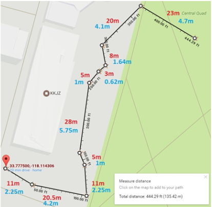
Figure 1: Final Course Outline

The Spring of 2018 Pathfinder will follow the path laid down by previous Pathfinders. The mission will begin in front of the CSULB library where the rover will exit its cocoon state. The rover will then proceed to begin its journey through campus, a 0.09 mile journey to its charging station. There will be 10 predefined GPS checkpoints along the way and the rover will traverse a flight of stairs. Once the rover has arrived at the charging station it will begin to track the sun and provide the Arxterra user with up to date battery level conditions. Specifically the Pathfinder will demonstrate the following:

  • Custom solar panels capable of tracking the sun and exhibiting optimum orientation so that battery charge takes the least amount of time.
  • The rover will be able to enter and exit a cocoon state. The term cocoon state implies that the solar panes will fold up so that in the event of a dust storm the solar panels will not become damaged. This state will be entered if the rover is in launch, a dust storm or whenever the rover is operating over steep terrain.
  • The rover will be able to communicate with the Arxterra app providing information like battery level, panel angles, panel voltages and charging current.
  • The solar panels will have a form factor identical to those of the Spirit and Opportunity Mars Rovers.
  • The rover will exhibit a 6-wheel slip differential for turning and traversing rough terrain. Since the robot will be climbing over random objects, some wheels will not require the same speed as other wheels and this needs to be considered while operating the rover.
  • Demonstration of GPS navigation with obstacle avoidance.
  • The course mapped out by F’16 and S’17 will be the same course for S’18.
  • There shall be no modification to the rover that stands in the way of high desert operation.

Project Requirements:

By: Jordan Smallwood (PM)

Level 1 Requirements:

  1. The pathfinder shall travel a 0.09 mile course. This course includes going up a set of 3 stairs at a 45 degree incline and another set of 3 stairs with a decline of 45 degrees.
  2. Pathfinder should launch from a cocoon state
  3. The Pathfinder should enter and exit the cocoon state by Arxterra app user input.
  4. Pathfinder shall allow the user to enter the “articulate state” program module which should be available once the Pathfinder has exited its cocoon state. This sequence should direct the solar cells at the proper orientation to allow max charge of the battery.
  5. The Pathfinder shall update the user with information about GPS location, battery level and charge current when in the “Articulate state”. The Pathfinder should update the user with panel angles.
  6. The overall solar panel system will be a scale model of the Spirit and Opportunity Mars and Rovers.
  7. No design decision shall preclude operations in a high desert environment. (Amboy, California)
  8. The Pathfinder will use high-side detection and correction. Consequently, wheels under a no-load condition shall be considered and power to that motor shall be decreased.
  9. A 6-wheel electronic slip differential shall be implemented.
  10. The Pathfinder should demonstrate obstacle avoidance while making its journey through campus using the ultrasonic sensors.
  11. Rocker bogie mechanism shall be improved by implementing and operationally verifying a differential gear-box system as opposed to the differential bar.
  12. The Pathfinder shall be designed for easy assembly and disassembly.

Level 2 Requirements:

1.1: The power budget and battery will meet the requirement of the determined course. The actual distance traveled shall be used to verify the requirement.

1.2: In order to travel up these stairs our mass report along with our motor mock up shall verify that this can be accomplished.

2.1: To perform the cocoon state function the solar panels will be mounted to worm gears attached to DC stepper motors to ensure smooth operation.

3.1: The Pathfinder should communicate via Bluetooth with the Arxterra user and should have an interface allowing the user to enter/exit the cocoon state.

4.1: The articulate state module should adjust the positions of the solar cells using a proportional controller.

4.2: The proportional controller should accept the charge rate as an input and should output changes in orientation.

5.1: While communicating with the user via Bluetooth on the Arxterra app the Pathfinder shall respond with packets of information related to this information

6.1: The side and rear panels shall be capable of position orientation to enter and exit the cocoon state and also optimize battery charge.

6.2: The solar panels should enter the cocoon state when the Pathfinder falls.

7.1: These panels will be constructed of aluminum such that the rover can operate in the harsh desert conditions typical of Mars.

8.1: A software program shall be used ensuring that the wheels are spinning at the same rate.

8.2: Shaft/Rotary encoders shall be used to determine the speed of the wheels

8.3: Current sensors shall be used to determine the load on the wheels

8.4: To conserve energy, the rover shall stop rotation of a freely moving wheel using the current sensors

10.1: The rover should not make any attempt to climb an object that it is unable to clear

11.1: The differential gear box will be constructed of three miter gears, three machined shafts, six mounted bearings and shaft collars.

11.2: This mechanism will be mounted on top of the Pathfinder and enclosed in an aluminum box.

12.1: The design of the aluminum box of the Pathfinder shall be designed for easy access to the electrical components.


System Design:

System Block Diagram:

By: Mohammad Yakoub (MST)

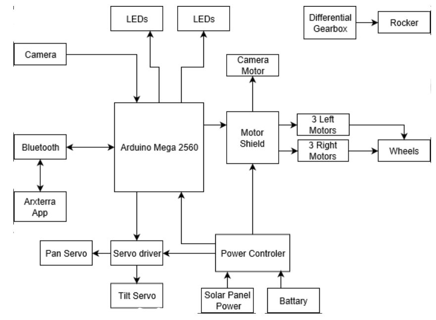
Figure 2: System Block Diagram for Pathfinder Project

The system block diagram describes the overall interconnections of all the peripheral systems. At the heart of the system you will find the Arduino Mega which controls virtually every device in the project. This is controlled via the Arxrobot app through bluetooth communication.


Work Breakdown Structure:

By: Jordan Smallwood (PM)

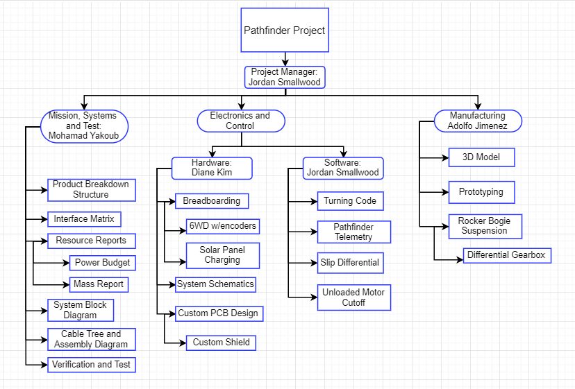
Figure 3: Work Breakdown Structure for Pathfinder Project

The work breakdown structure describes the major responsibilities of each engineer working on the project. The Electronics and Control division has been divided into two main categories, software and hardware. The Manufacturing division was primarily responsible for the overall fabrication of the Pathfinder and detailed SolidWorks model. And finally the Mission, Systems and Test engineer is responsible for the integration of all these different divisions.


Product Breakdown Structure:

By: Mohammad Yakoub (MST)

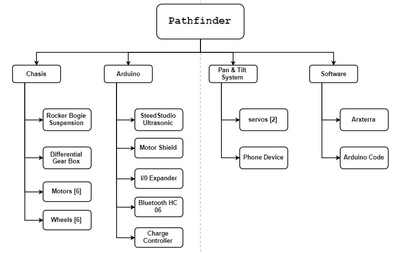
Figure 4: Product Breakdown Structure for Pathfinder Project


Resource Reports:

Final Power Report:

By: Mohammad Yakoub (MST)

Figure 5: Final Power Allocation Report

Power Report


Final Mass Report:

By: Mohammad Yakoub (MST)

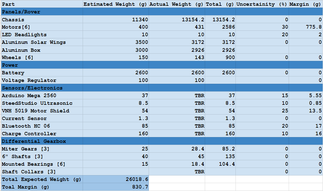
Figure 6: Final Mass Report

Mass Report


Final Cost Report:

By: Jordan Smallwood (PM)

The first cost report includes all purchases that were made by our team for our current project. It does not include cost of material that was purchased from previous semesters.

Final Cost Report

The second final cost report includes past purchases from previous semesters that were used in the making of our current design.

Final Cost Report 2


Interface Matrix:

By: Diane Kim (E&C)

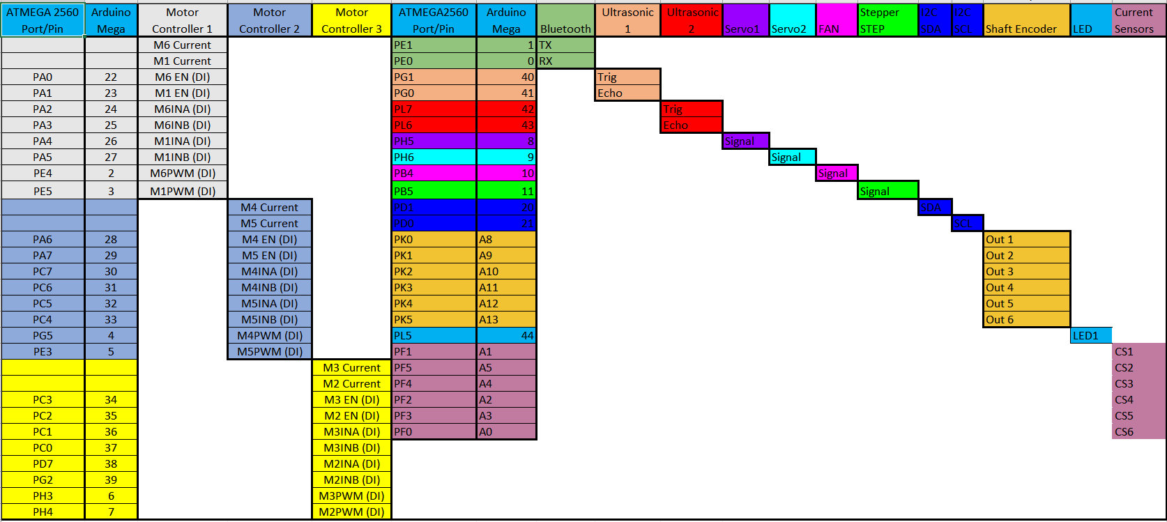
Figure 7: Interface Matrix describing pin location’s of system and peripherals

The interface matrix describes the various signal locations for the Pathfinder’s system diagram. Having a good description of where signals are coming in and out is extremely beneficial throughout the course of project design. Many times throughout the semester this document will be referred to and when coding this can often solve many problems.


Mission Command & Control:

By: Jordan Smallwood

The Pathfinder is connected to the Arxrobot app via Bluetooth communication. In addition, the Arxrobot app is connected to the Arxterra Control Panel to expand the capabilities of the Pathfinder. This method of controlling the phone that controls the rover is ideal for GPS navigation, telemetry, and video feedback without the need for including additional sensors and devices. More information regarding the interconnections is described here.


Software Design:

By: Jordan Smallwood (PM)

No-Load:

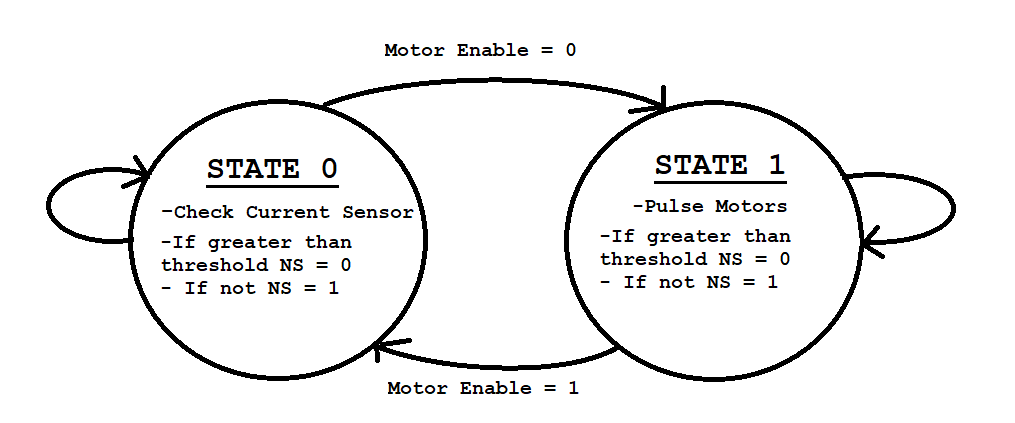
The Pathfinder has been equipped with 6 high-side current sensors capable of detecting current draw up to 5A to each motor. While these sensors are only calibrated for the motors spinning in one direction a level shifter can be implemented such that we can detect up to 2.5A in both directions. These sensors are used to detect whether or not a load is present on the motors. The difficult task is knowing when to turn the motors back on. To do so we had to implement a pulse motor routine that would turn the motors on for a moment and check the current. This was all done with software by inserting a 2-state FSM in a timer interrupt.

Figure 8: No Load FSM

One of the major issues with this technique is that whenever you turn on a motor from an off state the current required to move the shaft is much greater than normal operation. Therefore you have to wait a moment until you can measure the current to allow the motor to stabilize. This technique has been accomplished and more information regarding this concept can be found here.


6 Wheel Electronic Differential:

A six-wheel differential was implemented in software and hardware with the use of pin change interrupts and quadrature hall effect sensors. While pin change interrupts are more tedious to manage, they offer a significant bonus as virtually every pin can be configured to operate in this manner. The Pathfinder will be completing turns as well as traveling over random objects and this is vital to move forward and avoid unnecessary drag on the other wheels. The process involves 6 unique controllers that track a set pulse delay. More information regarding the 6 wheel differential can be found here. And here.


GPS Navigation:

Due to time constraints and non-software related issues, the Pathfinder is currently unable to perform GPS navigation. However, access to GPS information regarding latitude, longitude and heading can be extracted from the Arxrobot application onto the Arduino. Furthermore, these values can be modified to produce distance to checkpoints and required turn. Although this feature is currently not functional it is definitely feasible.


PCB/Hardware Design:

By: Diane Kim (E&C)

Chassis PCB:

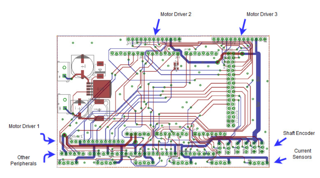
Figure 9: Layout of Final Chassis PCB

The final chassis PCB makes the following connections:

  • Motor Drivers (3)
  • Motor Current Sensors (6)
  • Shaft Encoders (6)
  • Ultrasonic Sensors (2)
  • HM-10 Bluetooth
  • LEDs (2)
  • Servos (2)
  • Fan
  • Stepper Motor Driver STEP
  • I2C connection (SDA and SCL)
  • LM2596 Buck Converter

For more information regarding the final chassis PCB please visit this link.


Solar Panel PCB:

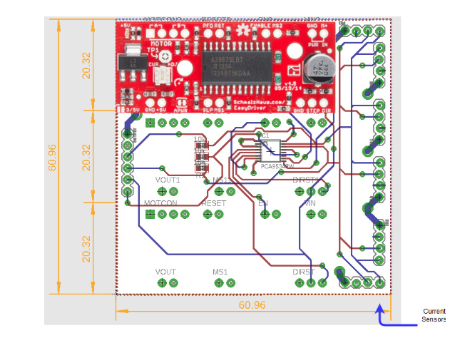
Figure 10: Layout of Custom Solar Panel PCB

The solar panel PCB contains the following systems:

  • Current Sensors (6)
  • Stepper Motors (3)
  • GPIO Expander

For more information regarding the solar panel PCB please visit this link


Final Mechanical Design:

By: Adolfo Jimenez (Manufacturing)

Chassis Design:

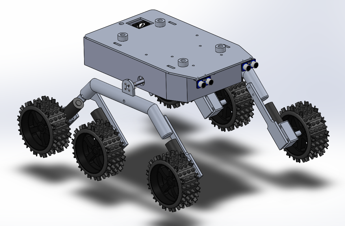
Figure 11: Final Design of Pathfinder

The final chassis design is similar in nature to previous semesters with the exception of a few major upgrades. The previous design had radial bearings on the rocker mechanism which was not properly installed. We have upgraded the design to include the use of thrust bearings since the load is axial.

In addition to the rocker bearings we have installed a gear-box differential to provide fluid motion transfer from one set of wheels to the other. The previous design involving a differential bar seemed to have many issues that were addressed in previous blog posts.

The new chassis also expands the total room for electronics tremendously. The size of the overall box is 14″ x 9″ x 3″. This is plenty of room for proper wiring and placement of electronics.

More information can be found here. ONCE FINAL DESIGN APPROVED NEED TO INCLUDE LINK


Final Solar Panel Design:

When it came time to design the new solar panels many different ideas presented themselves. We considered opening and closing the solar panels with the use of a winch/pulley system, however the customer did not approve. Ultimately we wend with a worm-gear with DC motor system. The issue with this design is that there is no support for the miter gear on the worm-gear.

For more information please visit this blog post.


Verification and Validation:

By: Mohammad Yakoub (MST)

Please refer to the link within the resources section for further information.


Pathfinder Improvements:

By: Jordan Smallwood (PM)

  • Rocker’s are free to rotate about the bogie mechanism with the installation of thrust bearings
  • Gearbox differential allows rocker-bogie mechanism to move the way it was intended.
  • Magnetic hall effect sensors on the motors allow for speed control
  • High side current sensors provide a means of determining load on a motor.
  • Enlarged electronics box provides shelter for delicate electronics that would otherwise be destroyed in a desert environment.
  • DC Fan with filter built into electronics box
  • Quick removal of lid for access to electronics
  • Power distribution system securely fastened to electronics box with in-line fuse
  • Wiring harnesses throughout for a clean design

Experiments Conducted:

  1. Solar Panel Charging
  2. Stepper Motor Study
  3. Motor Mock Up
  4. Solar Panel Trade-Off Study
  5. Buck Converter Efficiency
  6. Ultrasonic Field of View Test

Schedule:

By: Jordan Smallwood (PM)

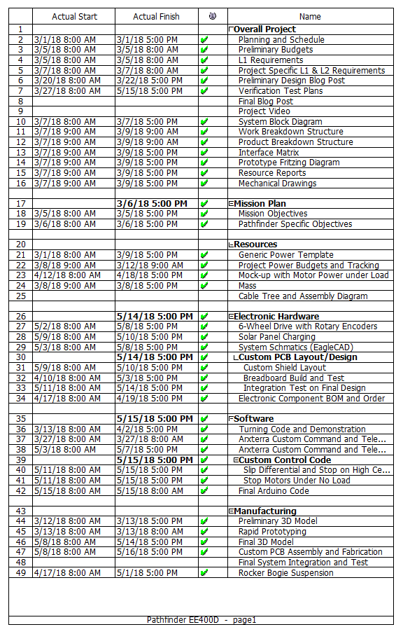
Figure 11: Schedule for Pathfinder Project

Burndown Chart:

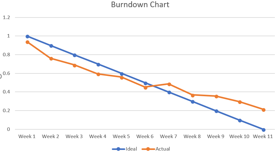
Figure 12: Burndown Chart for Pathfinder Project

The Pathfinder project was one of the largest in terms of what needed to be accomplished and size. Many modifications needed to be made to the Pathfinder before tests could be performed to determine whether or not we would meet our requirements. Towards the end it became more and more difficult to get things done due to the complexity of the remaining tasks which is why you see the slope of the ‘actual’ line going to zero. If you want your project to be successful it is paramount to get the robot up and moving before the semester’s break that way you’ll have plenty of time to make modifications in the last month or so.


Final Thoughts:

By: Jordan Smallwood (PM)

The Pathfinder project will have to wait until another semester to make it’s course through campus going up stairs and following commands from the Arxrobot App. Due to some very unfortunate design flaws the PCB was destroyed and we did not have the time to regenerate a new one. Since the Pathfinder is made of aluminum it is very important to ensure that all electrical systems are insulated.

Our design flaw was without a doubt something you wouldn’t have anticipated. The concept was to mount the Arduino to the Pathfinder chassis to secure the electrical system to the body. What we didn’t realize was that by using metal bolts we grounded the entire chassis. When attaching the battery terminals to the switch, the positive lead was set down for a moment which allowed for a short to take place. Needless to say the PCB didn’t respond well to this high current.

A new PCB will be fabricated and the Arduino will be mounted with plastic to prevent any shorts from taking place.

In the end, the Pathfinder has seen some major upgrades and there is no doubt that this robot will be a great piece of equipment to showcase for the EE department. Future modifications that can be made are:

  • Upgrade the chassis to include housing for micro-sojourners
  • Redesign solar panel folding system
  • Chassis/Panels should be made of lighter material such as carbon fiber

Resources:

  1. PathfinderEagleFiles
  2. Resource Report
  3. Final Arduino Code
  4. Link to Google Drive
  5. Master Test Case
  6. Verification Matrix
  7. Atmel Datasheet
  8. Final Video

Final Arduino Code

By: Jordan Smallwood (Project Manager)

Approved By: Miguel Garcia (Quality Assurance)


Table of Contents

6-Wheel Differential:

The six-wheel differential takes advantage of pin-change interrupts since most of the external interrupt pins are lodged within communication pins on the ATMega 2560. The way it works can be viewed here. Currently we are experiencing difficulties getting the software to work, this may be due to the short that took place while wiring the Pathfinder up. I believe there may be some issues with the motor drivers and we will have to replace these. The code for a 6-wheel differential can be found here: Final Arduino Code.


No-Load:

In order to preserve energy in the wastelands of Mars, we need to cut off power to motors that are spinning freely. In order to determine if a wheel is spinning freely we compared the current power running to them with known values of no-load current and would turn them off if need be. Turning off the motors is not an issue but it’s determining when to turn them back on that poses a threat. We can pulse the motors to find out if a load is present but at that point it may be too late and will create unnecessary drag on the system. Further studies can be found here. If you would like to view the code it is included in the .zip folder mentioned in the previous section.


GPS Navigation:

Due to time constraints and non-software related issues, the Pathfinder is currently unable to perform GPS navigation. However, access to GPS information regarding latitude, longitude and heading can be extracted from the Arxrobot application onto the Arduino. Furthermore, these values can be modified to produce distance to checkpoints and required turn. Although this feature is currently not functional it is definitely feasible.


Conclusion

Acting as Project Manager/Software was an extremely difficult task this semester. I would have liked to focus on one specific area, specifically software, so that I could have done more as far as coding went. But will have to continue working on this code throughout the summer so that Pathfinder will be able to complete it’s mission.


References

  1. https://www.arxterra.com/pathfinder-arxterra-communication-part-two/
  2. Final Arduino Code

Final Pathfinder Design

Author: Adolfo Jimenez (Manufacturing Engineer)

Verified By: Jordan Smallwood (Project Manager)

Approved By: Miguel Garcia (Quality Assurance)


Table of Contents

Introduction:

Figure 1: Isometric View of the Pathfinder Robot

Many modifications were made to our original designs of the pathfinder rover. These designs were implemented to accommodate the requirements of the rover being able to operate in a dessert environment. Our preliminary design involved the use of an electronics box, similar to the one used by previous semesters to house all the electrical components required for the operation of the robot. The use of the box, combined with the considerable real estate taken up by both the battery and differential gear mechanism, required a redesign of the housing for all of our components.


Aluminum Body:

Figure 2: Isometric view of Rover body without top cover 

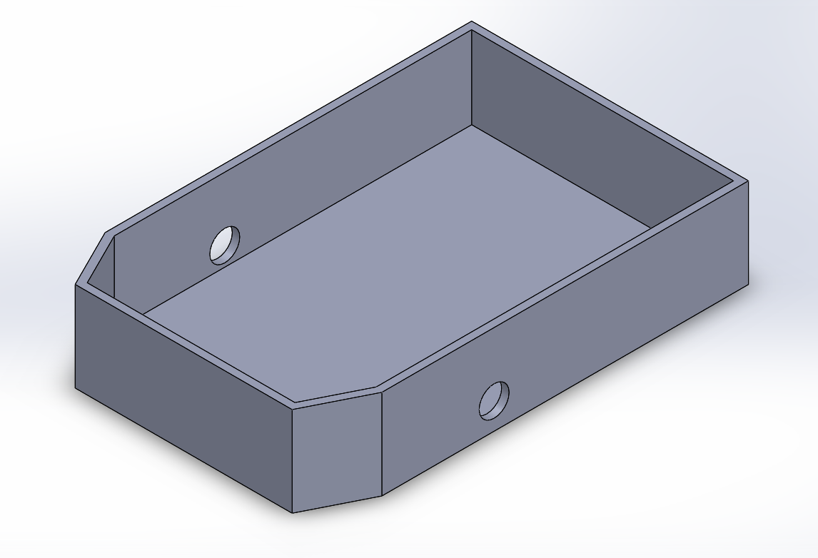
The main design update was the use of an entire aluminum body with dimensions 3” x 14.25” x 9.25” constructed from ¼” thick aluminum alloy 6061 that would be used to house not only the electrical components but the differential and battery as well.  This new aluminum housing required us to change the orientation of our differential from previously being mounted underneath the aluminum plate to above the base of the new aluminum body.


Mounting Hub:

Figure 3: Rocker-Bogie with Differential Gear System Re-oriented

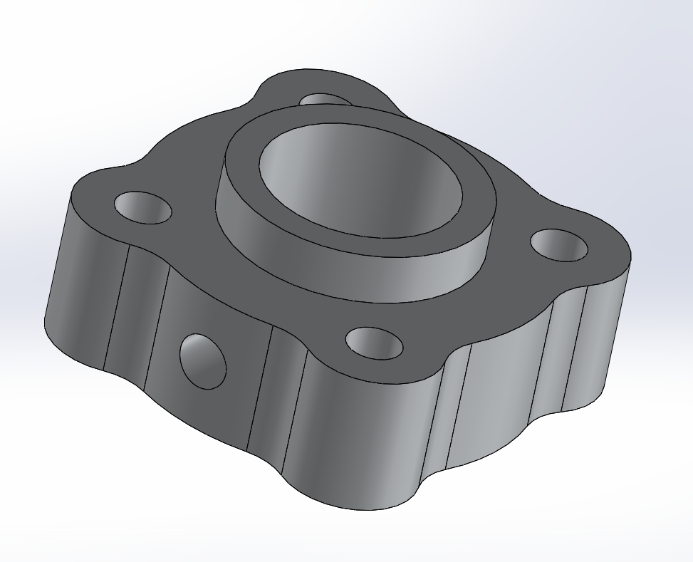
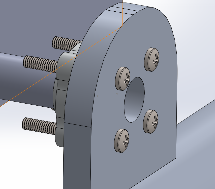
Our requirement to make the rover able to be disassembled forced us to find a solution other than welding to fix the differential axels to the wheel assemblies. The differential was mounted to the side arm assemblies (making up the rocker-bogie suspension system) using a 3/8” set screw hub purchased from SparkFun.

Figure 4: Set screw Hub (top); Screw Hub mounted to wheel assembly (bottom)


New Motors:

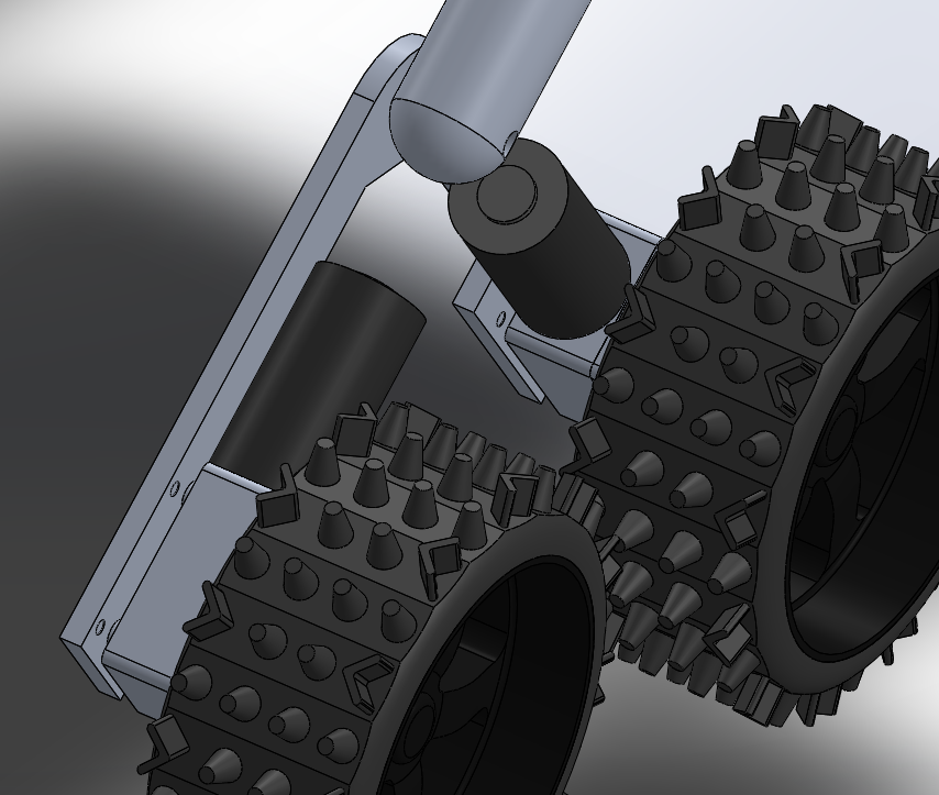
Our need to have encoders to be able to measure and vary the speed of our wheels to implement the slip differential required us to purchase new motors with included encoders. These new motors were slightly smaller than the ones used by previous semesters, required less current to operate and generated more torque. The only trade-off being that these new motors operated at a much slower RPM. Though the new motors themselves were different in size to that of the previous motors, fortunately for us, the gearbox on the new motors were the exact same size as the ones found on the old motors, allowing us to easily mount our new motors on the same motor mount used of the rover. In addition to the new motors, new thrust bearings were purchased to replace the previous radial bearings that were incorrectly acting as spacers on the bogie mechanism.

Figure 5: View of Rover Bogie with upgraded motors.


Internals:

Figure 6: Isometric and top-side views of robot internals

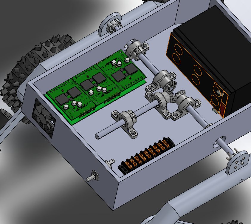
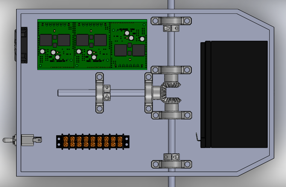
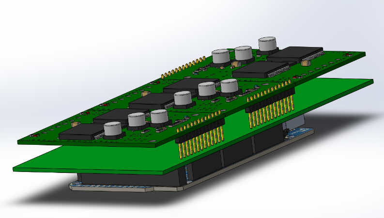
Inside the rover body can be found all the electrical components and wiring for the rover. Located at the very front of the robot is the 12-Volt rechargeable battery used to power the entire rover. At the very center is the differential mechanism requiring most of the real estate within the rover body. On the right side of the differential is the power distribution block, it is used to redistribute the power from the battery to the external motors as well as the rest of the internal electronics. On the left side of the differential can be found the custom PCB for our robot, connecting our 3 sets of paired motor drivers to an Arduino Mega.

Figure 7: Custom PCB connecting motor drivers to Arduino Mega

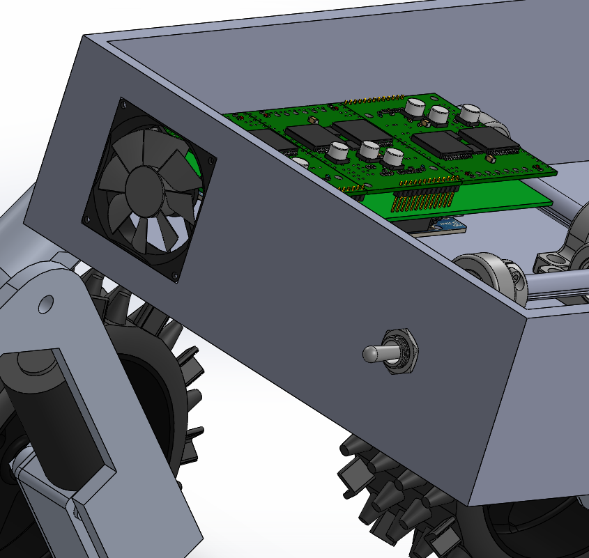
The heat generated by the motor drivers and the rest of the components was cooled down using a fan located to the rear of the rover, near the custom PCB. The need to keep eternal particles out of the rover had us opt for a fan with included filter. To the right of the fan, also on the rear, is a toggle switch which can be used to turn the robot on and off.

Figure 8: Rear view of rover showing fan and toggle switch


Sensors/Lid:

Figure 9: Top cover with Ultra-Sonic sensors

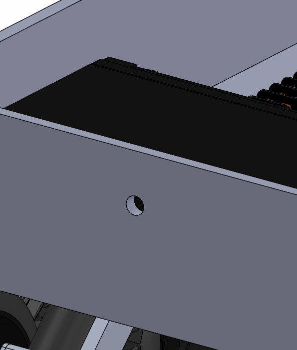
The aluminum panel making up most of the rover chassis for previous generations was repurposed to serve as a top cover. To do this, the triangular side assemblies that were once used to connect to the rocker-bogie suspension system were removed. The sensors and sensor mounting plates, however, were left intact. With all electrical components located inside a closed body, a method of getting the wiring to the outside sensors and LED’s required, to combat this, a small hole was drilled at the front of the rover body just wide enough to allow wiring through.

Figure 10: Hole at front of rover for sensor wiring


Conclusion:

The incasing of our components in an aluminum body ensures that our electrical components, as well as our differential system, will be more secure from the elements. The obvious danger in using a conductive material to enclose electrical components means add precaution when wiring everything up. Much to our dismay, accidental contact between the wiring and the rover body can lead to short circuits, in our case that meant the frying of some of our components. For future semesters, we recommend extreme caution when wiring components inside the rover.  A small layer of non-conductive material such as rubber could be used to combat this and help prevent accidental short-circuiting. Rubber could also be used to somehow cover holes such as those made for the differential axels and ultrasonic sensors to further prevent external particles from entering the robot. The reason for this being that large enough accumulation of particles between the differential might cause it to jam, or worse, conductive particles such as iron could also get into the components and cause short-circuiting.

References:

  1. Solidworks Files: https://drive.google.com/drive/folders/11zZJXZYqD2LwFxzG09dudBXihLIsBzNR
  2. Fall 2016 Semester design: https://www.arxterra.com/the-pathfinder-fall-2016/
  3. Custom PCB: https://www.arxterra.com/custom-chassis-pcb/
  4. Updated Bearings: https://www.arxterra.com/bear-ings/

PCB Fabrication

Author: Diane Kim (Division Manager of E&C Hardware)

Verified By: Jordan Smallwood (Project Manager)

Approved By: Miguel Garcia (Quality Assurance)


Table of Contents

Introduction

To fabricate our board, we use a PCB fabrication machine called the V-One from Voltera. Its function includes printing, soldering, and drilling.

Printing

V-One uses conductive ink to print the traces of the circuit. It will print the traces and bake it as well. The limits of the traces are:

  • Minimum 8 mil trace width and spacing
  • Minimum 0.65 mm pin pitch for SMT components
  • Minimum 0603 passive size
  • Minimum circuit size 1 x1 mm

Soldering

After the trace is done, the V-One can print the solder paste onto the desired traces. The user must manually place the pieces onto the board. After the pieces are place, the V-One will bake the board once more to heat up the solder paste. The limitations of soldering are:

  • Minimum 0.5 mm pin pitch for SMT components
  • Minimum 0402 passive size

Drilling

The V-One can also drill holes through the circuit board. The drill sizes are 0.7, 0.8, 0.9, 1.0, 1.6 mm for the diameter. Therefore, the smallest hole size is 0.7 mm which is 27.6 mil. To connect the top and bottom layer, rivets are used, and the given rivet sizes are 0.4 mm and 1.0 mm for the inside diameter.


Software

To communicate between Eagle CAD and the V-One, Gerber files are used. V-One has its own CAM processor that outputs the top, bottom, solder paste and drill layers. Once the Gerber files are converted from the Eagle CAD, it is uploaded into the Voltera software which allows the user to choose the desired action: print, solder, bake, or drill. Each process has its own procedure which the user can follow easily with the guidelines that are shown through the process on the right side of the window.


Procedure to Fabricate the Board

Drilling:

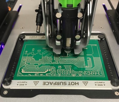
Drilling is done first. The board is placed onto the pad and then the drill size is chosen. For our board, we are using the 0.7 mm and the 1.6 mm drills.

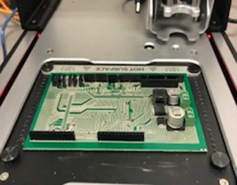
Figure 1. Picture of the drill in action

Printing:

After the drilling is done, the top layer is printed first. The board is not moved therefore the previous alignment can be used. After the conductive ink is printed, the board is heated to bake the conductive ink.

Figure 2: printing process

After the top layer is baked, the board is flipped to print the bottom layer. Since the board is moved, alignment is needed so that the top and bottom match. After the alignment is done the bottom layer is printed and baked.

Connecting Top and Bottom Layers:

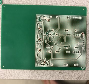
The top and bottom layer are connecting using the rivets. The flat side of the rivets are placed into the through-holes connecting the top and bottom. To flatten the non-flat side of the rivets, the rivets pressing tool is used. After each rivet is pressed, the multimeter was used to confirm that there is a connection between the top and bottom pads.

Figure 3: Rivets done

Cutting the Board

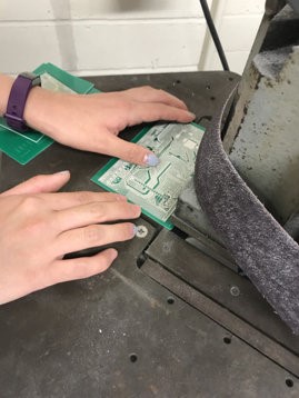
We needed to cut the board because the machine doesn’t have the function to do so. Therefore, we used the machines given access to mechanical engineering majors to do so.

Figure 4: Cutting the excess part of the board

Soldering:

Alignment is needed once again since the board is moved so that the location of the pads is known to the machine. The solder paste is printed on the pads and the components are placed onto the correct locations and baked once more.

Figure 5. Picture of the soldering

After the surface-mount component is placed, the through hole components. For our board, we had male and female connectors that needed to be hand soldered. Following the guide form the soldering workshop blog post, the connectors were hand soldered

Final Testing:

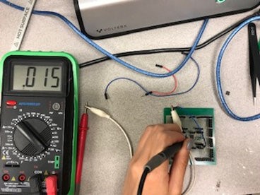
The final product is shown below and the connections were checked using a multimeter. Basing off the interface matrix, the connection between the peripheral systems pinout and the ATmega2560 pinout was checked. All the connections were checked.

Figure 6: Final Project

Figure 7. Testing the connection of the traces


Conclusion

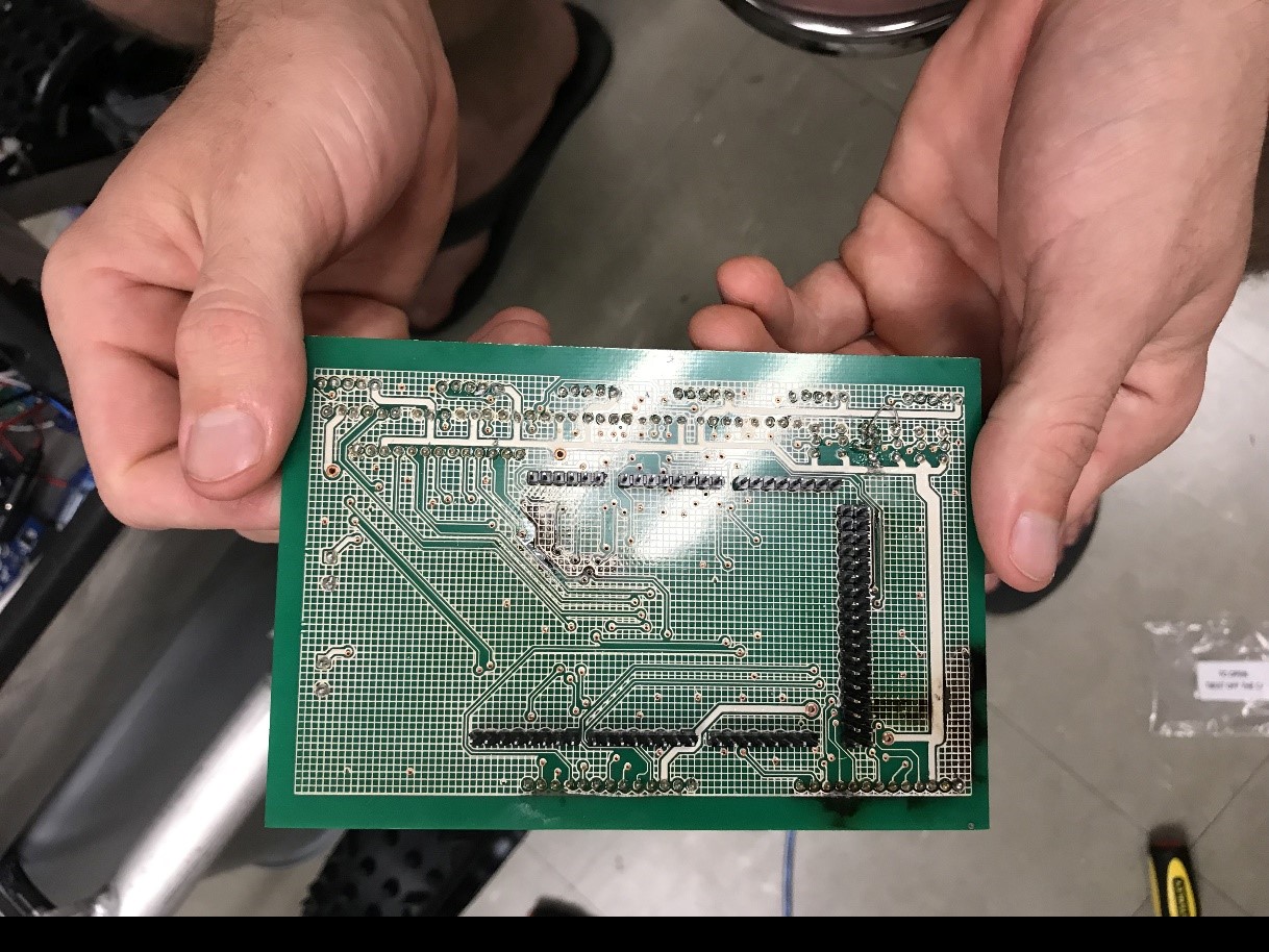
The time taken to fabricate the PCB was 7 hours. It took two hours to draw the traces for each side, one hour to bake the traces, and another hour to solder on everything. When it came to testing the board, we weren’t able to due to technical problems. We were able to connect all the components onto the circuit board and the ATmega256. However, during the process, the board got shorted and damaged the board. We didn’t have enough time nor material to print out the board, therefore, we weren’t able to print out another one.

Figure 8: Image of the damaged board

Solar Panel Charging

By: Mohammad Yakoub (Mission, Systems, and Testing)

Verified By: Jordan Smallwood (Project Manager)

Approved By: Miguel Garcia (Quality Assurance)


Table of Contents

Introduction

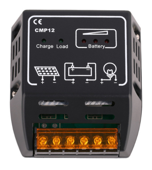
The objective of this blog post to find a way to charge the main battery with the solar panel cells. There are different ways to go about this, but I found that the best way for our project is to use a charge controller. This way we can make sure that we do not overcharge the battery with our solar panel.

The specific charger we are using is called The xcsource Solar charge Controller. This specific one is purchased from amazon.

Figure 1: Top View of Charge Controller

A charge controller is basically a voltage/current regulator to keep batteries from overcharging. It regulates the voltage and current coming from the solar panel going to the battery. Most solar Panels supply more voltage than rated, because these panels need ideal conditions to be able to provide full power, and those conditions are impossible to meet. The panels are designed to provide power than rated, so it can still function in less than ideal conditions. So without regulating the solar panel The battery can be damaged from overcharging.


How it Works

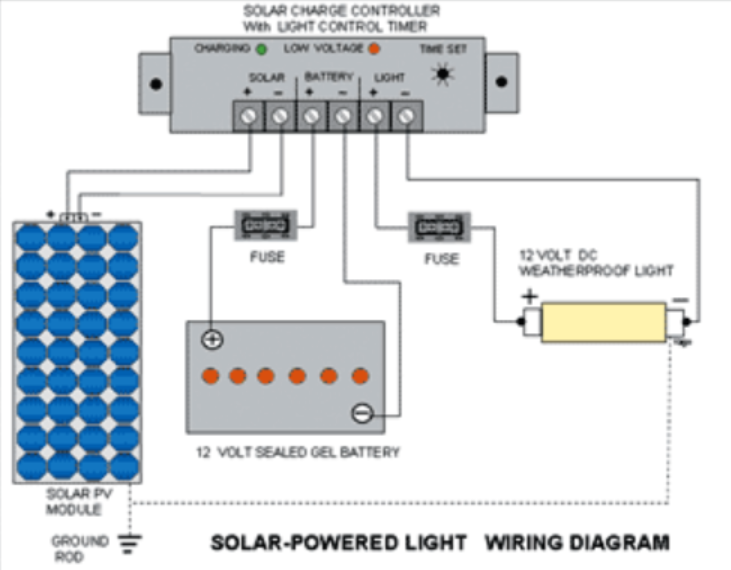
The way that works is we connect the solar panel and the battery to the charge controller. The charge controller will charge the battery and power our components. The charge controller will charge the battery until the it reaches a full charge and as the battery charge gets higher the controller will reduce the solar panel output to avoid overcharging the batteries. Once the battery is nearly full, the charge controller only sends a trickle charge to top off the batteries without overcharging them. This process is known as the off grid charging. An alternative process is to allow the solar panel to supply power to our components directly, but that is not as efficient, and will not be able to supply enough energy for the motors. When the battery reaches a full charge the controller will switch the power output of the solar panels to a dedicated load, such as a light or heating filament.

Figure 2: Typical connection of Solar Panel – Battery Controller


Conclusion

As mentioned earlier the charge controller is mainly used to prevent overcharge, and improving charge quality. But that is not the only advantage of using the charge controller, it can also prevent battery discharge in low or no-light conditions. Discharging can happen when the sunlight goes out the battery will discharge to heat the solar panels. However, the charge controller will detect the batteries discharging and disconnect the panels, to prevent the discharging of the battery. This can also be achieved by using solar panels with blocking diodes that prevent battery discharge during low or no-light conditions, but such systems are not as efficient when using high power solar panels.


References

  1. https://www.batterystuff.com/kb/articles/solar-articles/solar-info.html
  2.  https://www.amazon.com/Controller-Charge-Battery-Regulator-Protection/dp/B010FNO9NU/ref=sr_1_3?ie=UTF8&qid=1525723142&sr=8-3&keywords=solar+controller+10a
  3. https://www.aliexpress.com/item/10A-CMP12-12V-24V-intelligence-Solar-cells-Panel-Battery-Charge-Controller-Regulators/619325690.html?src=google&albslr=119861048&isdl=y&aff_short_key=UneMJZVf&source=%7Bifdyn:dyn%7D%7Bifpla:pla%7D%7Bifdbm:DBM&albch=DID%7D&src=google&albch=shopping&acnt=708-803-3821&isdl=y&albcp=653153647&albag=34728528644&slnk=&trgt=61865531738&plac=&crea=en619325690&netw=s&device=c&mtctp=&aff_platform=google&gclid=Cj0KCQjwodrXBRCzARIsAIU59TK4xse4VJUY-AmA0KTMhI5Mr_pqDeCrQ-Z9OL_oY1lKCcZHztYFMXEaAlqtEALw_wcB&gclsrc=aw.ds
  4. http://uisalumnisage.org/solar-light-wiring-diagram-2/for-solar-light-wiring-diagram/

Stepper Motor Study

By: Adolfo Jimenez (Manufacturing)

Verified By: Jordan Smallwood (Project Manager)

Approved By: Miguel Garcia (Quality Assurance)


Table of Contents

Introduction

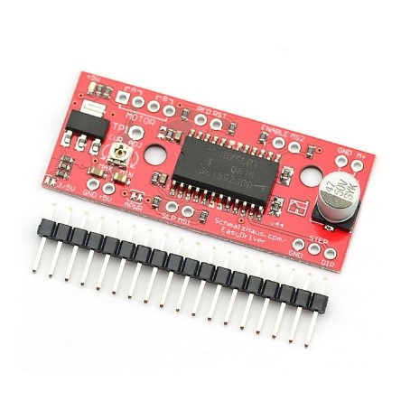
In order to test the articulation of the solar panels before they were assembled onto the chassis an EasyDriver stepper motor driver was used to run and test the motors, and thus by extension the solar panels. Stepper motors can move an exact amount of degrees (or steps) when programmed to do so. This gives us total control over the motor, allowing us to move it to an exact location and hold that position. This is done by alternating power sent to 2 separate coils inside the motor at fractions of a second. A stepper motor combined with a motor driver and microcontroller allows us to dictate the speed and amount of steps taken in any direction making them ideal for our solar panel articulation system.


Parts Used

  • Bipolar Stepper Motor (ROB-09238)
  • EasyDriver – Stepper Motor Driver (ROB-12779)
  • Arduino UNO
  • Breadboard, Wires, 10k Resistor (x2), 12V Power supply

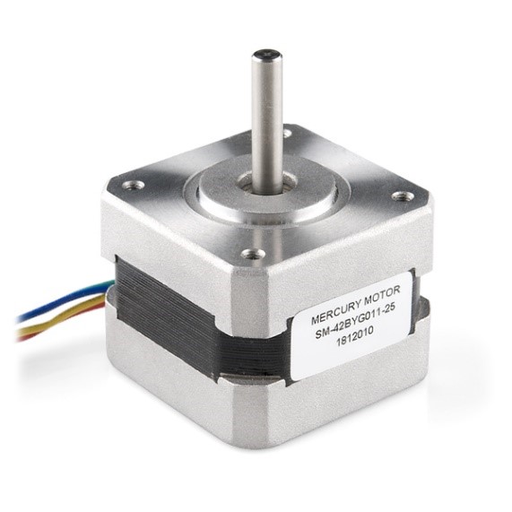
Figure 1: Typical Stepper Motor

Figure 2: Sparkfun Easy Driver


Assembly

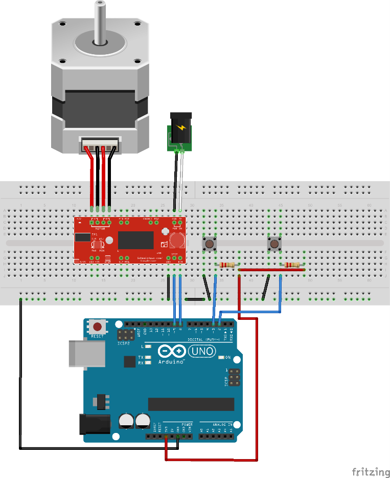
First, the board needed to be assembled, that was a quick and easy job requiring the soldering of the 17 included header pins onto the board. The next step was wiring the entire setup, to do this we first needed to identify which of the four wires pertained to each coil wire pair within the motor. Looking at the datasheet for this stepper motor we can see that the red and green wires form one coil, while the yellow and blue form another. To test this, an LED can be connected to a wire pair on each lead. If the LED blinks while manually turning the motor shaft then those two cables indeed form a coil. The first coil pair should be plugged into Coil A+ and Coil A-, while the second coil pair plugs into Coil B+ and Coil B-. After further research it was discovered that there is no polarity on the coils, so you need not worry about plugging in a coil backwards onto the board. As per the specifications on the datasheet for the motor, a 12-volt power supply was selected to power the motor. All remaining connections can be seen in the following fritzing diagram:

Figure 3: Fritzing Diagram for Simple Stepper Motor Operation


Code

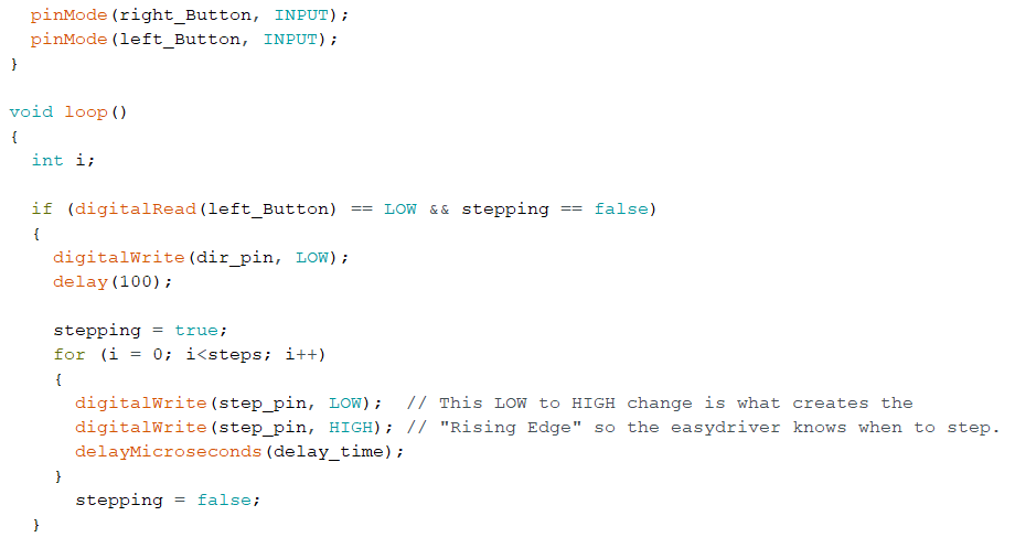
With the physical circuit built the following code was uploaded onto the Arduino UNO to begin controlling the motor. When the code is running, it waits for a button press (a LOW on Arduino pin 2 or 3) and then begins to rotate the stepper motor for the programmed number of steps. A push button switch was added between Pins 2, 3, and ground, with an accompanying 10K pull up resistor used for each pin at 3.3V. For this set up, pin 3 associated with the button on the left (LOW on pin 3) turned the motor clock wise, the button on the right (LOW on pin 2) rotated the motor counter-clockwise.

Figure 4: Code for Simple Operation of Stepper Motors


Conclusion

Utilizing this described setup I was able to test the stepper motors and begin working on the solar panel articulation for our rover. Messing with the code I found that using the motor at slower speeds appeared to provide me with more torque as spinning it at a slower RPM provided the greatest resistance against pressure applied on the shaft by squeezing it with my fingers. One thing to really note is the current adjustment potentiometer on the EasyDriver. I recommend that while the code is running, with a small screw driver slowly turn the potentiometer one way or the other. Depending on the type of motor you use (mainly its coil resistance) you may notice a difference as different current values might operate the motor much more smoothly than others.


References

  1. https://www.sparkfun.com/datasheets/Robotics/SM-42BYG011-25.pdf
  2. http://www.schmalzhaus.com/EasyDriver/Examples/EasyDriverExamples.html
  3. https://www.sparkfun.com/tutorials/400
  4. https://learn.sparkfun.com/tutorials/easy-driver-hook-up-guide?_ga=2.95969304.586601746.1525205163-1420080731.1522797085

Custom PCB for Solar Panels

Author: Diane Kim (Division Manager of E&C Hardware)

Verified By: Jordan Smallwood (Project Manager)

Approved By: Miguel Garcia (Quality Assurance)


Table of Contents

Introduction

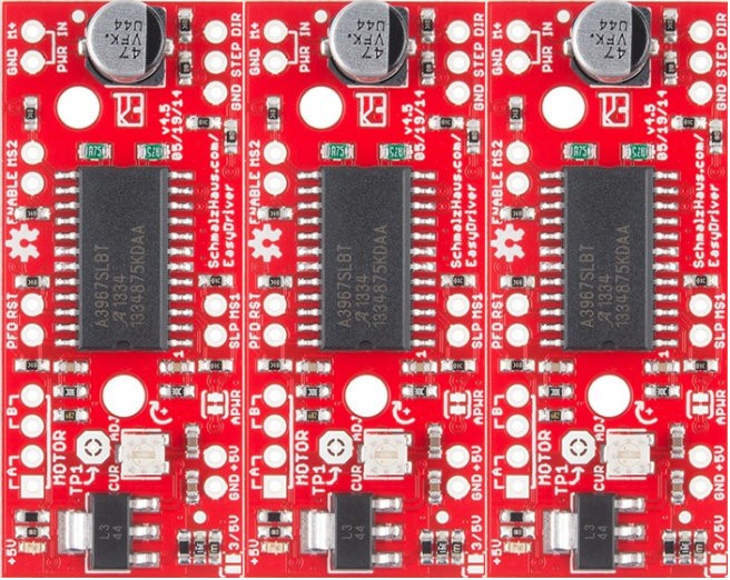
The second PCB is for the solar panels which consists of the connection for the stepper motor drivers (3), current sensors (6), and GPIO expander. We are using the stepper motor from Sparkfun therefore we decided to go with the stepper motor driver associated with it—the EasyDriver. Although we wanted to implement the circuit itself, the IC that is used for the EasyDriver was not available, therefore we are going with the shield. To decrease the pins from the EasyDriver to the ATmega2560, we are using the I2C bus for the EasyDriver and the current sensors.


Stepper Motor Driver Connection

The connection from the EasyDriver to the ATmeag2560 are the MS1, MS2, DIR, ENABLE, and STEP. The Eagle file for the EasyDriver schematic can be found on Sparkfun’s website. The 3 stepper motor drivers are placed side-by-side horizontally.

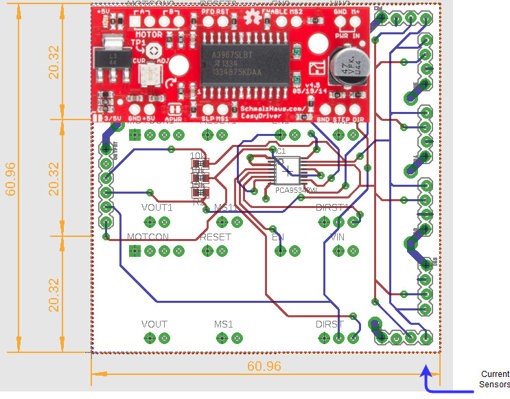
Figure 1: Placement of the Stepper Motor Driver

Figure 2: Placement of Motor Drivers on Solar PCB

  • MS1 and MS2

MS stands for micro-step and is used to determine the resolution of the step. For our specific design, we will be setting both MS1 and MS2 to ground or both to low since we don’t need high resolution to fold and unfold the solar panels.

Figure 3: Truth Table of MS1 and MS2 Resolution

  • DIR & ENABLE

The DIR pin is a logic input that determines the direction of the stepper motor. The ENABLE pin is a logic input that determines whether the IC drives the motor. These two inputs will connect with the Atmega2560 by the I2C bus.

  • STEP

STEP is a logic input that is triggered when the pin goes from high to low. The STEP is connected between all three motor drivers since they will all be operating at the same time.


I2C Bus

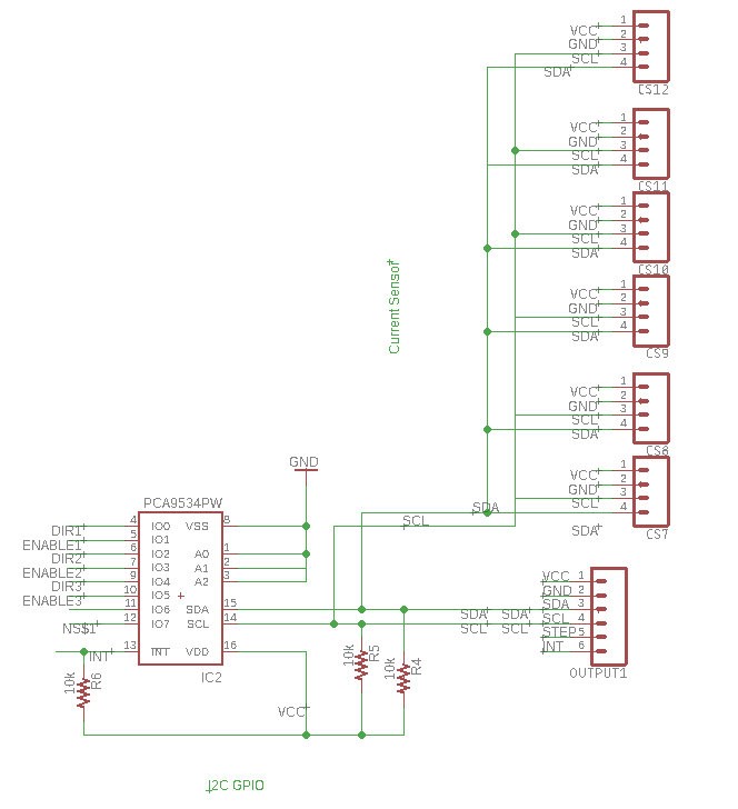
I2C connection uses the two connections SDA and SCL to connect between the master and the slaves. If we didn’t go with the I2C connection, we would have needed 7 wires from the stepper motor driver to the ATmeaga2560. By using the GPIO expander, we connect DIR and ENABLE for all 3 stepper motor driver to SCL and SDA. For our circuit, we are using the TCA9534APWR chip from Texas Instruments. Each I2C bus needs a pull-up resistor for both SDA and SCL. In addition to the SDA and SCL from the GPIO expander, we are adding the SDA and SCL from the current sensors to the I2C bus. We are using the 1NA3221 Breakout Board from Switch Doc which has four programmable addresses.

Figure 4: I2C Bus connection of Stepper Motor (DIR and ENABLE) and Current Sensors)


Final Version of the PCB

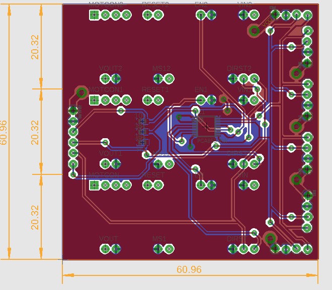
Figure 5: Final Version of PCB with Copper Ground and Power Planes

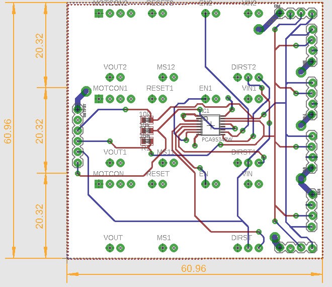
Figure 6: Final Version of PCB without Copper Ground and Power Planes


Conclusion:

The Solar Panel PCB was never tested due to the solar panel mechanism never being completed.


References

  1. Eagle File: https://drive.google.com/open?id=1-hPQAabUNwHn-SUBNcfJ6V6lTwZHwjUo under SolarPanelShield.brd and .sch
  2. I2C Bus: https://learn.sparkfun.com/tutorials/i2c
  3. Stepper Driver: https://www.sparkfun.com/products/12779

Custom Chassis PCB

Author: Diane Kim (Division Manager of E&C Hardware)

Verified By: Jordan Smallwood (Project Manager)

Approved By: Miguel Garcia (Quality Assurance)


Table of Contents

Introduction

Unlike many of the other projects that are required to use the 3DoT board, we will be using the ATMega 2560 due to a large amount of connections. Since many of the interconnections are from pin to pin, specifically the motor drivers, we have made a custom shield to route many of these signals. 

Table 1: Side view of the Design for the Custom Circuit


Aside from the connections to the peripheral devices that are mentioned above, the custom PCB for the chassis has the buck converter that will convert the 12v from the battery to 5v to supply power to the ATmega2560.


Design of the PCB

Buck Converter

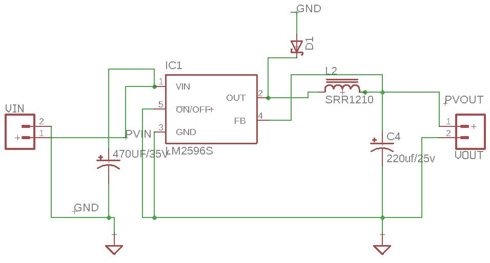
Through a different experiment, we confirmed that we will be using the LM2596 buck converter. Since we will be converting between a fixed voltage of 12v to 5v, we are using the fixed output design from the datasheet.

Figure 1: Typical Schematic of the Fixed Output Buck Converter

Based on the datasheet, the Cin , Cout, and inductor value was determined. The capacitors also have to be low-ESR or impedance for the circuit. The traces that are drawn with bolded lines must be kept short and thick for better results.

  • Cin: 470uF/35v
  • Cout: 220uF/25v
  • Inductor: 68uH/3.10A

Figure 2: Eagle Schematic of the LM2596

Connection for the Motor Driver

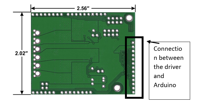
Figure 3: Dimension of Pololu dual VNH5019 motor drive

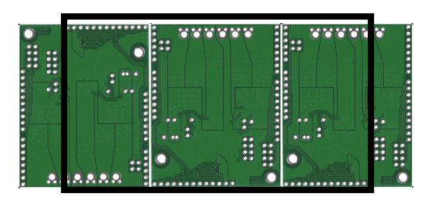
We are using the Pololu dual VNH5019 motor driver for the Pathfinder. Since we are limited to a 5×4 cm (WxL) board, due to limitation’s of the PCB fabrication machine we are using, we have decided to place the connectors so that the board doesn’t exceed the maximum size. The drivers are placed vertically so that the width of the PCB doesn’t exceed 5 cm.

Figure 4: The Overview of how the motor drivers are placed The black outline is the line of dimension of the shield so that it doesn’t exceed 5 cm.

Connection’s of the other peripheral systems

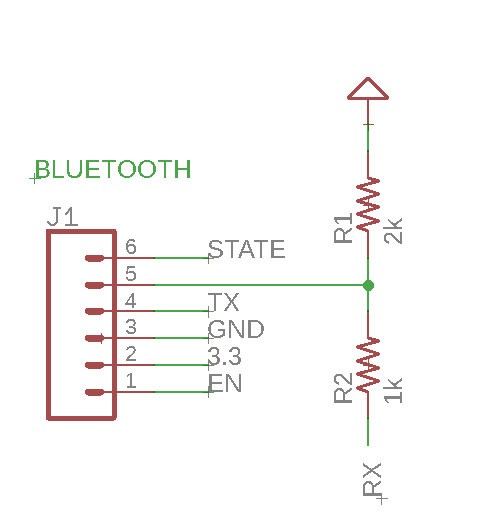
We initially thought about making the HM-10 Bluetooth module a part of our PCB circuit, but we instead decided to use the breakout board and use connectors. Since the RX of the Arduino can only take in 3.3v and the TX of the HM-10 outputs 5v a voltage divider was used. To get 3.3v from 5v, we used 1k and 2k resistors.

Figure 5: Level shift resistor for the HM-10 connection to RX of Arduino Mega

  • The current sensors are used to measure the amount of current from the motors. Although there are current sensors in the motors, the lower limit of the amount of
    current is not low enough for our no-load protocol. Therefore these current sensors will be connected to the motor drivers and the motor’s pin for the current will be routed through these current sensors. We used the Adafruit INA169 DC current sensor breakout board.
  • Other peripheral devices are the ones mentioned above: motor drivers (3), shaft encoders for the motors (6), ultrasonic sensors (2), servo motors (2), LEDs (2), fan, HM-10 (Bluetooth), current sensors (6), and stepper motor drivers (3). The connection is based on the interface matrix. The connectors are placed on the outer part of the shield so that the motor drivers do not cover the connections.

Final Version of PCB

Figure 6: Eagle File for Final Chassis PCB with ground pour

Figure 7: Final Chassis PCB without Ground Pour


The board was very simple to design since it essentially connected all the systems together, however, there were some considerations that needed to be accounted for. The size of the board was restricted to 4″ by 5″ due to the fabrication machine used. Since the motor drivers had to be placed horizontally and the board was a shield for the ATmega2560, the positions of the connectors were fixed and some of the traces had more resistance than the shorter wires. In addition, the ground and the power
planes needed to be laid out so that there is a good connection. This means that ground vias were added and the trace for the power was thicker than the traces for transmitting data. Another problem that arose was the connection between the pads and the connectors. The connectors did have a connection but it was easily disconnected if a small force was applied to it.


References

  1. EAGLE File: https://drive.google.com/open?id=1-hPQAabUNwHn-SUBNcfJ6V6lTwZHwjUo under MotorDriverShield_aaproved.brd and .sch
  2. Buck Converter: http://www.ti.com/product/LM2596
  3. Motor Driver: https://www.pololu.com/product/2502

Motor-Mock Up

By: Jordan Smallwood (Project Manager)

Approved by: Miguel Garcia (Quality Assurance)


Table of Contents

Introduction

One of the requirements of the Pathfinder is to determine whether a no-load condition is present, we needed to define what that condition is. In order to test the characteristics of our motor a simple experiment was conducted. The idea is that we wanted to control the load to the motor under a constant voltage and extract the current from the Arduino.


Setup

Appropriate connections were made to interface the Arduino to the VHN 5019 motor drivers so that we could read the output voltage from the onboard current sensors. To communicate with the Arduino through MATLAB we needed to install an add-on package called, “MATLAB support package for Arduino Hardware”. This add-on is very simple to use and eliminates the need for uploading code through the Arduino IDE. It allows for direct control of the Arduino through the serial port and MATLAB has predefined functions that allow for this.


Software

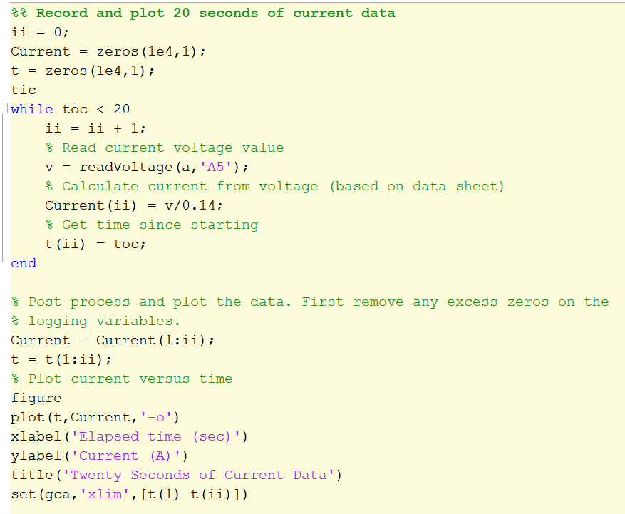
Figure 1: Code for Plotting Motor Current Draw

The code is very simple, it is a while loop that compares the current time with the limited time. While in the loop it reads the analog voltage from the current sensor and then stores that value in a vector that has a corresponding time stamp. After this you can apply some smoothing features to the plot such as an n-point moving average so that we don’t see all the discontinuities.


Results

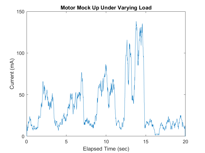
Figure 2: Results from Motor Mock Up


After applying a 25 point moving average this is the result. I applied a resistance to the wheel with my hand about every 5 seconds or so and as you can see, the spikes are where the load was applied. This is very good information for us since we know that the motor under no-load is about 30 mA. In addition, these motor’s have much less current draw than the previous motors on the Pathfinder. In order to get accurate results when applying this to the final mission, we will need to apply an averaging filter to ensure we don’t turn off the motors when they are actually experiencing a load.


References

  1. https://www.mathworks.com/videos/plotting-live-data-of-a-temperature-sensor-using-arduino-and-matlab-121317.html
  2. https://www.mathworks.com/hardware-support/arduino-matlab.html
  3. https://www.pololu.com/product/2502

No-Load ISR

By: Jordan Smallwood (Pathfinder Project Manager and Electronics & Control)

Approved By: Miguel Garcia (Quality Assurance)


Table of Contents

Introduction:

The idea is that if any of our motors are under a no-load condition we want to cease power to that motor, since it makes no sense to waste power on a freely spinning motor. In order to do this we will need to understand the conditions present when our motor is experiencing no-load. This is determined in the motor-mock up study found HERE. Since current is proportional to the load that the motor is experiencing we can check the current to each motor and compare with the conditions. This will be implemented with an internal timer interrupt.

The robot will not be travelling that fast and we can set a timer interrupt with a period of 100 ms that will check the motor conditions every 0.1 seconds. Also, one of the things to keep in mind is that we need to know when the motor is ready to have power reapplied to it. So whenever we enter this interrupt routine we will check any of the motors that are off to see if a load is present.


Software:

Intro to Timers:

In order to set up the timer based interrupt we need to briefly overview internal interrupts. Internal interrupts make use of the Arduino timers, for the Mega we have 6 timers. Any time you decide to make use of a timer it is paramount that you make sure it is not already in use or that pins associated with that timer are not being used (e.g PWM pins). There are two different size timers on board the Arduino, 8-bit and 16-bit, depending on the resolution needed. Also, all of these timers depend on the internal clock of the Arduino which may be 8 or 16 MHz depending on what board you are using. In my experience always leave timer0 alone, it is used heavily within functions and is best left untouched.


Timer Registers:

Figure 1: Timer/Counter 5 Control Register A

Figure 2: Timer/Counter Control Register B

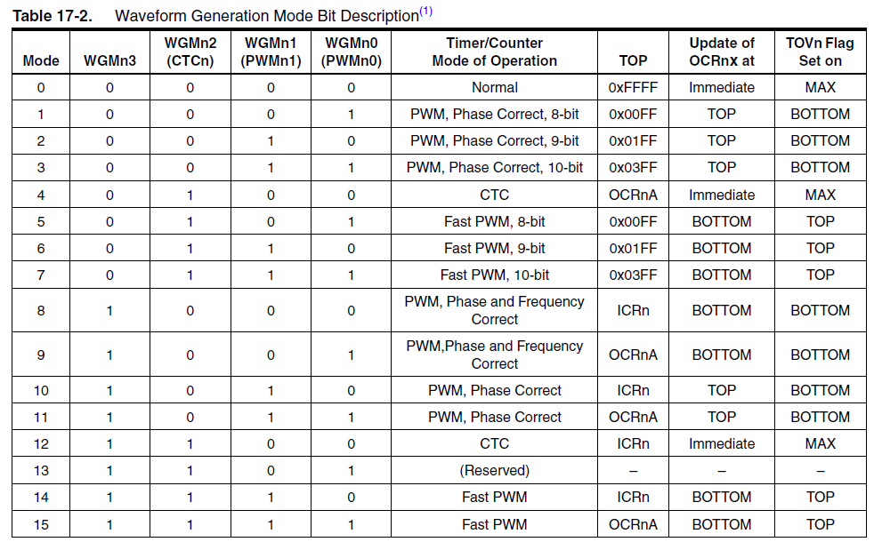
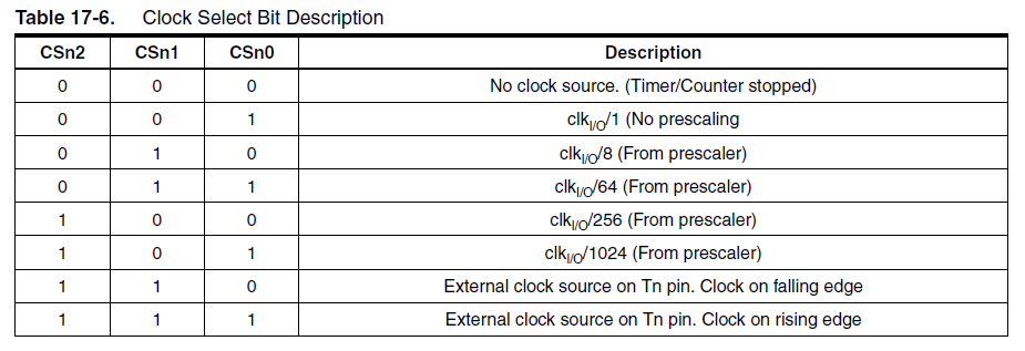
These 2 registers contain all the bits that describe the function of your timer. The only bits that we will be concerned with are the WGMnX and CSnX bits. The others become more complicated and there is not need for them with what we are trying to do. For our purposes we will have the timer in CTC mode (Clear Timer on Compare Match) and we will load a certain prescaler depending on the desired frequency. Note that this can be done in normal mode in which we preload the timer with a value and set up a timer overflow interrupt. However, we chose to do CTC mode. The tables below describe the various modes and prescalers:


Table 1: Waveform Generation Mode Bit Description/Truth Table

Table 2: Clock Select Bit Description/Truth Table

              If we are using the CTC mode then we can realize that we need the following line of code:

Figure 3: Setting Timer 5 to CTC mode

              The following scheme can be used to determine the value to compare the timer with and the required prescaler.

  1. Find CPU Frequency (16 MHz)
  2. Find Max Counter Value (16-bit Timer -> 65536)
  3. Divide CPU Frequency by Selected Prescaler (16MHz/256 = 62.5kHz)
  4. Divide Result by Desired Frequency (62.5kHz/10Hz = 6,250)
  5. Verify that this is less than max counter value (6,250 < 65536)

Now that we realize a prescaler of 256 will do the trick we can examine the truth table for the prescalers and find that a value of 0b100 corresponds to that prescaler. So then the following line of code can be implemented:

Figure 4: Loading Prescale Value Into Timer Control Register

Figure 5: Output Compare Register 5A

Since we have set up the timer frequency and mode of operation now we need to load the value to compare the timer with. As mentioned earlier we found that the value to compare the timer with was a count of 6,250. So, we will include the following line of code:

Figure 6: Loading Output Compare Register

Now all that’s left to do is enable interrupts within the timer 5 interrupt mask register. Here is what the register description looks like:

Figure 7: Timer/Counter 5 Interrupt Mask Register

Since we are only using channel A on timer 5 we will set the corresponding timer compare interrupt enable with the following line of code:

Figure 8: Enabling Timer 5 Output Compare Interrupt

Finally we have a timer driven interrupt that is capable of checking the motor conditions and will be able to turn on or off power to the motors. This is done every 0.1s and all that’s left to do is write the ISR corresponding to this interrupt.


Interrupt Service Routine:

The original idea behind this interrupt was to check the condition of the motors. The motor drivers have current sensors on them that are mapped to pins on the mega. These current sensors have an output voltage that is approximately 140mV/A passing through the motors. We can determine the current through the motors with an analogRead() function and realizing the current is some factor of that.

Figure 9: Calculating Current From Current Sensors

Since the resolution of the ADC is not that great, at least with respect to our reference voltage, the output of the current sensors will be limited to steps of about 35 mA. Which means that our reading will be off by at most 17.5 mA.

Now that we know how to read the current we need to turn off the motors that are below the no-load current threshold. We can do this with a simple IF statement:

Figure 10: Code to Check if Motor is under No Load Condition

The next thing to realize is that if a motor is already off we need to check if it is experiencing a load. This will be done by setting a flag, that is any time we turn a motor off we will want to turn it back on in the next interrupt and check if it is still in a no-load condition:

Figure 11: Code for Checking if Motor is Still Under No-Load

Note that in order to avoid conflicts with the 6 Wheel Electronic Differential we need to save the last known speed of the motor so that when we turn the wheel back on it doesn’t try to go full speed.


Conclusion:

In order to implement this type of control a timer based interrupt service routine is a good choice. We could have used different methods, but we know that this will not happen that often. Setting a timer to check this condition was a simple but effective solution. Also, utilizing a Finite State Machine in the ISR is a promising idea because we want to be able to determine when the wheel is ready to be turned back on.


References:

  1. http://ww1.microchip.com/downloads/en/DeviceDoc/Atmel-42735-8-bit-AVR-Microcontroller-ATmega328-328P_Datasheet.pdf
  2. https://www.pololu.com/product/2502
  3. https://www.robotshop.com/letsmakerobots/arduino-101-timers-and-interrupts