By: Jordan Smallwood (PM), Diane Kim (E&C), Mohammad Yakoub (MST), Adolfo Jimenez (Manufacturing)
Approved by: Miguel Garcia (Quality Assurance)
Project Overview
By Jordan Smallwood
Project Objective:
The Pathfinder is a project that has been passed down from generation to generation. The originators built the chassis and original idea back in the fall semester of 2016. A rover like this does not make its way into the EE department that often since the lot of us don’t typically have much experience with welding and fabrication. Luckily enough for our group we will be picking up the slack where the previous teams had left off. It seems as though every semester that attempts this project faces failure in one way or the other whether it is the differential rocker-bogie mechanism or leaving wires exposed to short the 12V golf cart battery. Either way, the overall aim of this project is to finally finish what other groups have started and that will be defined in the following sections of this report.
Mission Objective:
By Jordan Smallwood
The Spring of 2018 Pathfinder will follow the path laid down by previous Pathfinders. The mission will begin in front of the CSULB library where the rover will exit its cocoon state. The rover will then proceed to begin its journey through campus, a 0.09 mile journey to its charging station. There will be 10 predefined GPS checkpoints along the way and the rover will traverse a flight of stairs. Once the rover has arrived at the charging station it will begin to track the sun and provide the Arxterra user with up to date battery level conditions. Specifically the Pathfinder will demonstrate the following:
- Custom solar panels capable of tracking the sun and exhibiting optimum orientation so that battery charge takes the least amount of time.
- The rover will be able to enter and exit a cocoon state. The term cocoon state implies that the solar panes will fold up so that in the event of a dust storm the solar panels will not become damaged. This state will be entered if the rover is in launch, a dust storm or whenever the rover is operating over steep terrain.
- The rover will be able to communicate with the Arxterra app providing information like battery level, panel angles, panel voltages and charging current.
- The solar panels will have a form factor identical to those of the Spirit and Opportunity Mars Rovers.
- The rover will exhibit a 6-wheel slip differential for turning and traversing rough terrain. Since the robot will be climbing over random objects, some wheels will not require the same speed as other wheels and this needs to be considered while operating the rover.
- Demonstration of GPS navigation with obstacle avoidance.
- The course mapped out by F’16 and S’17 will be the same course for S’18.
- There shall be no modification to the rover that stands in the way of high desert operation.
Project Requirements
By Jordan Smallwood
Level 1 Requirements
- The pathfinder will travel a 0.09 mile course. This course includes going up a set of 3 stairs at a 70 degree incline and another set of 3 stairs with a decline of 70 degrees.
- Pathfinder shall launch from a cocoon state
- The Pathfinder will enter and exit the cocoon state by Arxterra app user input.
- Pathfinder shall allow the user to enter the “articulate state” program module which will be available once the Pathfinder has exited its cocoon state. This sequence will direct the solar cells at the proper orientation to allow max charge of the battery.
- The Pathfinder will update the user with information about panel angles, GPS location, battery level and charge current when in the “Articulate state”.
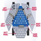
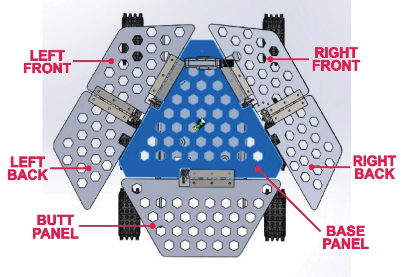
- The overall solar panel system will consist of two side panels, a rear panel and a base panel.
- The solar panel design will be identical to those of the Spirit and Opportunity Mars Rovers.
- A 6-wheel electronic slip differential shall be implemented
- Wheels under a no-load condition will be considered and power to that motor will be decreased.
- The Pathfinder shall demonstrate obstacle avoidance while making its journey through campus.
- Any modifications made to the Pathfinder shall not inhibit the rover’s ability to operate in high desert condition.
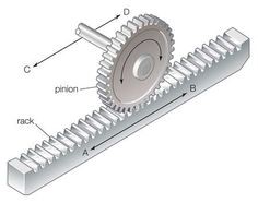
- Rocker bogie mechanism shall be improved by implementing a differential gear-box system as opposed to the differential bar.
Level 2 Requirements
By Jordan Smallwood
- Course Duration
- The power budget of our overall design will determine the duration of our course, once this has been completed the actual distance traveled will either be verified by this or will have to be changed to a shorter distance.
- In order to travel up these stairs our mass report along with our motor mock up will verify that this can be accomplished.
- Cocoon Launch
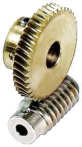
- To perform the cocoon state function the solar panels will be mounted to worm gears attached to DC stepper motors to ensure smooth operation.
- Enter/Exit Cocoon State
- The Pathfinder shall communicate via Bluetooth with the Arxterra user and will have an interface allowing the user to enter/exit the cocoon state.
- Articulate State
- The articulate state module will adjust the positions of the solar cells using a proportional controller.
- The proportional controller will accept the charge rate as an input and will output changes in orientation.
- Telemetry
- While communicating with the user via Bluetooth on the Arxterra app the Pathfinder shall respond with packets of information related to this information.
- Solar Panels
- These four panels will be constructed of aluminum such that the rover can operate in the harsh desert conditions typical of Mars.
- The side and rear panel’s will be capable of position orientation to enter and exit the cocoon state and also optimize battery charge
- Solar Panel Form Factor
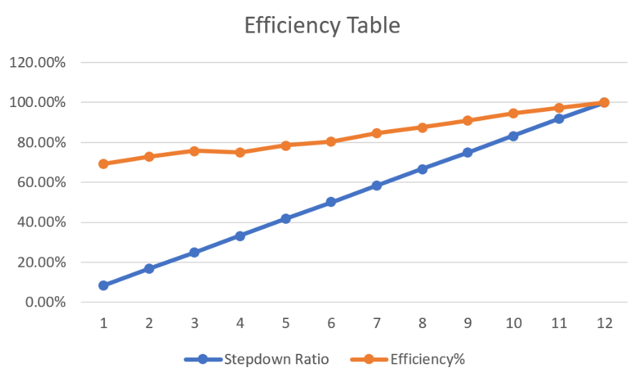
- 6-Wheel Electronic Slip Differential
- A coded differential will be used ensuring that the wheels are spinning at the same rate.
- IR range sensors will be mounted to the motors to determine the velocity of the wheels
- Current sensors will be used to determine the load on the wheels
- No Load
- To conserve energy, the rover will stop rotation of a freely moving wheel using the current sensors
- Obstacle Avoidance
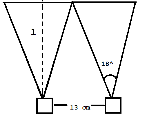
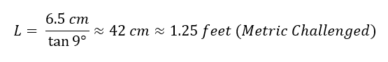
- Ultrasonic sensors will be used to determine if an obstacle is in its path.
- An obstacle avoidance routine shall be implemented.
- The rover will not make any attempt to climb an object that it is unable to clear
- Modifications
- Rocker-Bogie Mechanism
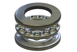
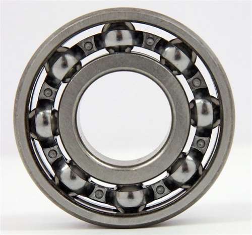
- The differential gear box will be constructed of three miter gears, three machined shafts, six mounted bearings and shaft collars
- This mechanism will be mounted below the Pathfinder and enclosed in an aluminum box with the electronics.
- This box shall be easily removed for inspection and maintenance.
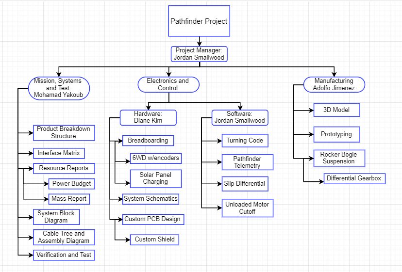
Work Breakdown Structure
By Jordan Smallwood

Figure 1: Work Breakdown Structure for Pathfinder Project
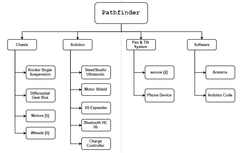
Product Breakdown Structure
By Mohammad Yakoub
Verified By: Jordan Smallwood

Figure 2: Product Breakdown Structure for Pathfinder Project
Resource Reports
By Mohammad Yakoub
Verified By: Jordan Smallwood
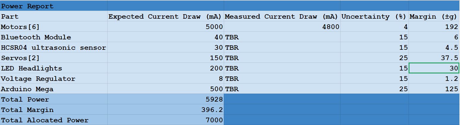
Power Report:

Figure 3: Preliminary Power Budget
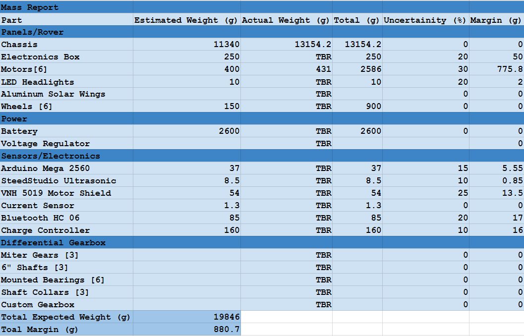
Mass Report:

Figure 4: Preliminary Mass Report
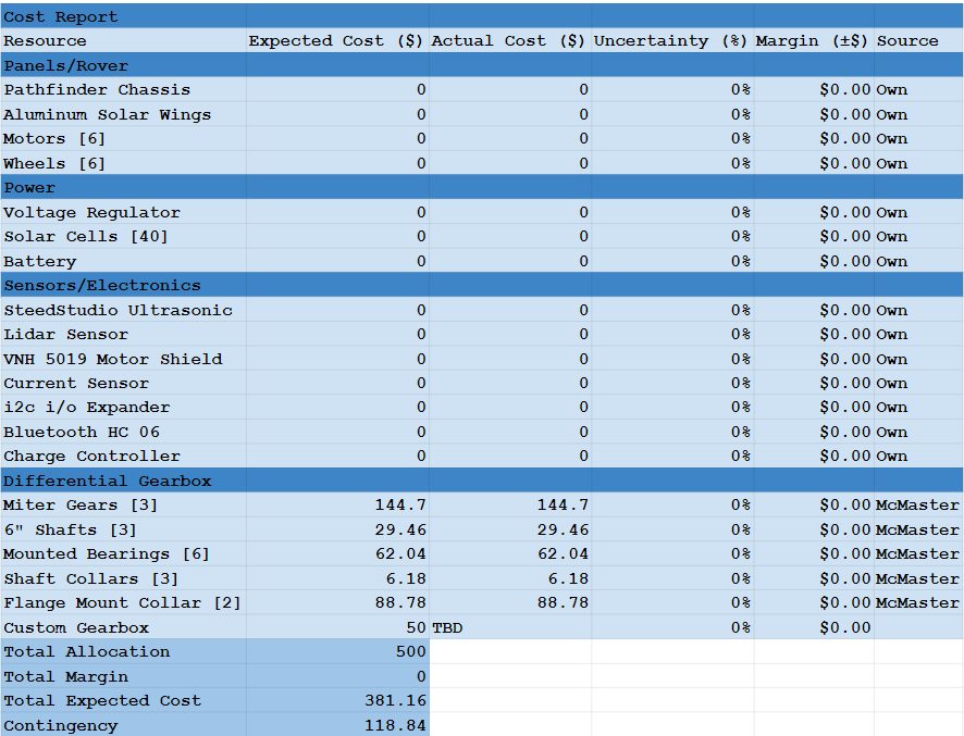
Cost Report:

Figure 5: Preliminary Financial Report
System Block Diagram
By Mohammad Yakoub
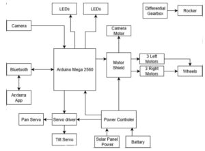
Figure 6: Preliminary System Block Diagram
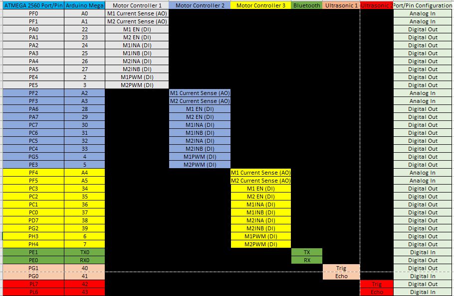
Interface Matrix
By Jordan Smallwood
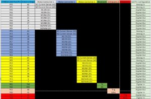
Figure 7: Preliminary Interface Matrix
Software Design
By Jordan Smallwood
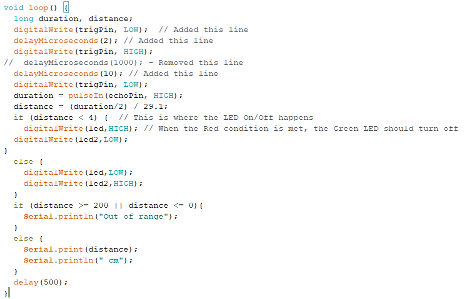
- Obstacle Avoidance: In order to make sure that the Pathfinder does not fail the mission, ultrasonic sensors will be used in the front of the rover to verify that an object is not too large for Pathfinder to climb over. This routine will take place within the software and more information will be provided at a later time.
- GPS Checkpoint Navigation: Pathfinder will use GPS location information from the on-board iPhone or Android device and follow the course as defined in the mission objective. This will involve some type of digital controller and will be implemented in software. Again, these are preliminary concepts and not much has been constructed as of now but will be provided as the semester continues.
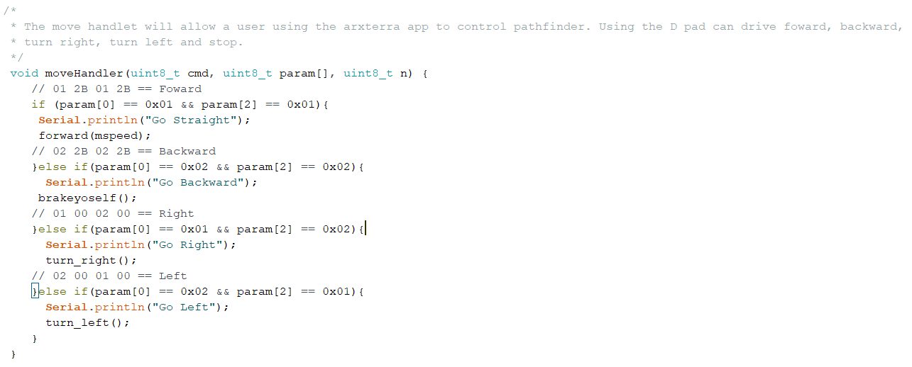
- Motor Functions: Pathfinder will perform very basic motor functions such as go straight, turn around, turn left, turn right and stop.
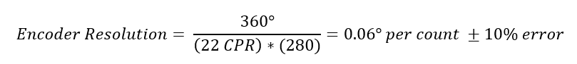
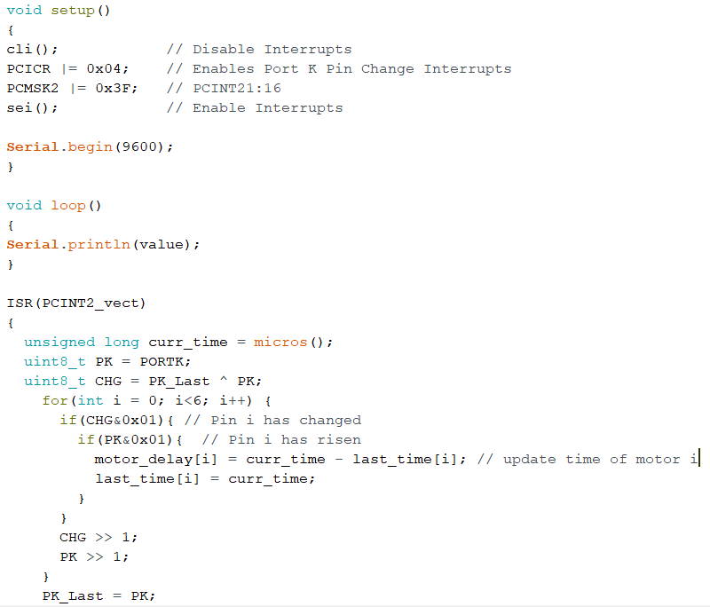
- Read Encoders: To determine the speed that each wheel is spinning this function will examine the current speed of each wheel by counting the pulse trains given from the IR sensors mounted to the wheels.
- Stop Motors Under No-Load: By examining the current associated with each motor we can make sure we are not spending energy for nothing. This will most likely be a conditional statement and if the current state of the motor is under a no-load condition, then the power supplied will be cut off. Reinitializing the motor speed once a load is present will have to be tested though.
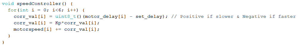
- 6-Wheel Differential: When making a turn the speeds of each motor needs to be considered since they may be traveling along different paths but need to arrive at the destination at the same time. By examining the speeds of the motors we can modify the PWM signal applied to ensure that we are traveling smoothly.
- Exit Cocoon/Articulate Solar Panels: When the user decides to either exit or enter the cocoon/articulate state the microcontroller will apply the functions necessary to do so.
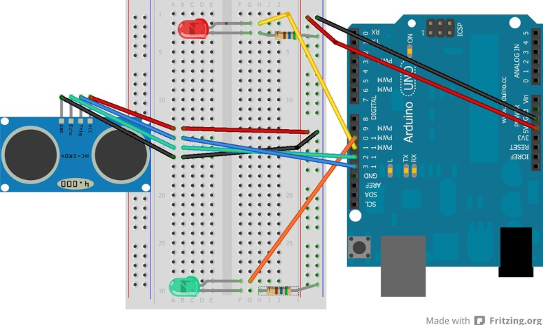
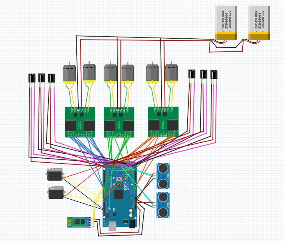
Fritzing Diagram
By Diane Kim
Verified By: Jordan Smallwood

Figure 8: Fritzing Diagram
The components inside the chassis contains the following: batteries (2), dual motor drivers (3), ultrasonic sensors (2), servos (2), IR sensors (6), motors (6), and the Arduino Mega 2560 (1). Unlike the previous version which only had 1 battery, we will be using 2 batteries to power up the motor to decrease the size. The ultrasonic sensors are used to navigate the rover. The IR sensors are to be placed beside the wheels to measure the RPM by toggling the signal whenever the spoke of the wheel passes by. The VNH2SP30 dual motor drivers is used to control the speed of the motors thus the wheels. The servos are used for the pan tilt. All the peripheral systems are connected to the Arduino Mega 2560 to input and output signals.
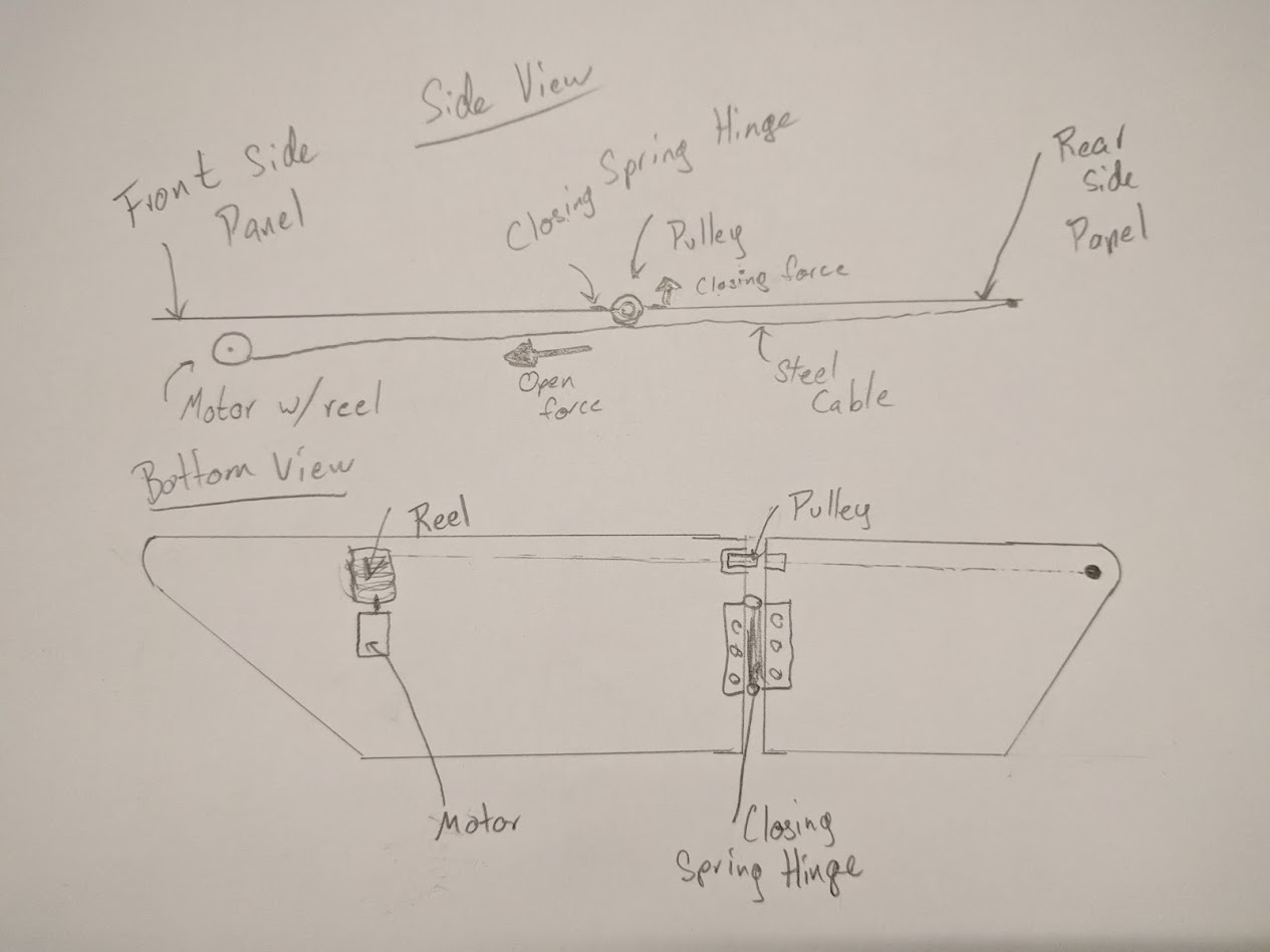
Mechanical Design
By Adolfo Jimenez
Verified By: Jordan Smallwood
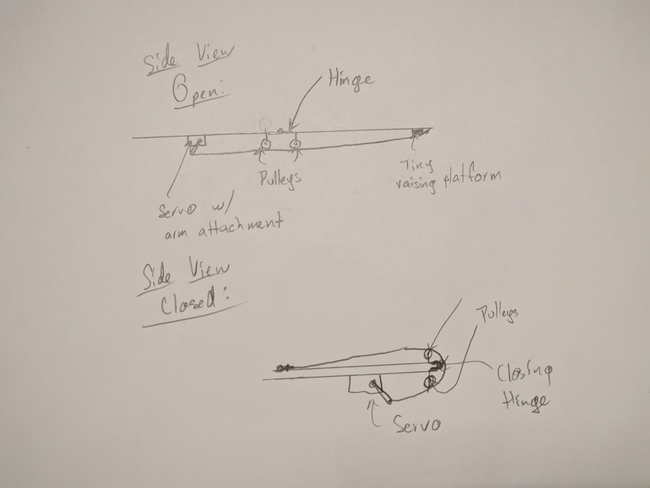
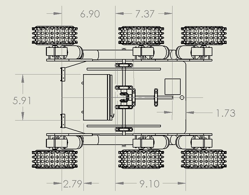
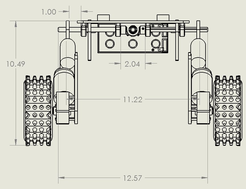
2D Drawings (Dimensions all in inches):
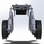
Rear and Top Side View:


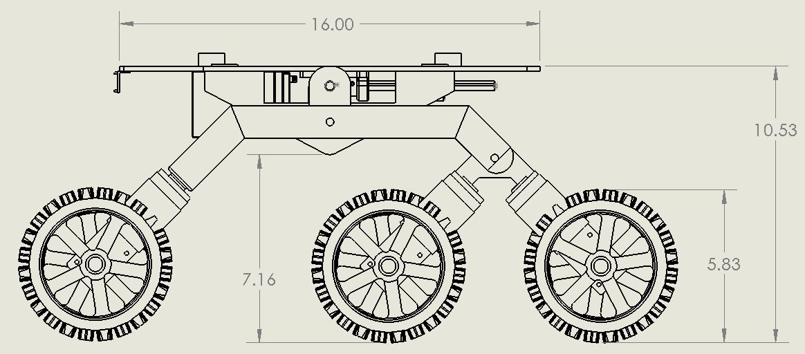
Side View (left):
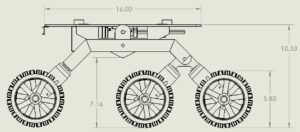
Figures(9,10,11): 2D Layouts of Physical Structure
For the pathfinder project, since we are mainly building upon the design of previous semesters most of the dimensions and physical parts will remain the same. The main design difference for the time being is the addition of a differential gear box. Whereas previous semesters utilized a barely functioning differential bar, this semester, we decided to remove the bar entirely and replace it with a much more functional differential gear box. This addition of a differential gear box will offset the wheel assemblies by about .8 Inches on each side and raise the main platform about .38 inches higher off the ground.
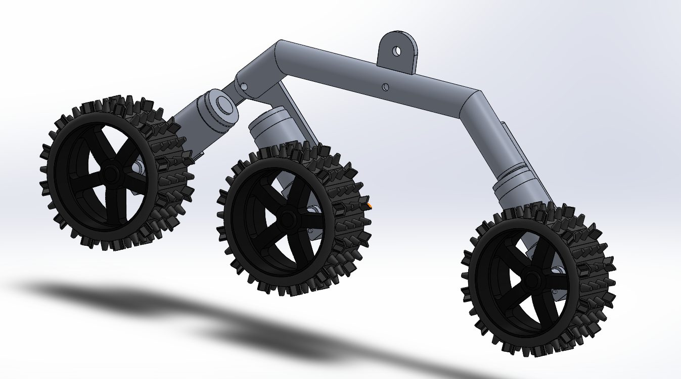
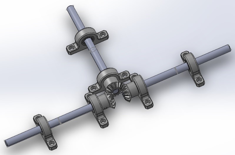
Differential Gear Box


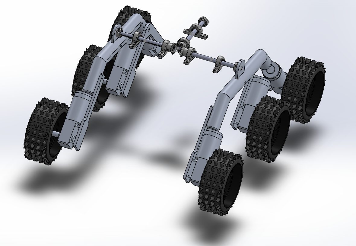
Figures(12,13,14): 3D Layouts of Physical Structure
Two planar aluminum tubes for the rocker boogie suspension system are connected to each other by a differential mechanism. When one side changes in pitch say for instance one side begins climbing over an obstacle, this mechanism rotates the main body around the rocker joints by an average angle of two sides. Gear A connected to the left, gear B connected to the right and gear C is assembled on the main platform. In differential mechanisms, all gear ratios are the same. That means if gear A rotates 10 degrees and gear B rotates 20 degrees, the main platform will rotate 15 degrees.
Verification and Validation Plans
By Mohammad Yakoub
Verified By: Jordan Smallwood
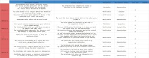
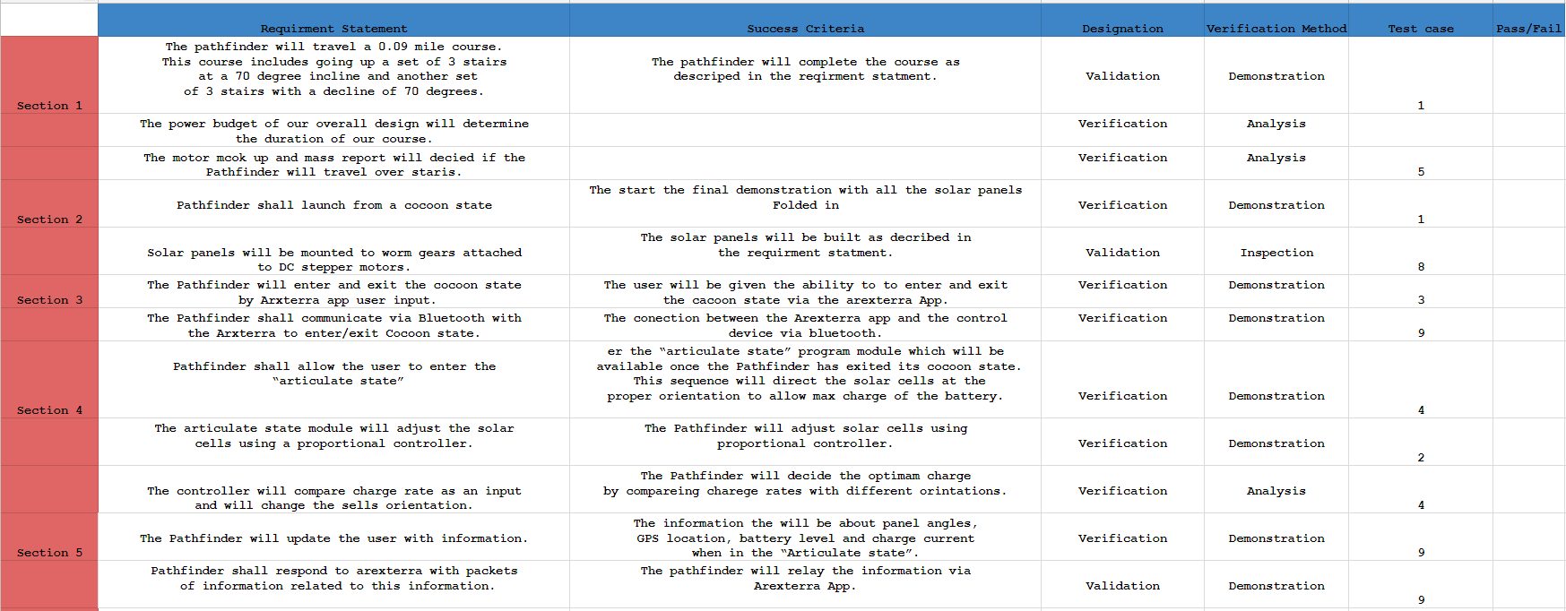
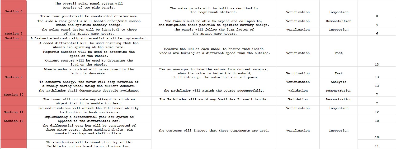
Figure 15: Verification and Validation Part 1

Figure 16: Verification and Validation 2
Test
By Mohammad Yakoub
Verified By: Jordan Smallwood
3.3.1 Final Run
Description: The Pathfinder will follow a course That is 0.9 miles in length. The course will includes going up a set of 3 stairs at a 70 degree incline and another set of 3 stairs with a decline of 70 degrees. The robot will start the course in a cocoon state and will deploy solar panels.
Test Environment: Outside the classroom
3.3.2 Proportional Controller
Description: The Pathfinder will adjust solar cells using proportional controller.
Test Environment: Inside a classroom
3.3.3 Cocoon
Description: User will use the Arxterra App to enter and exit cocoon mode.
Test Environment: Inside a classroom
3.3.4 Articulate Mode
Description: The user will use the arexterra App to activate ‘articulate mode’, and receive feedback from the Arxterra App.
Test Environment: Outside the classroom
3.3.5 Weighting
Description: Placing the fully assembled Pathfinder on a weighing scale.
Test Environment: Inside a classroom
3.3.6 Scale
Description: Goliath should resemble the ‘Spirit Mars Rovers’
Test Environment: Inside a classroom
3.3.7 Obstacle Avoidance
Description: The Pathfinder will avoid obstacles while running the final course.
Test Environment: Outside the classroom
3.3.8 Solar panels
Description: The Pathfinder solar Panels will be made out of metal and use a stepper motor
Test Environment: Inside a classroom
3.3.9 Feedback
Description: The Pathfinder will relay information charging panel angles, GPS location, battery level and charge current through the Arexterra App
Test Environment: Outside the classroom
3.3.10 Diff Gearbox
Description: The Pathfinder box will be made out of three miter gears, three machined shafts, six mounted bearings and shaft collars.
Test Environment: Inside a classroom
3.3.11 Diff Gearbox Case
Description: The Pathfinder Diff Gearbox will be enclosed in an aluminum box.
Test Environment: Inside a classroom
3.3.12 Mods
Description: The add modifications on the Pathfinder will hinder its ability to function on hard terrain.
Test Environment: Inside a classroom
3.3.13 RPM
Description: Use current source to measure the RPM of each wheel at different loads.
Test Environment: Inside a classroom
Schedule/Planning
By Jordan Smallwood

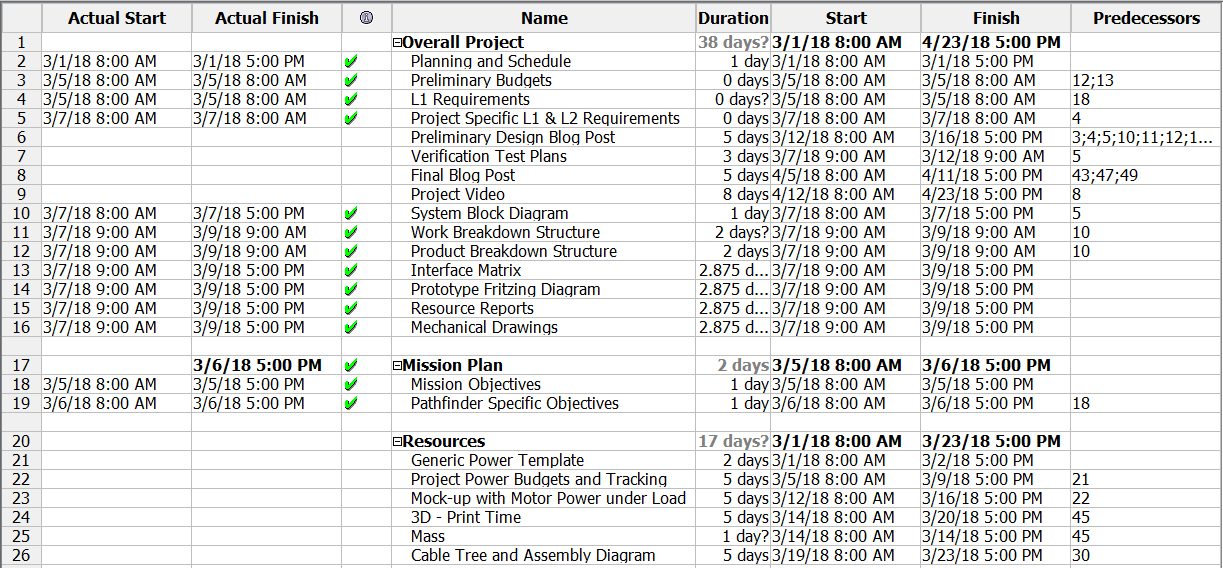
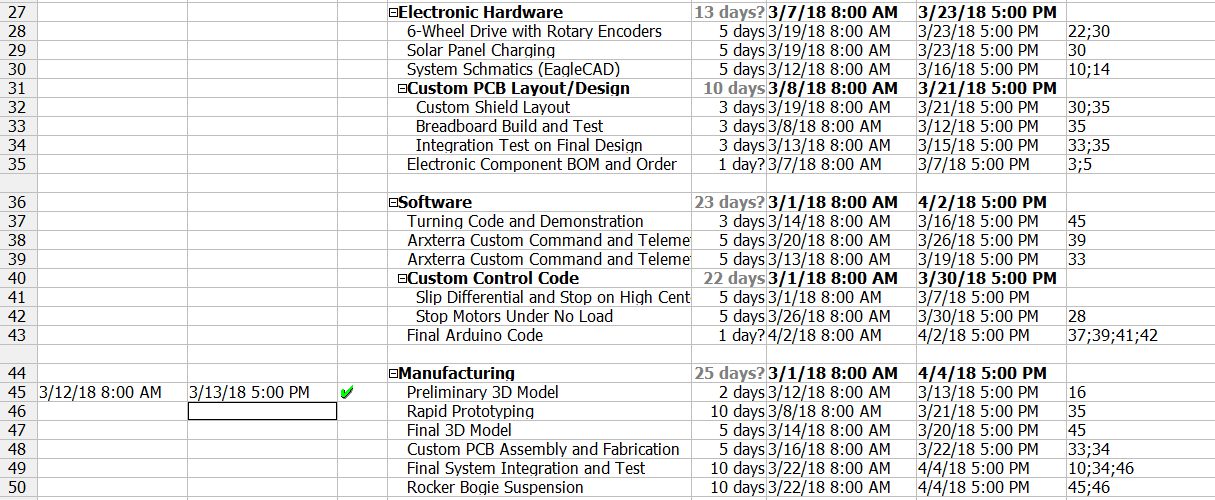
Figure 17: Schedule Part 1

Figure 18: Schedule Part 2

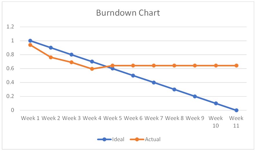
Figure 19: Burndown Chart
References
- https://www.arxterra.com/pathfinder-s17-preliminary-project-plan/
- https://www.arxterra.com/spring-2016-pathfinder-preliminary-design-documentation/
- https://www.arxterra.com/the-pathfinder-fall-2016/
- https://www.arxterra.com/spring-2016-pathfinder-system-block-diagram-interface-matrix/