By:
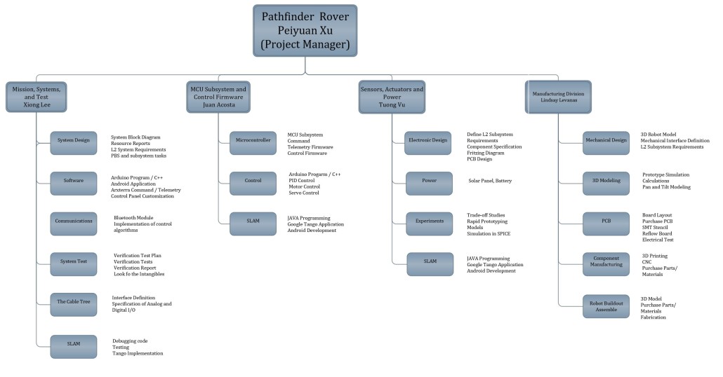
Peiyuan Xu (Project Manager)
Xiong Lee (Mission, System and Test Engineer)
Juan Acosta (MCU Subsystem and Control Firmware)
Tuong Vu (Sensors, Actuators and Power)
Lindsay Levanas (Design and Manufacturing)
Project Manager Research
Source Material
- Pathfinder Preliminary Documentation. 11/12/14 http://arxterra.com/wp-content/uploads/2014/11/Pathfinder-Preliminary-Documentation.pdf
- Pathfinder Final Documentation. 12/12/14 https://www.arxterra.com/pathfinder-final-documentation/
- Pathfinder Course Mapping. 10/30/14 https://www.arxterra.com/pathfinder-course-mapping/
- Pathfinder Final Video. 1/20/15 https://www.youtube.com/watch?v=p75FGE_HQl0
Review of Literature
Analysis of Past Level 1 Requirements
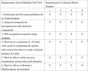
Requirement Evaluation Rubric:
- Is the requirement, Quantitative, Verifiable, and Realizable?
- Is the requirement response to customer’s expectations?
- Does the requirement move the design process forward?
- Does requirement provide links to source material?
Spring 2016 Discussion of Requirements from Fall 2014:
The Group clearly stated the issue that automation industry meets and the needs for them to develop autonomous and self-Sufficient machines. The project objective was generated properly based on the customer’s expectation. However, on the requirements level, the group did not use enough quantitative, verifiable, and realizable thinking to write their level 1 requirements. For number 5 and 6 of their requirements, there was no quantitative variables that can be measured or proved to meet their requirements. Those requirements could be improved by mentioning more details of the environment such as quantitative temperature, wind speed, dust level, etc. In addition, the word “shall” should be used instead of “must” in those two requirements. Some of the requirements are lack of source links for us to research them in details. Their preliminary research posted nearly at the end of the semester and included level 2 requirements as well. Their final documentation and preliminary research had very much the same content. Their final video documentation was made properly as it contains their design of work and testing activities. But one thing I noticed that for the video documentation, they did not include the final testing of Pathfinder running in the Mediterranean environment which was one of their requirements.
Spring 2016 New Project Objectives:
- Pathfinder should be able to explore the desert area for a whole day.
- Google Tango tablet will be used and installed onto the Pathfinder.
- Solar panels will be used to charge the batteries.
- Pathfinder allows to move certain amount of time and stops to wait for solar panels charging the battery and then continue exploring.
- Pathfinder should autonomously go to a destination by clicking a point on the photo that google tango captures.
- Make the Pathfinder cool
Spring 2016 New Level 1 Requirements:
Many changes will happens on the Pathfinder this semester. These include using solar panels to charge the batteries and also google Tango tablet will be used to navigate pathfinder instead of using GPS navigation/waypoints. Therefore our requirements will various from Fall 2014 semester. These may include:
- The pathfinder shall be able to handle the desert terrain. Meaning it will function properly for up to 100 degrees and has proper suspension system that can handle bumpy road condition.
- The pathfinder shall be self-sufficient by using solar panels.
- The pathfinder will explore the desert for at least 15 minutes and then it will recharge for up to 1 hour and repeat the steps for the rest of the day.
- Sealed environment for microprocessor, electronic components and Tango tablet
- An extra portable charger will be used to charge Tango tablet separately or an extra small panel will be used to do so.
- The weight of Pathfinder shall not exceed 17 pounds
Spring 2016 Preliminary Budget:
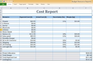
For our preliminary budget, we will assume to spend up to $150 on appropriate solar panels that have enough power to charge batteries in short amount of time. The Google Tango can be borrowed from the president form CSULB HKN society. Other mechanical parts and electronics can cost up to $150. Total cost will be limited to $300 negotiable.
Spring 2016 Discussion of Schedules:
- The final project will be due on May 9th (The Final Exam date).
http://web.csulb.edu/depts/enrollment/registration/final_exam/spring_chart.html
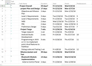
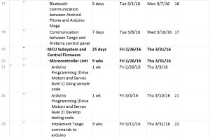
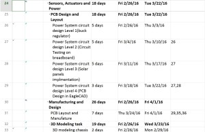
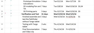
- It is important to break down project to small tasks and schedule the due dates for each task. The project breakdown structure will be done by system engineer and from that, due dates for each task will be determined and announced by project manager.
Systems Engineer Research
By Xiong Lee (Mission, System, Tests)
Source Material:
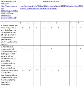
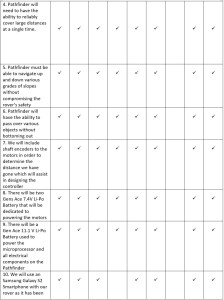
Level 2 Requirements from Fall 2014 semester:
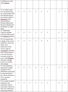
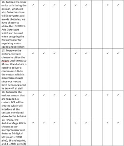
Summary of Level 2 Requirements:
Overall, their level 2 requirements were very good. They gave good documentations of what they did for their level two requirements. For example, how they designed their pan and tilt system for their android phone. There were things that could have been better documented. They didn’t list sources where they got the specs of their batteries, shield, arduino from.
Microprocessor and Arduino:
- Atmega 2560 microprocessor
- Arduino mega ADK
- Specs of the arduino
| Microcontroller |
ATmega2560 |
| Operating Voltage |
5V |
| Input Voltage (recommended) |
7-12V |
| Input Voltage (limits) |
6-20V |
| Digital I/O Pins |
54 (of which 15 provide PWM output) |
| Analog Input Pins |
16 |
| DC Current per I/O Pin |
40 mA |
| DC Current for 3.3V Pin |
50 mA |
| Flash Memory |
256 KB of which 8 KB used by bootloader |
| SRAM |
8 KB |
| EEPROM |
4 KB |
| Clock Speed |
16 MHz |
| USB Host Chip |
MAX3421E |
| Length |
101.52 mm |
| Width |
53.3 mm |
| Weight |
36 g |
Found on the website:
https://www.arduino.cc/en/Main/ArduinoBoardMegaADK
Some proposed level two requirements based on our level one requirement:
- A better electronic enclosure will be designed to keep the electronics protected (cooled).
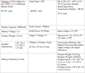
- The solar panel should be able to charge the two 7.4 volt batteries for the motor as well as the 11.1 volt system battery.
- There will be an enclosure for the tablet to protect it from the environment.
- There will be Bluetooth communication from the tablet and arduino.
Testing:
Their testing of their products can be found here. They tested their GPS, Communication Bluetooth, batteries, weight and height clearance and their coding. Most of these testing had good documentations of what they did in the experiment. One thing was where they got their sources material from. They didn’t show sources to how the battery should be tested or etc…
Flowcharts/System block diagram:
http://arxterra.com/pathfinder-axterra-gps-communication-part-three/
http://arxterra.com/pathfinder-code-flowcharts/
http://arxterra.com/pathfinder-arxterra-communication-commands/
http://arxterra.com/pathfinder-pin-interface/
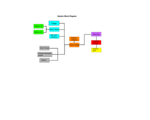
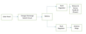
Their flowcharts and block diagrams were good. They specified everything they had on the pathfinder from their three batteries to the Bluetooth and GPS. For our system diagram, we’ll have to add the tablet and solar panel into the diagram. Our flowcharts will change because we have a different mission than what they have from the customer.
Interface System:
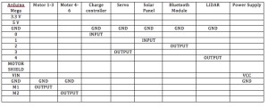
Their use of a separate pcb to store the sensors, regulators, Bluetooth, etc… (Shown above in the system block diagram) helped them make their electronics and wiring cleaner. Their diagram showed how each product interfaced with each other. On our project, we’ll have to make our Google Tango tablet communicate with the Arduino on the pathfinder. We’ll also have to use the arduino to communicate with the solar panel so it can charge up the batteries of the system and motors.
Electronics and Control Research
Sensors, Actuators and Power
By: Tuong Vu
E&C Division
Level 2 Sub-Requirements: (Based upon original level 2 requirements)
Servos :
- The servo must be able to support the weight of the Google Tango, which is about 82 lbs. (370 g). Google tango needs to be on the a rotating platform in order to navigate the pathfinder; therefore, the servo needs to have the capability of rotating 360 degree.
Motors :
- Generate enough torque to rotate the wheels in order for the chassis to move.
- Need to handle high current
- Protect these motors with a Buck regulator.
Battery.
- Battery needs to supply enough voltage and current to drive the motor.
- Keep stock battery.
- Ni-Lithium battery 10000ma at 5 volt for Google Tango.
Solar panel.
- The solar panel has to fit the pathfinder, and the weight of solar panel should be around 5 lbs. max. Need to be able to deliver enough current and voltage to charge the Google Tango and motors’ batteries.
Buck regulator.
- Batteries and motors protection, a simple buck converter can be used to step down the voltage. This is critical, over charging the battery and oversupply the motors lead to heat building up within the components.
Charge/ discharge voltage regulator
- Charge/ discharge voltage regulator disconnect or connect batteries from the solar panel at a certain voltage range. Pathfinder will have self-charge capability with this circuit installed.
Device Recommendations & Test Proposals:
Servos:
- We will be using the stock motor from the previous class. (This decision may change in the future)
- Test Servo to see if it can hold 5 lbs.
Motors:
- We will be using the stock motor from the pathfinder. Base on testing, our motor needs about 1.8 voltage and 1.6 amps to turn on.
- Test for the motor voltage and current required to turn under various load.
Solar Panel.
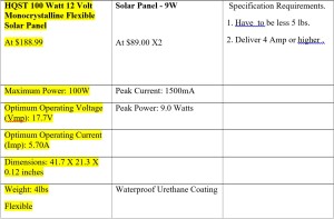
- Conduct solar panel test to find the average output voltage and current.
- Test charge/discharge circuit by using it to charge a 12-voltage 10A battery with the solar panel.
Buck regulator:
- The role of the buck is to lower the voltage from the solar panel to the motors, protecting them from shock or heat damage. The current motor on the path finder is about 1.8 voltage to turn on, so buck regulator needs to lover the voltage from the solar panel or battery down to 1.8 voltage. Texas Instrument, Digi-key, and Mouser Electronic have the Buck Regulator we need for our project. We can self-build the Buck Regulator circuit.
- We need to conduct some test to make sure the Buck Regulator can integrate with circuit.
Charge /discharge voltage regulator.
- We will have to design this circuit from the ground up. The idea is using a power P–Channel Depletion Mosfet as a switch to control the flow of current from the solar panel to the motors’ batteries and Google Tango Tablet.
- We need to build and test the design to make sure circuit can connect and disconnect the batteries from the solar panel.
Battery
- We are using batteries from the previously installed on the pathfinder.
- Test for the Maximum Voltage level of the batteries, in order to calibrate the voltage level that the “Charge /discharge voltage regulator” has to disconnect the batteries from the solar panel.
MCU Subsystem and Control Firmware
By: Juan Acosta
Source Material:
- Arxterra Website, Arduino
https://www.arxterra.com/rosco-and-pathfinder-arduino-code-versions-available/
- Arxterra Website, GitHub, Pathfinder_Rover
https://github.com/arxterra/Pathfinder_Rover
- Arxterra Website, Pathfinder, Pathfinder Final Documentation
http://arxterra.com/news-and-events/members/pathfinder-4/
Discussion based on previous Level 1 & 2 Requirements:
The previous design of the Pathfinder used modified Servos for pan and tilt control of the phone. Instead of modifying an existing servo, they should have bought an inexpensive servo with no limitations on turning radius to solve this minor issue. This could have saved a little time and helped moved the project along by allowing more time to focus in other areas that were having major issues.
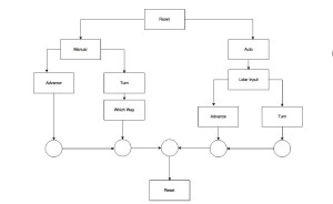
The main loop program flow for the previous Pathfinder project was successful in drawing out the tasks of the Pathfinder. They implemented simple true or false checks in order decide what action the Pathfinder should take next. This looks like a fast, simple and effective way of implementing the main loop program.
The previous design’s code flowcharts were a good starting point for their final software implementation. They clearly defined sensor input triggers and appropriate decisions based on those inputs. They did not mention if their decisions or actions were a result of Level1 requirements, but it looks like they carefully planned out all of the necessary decisions the Pathfinder would have to make based on the terrain and lap objectives.
Discussion based on New Level 1 & 2 Requirements:
For the MCU Subsystem and Control Firmware section of the Electronics & Control Division, I will have to: 1) write the firmware required to translate commands from the tango tablet into control signals to the motors and servos in order to move the Pathfinder or move the pan and tilt field of view for the Google Tango, 2) Read sensors such as wheel decoders and translate into data bytes for calculating speed and distance to travel, and 3) implement control algorithms for controlling the charging of the Pathfinder’s solar panel charging network.
In order to code for tasks 1 and 2, I will reference and then modify the Pathfinder Code Flowcharts created by a past semester’s blog posting. I will also reference previously uploaded code for the Pathfinder that is available on GitHub from the Arxterra website.
Lastly, in order to code the algorithms for measuring and controlling the charge of the battery via solar panels, I will have to do further research on safe charging procedures and requirements and battery protection. I hope to have a scaled version of the Pathfinder available for prototyping and testing of the control firmware before final implementation to the final design.
Based on previous code for the Pathfinder, some of the level 2 requirements will have to be modified or deleted. For Example, our design will incorporate the Google Tango so there will be no need for obstacle avoidance measures and sensors since our design won’t be autonomous as it was defined as a level 1 requirement that the Google Tango is to act as a remote control with field of view. Examples of some of the code that I will have to tailor to our design are the programs written to measure battery consumption, drive the motors, and drive the servos. Programs that I might have to develop are charge controlling algorithms to safely charge and discharge the Pathfinder’s battery cells for optimal usage as define by the level 1 requirement needing the Pathfinder to be able to spend a day exploring the Amboy Crater.
A few of the programs previously written for the Pathfinder have not been uploaded or tested, so it will be crucial for me to start testing and debugging algorithms that are available on GitHub to determine which ones are viable and which ones I will need to code myself. It will be important for me to have working knowledge of how to code and upload programs onto the Arduino Board, so I will attend any and every training session that the Electronics & Control Division Manager hosts in order to continue to move this project forward. The Previous Design utilized an Arduino Mega so I will have to research on similarities and differences between the Uno and the Mega and see which one would be a better level 2 requirement solution.
Design and Manufacturing Research Work
By: Lindsay Levanas
Source Material
- Pathfinder Preliminary Project Documentation, Project Requirements 1. Sealed pan and tilt camera platform for an Android phone, pg. 3-4, 11/12/14 http://arxterra.com/pathfinder-preliminary-project-documentation/
- Pathfinder Preliminary Project Documentation, Project Requirements 2. Sealed environment for microprocessor and electronic components, pg. 4, 11/12/14 http://arxterra.com/pathfinder-preliminary-project-documentation/
- Pathfinder Preliminary Project Documentation, Project Requirements 5. Must be able to safely traverse mountainous terrain and avoid obstacles, pg. 5, 11/12/14http://arxterra.com/pathfinder-preliminary-project-documentation/
- Pathfinder Pan and Tilt Camera Platform, Theory, 10/26/14 http://arxterra.com/pathfinder-pan-and-tilt-camera-platform/
- Pathfinder Pan and Tilt Camera Platform, Procedure, 10/26/14 http://arxterra.com/pathfinder-pan-and-tilt-camera-platform/
- Pathfinder Preliminary Project Documentation, Major Project Elements 1. Sealed pan and tilt camera platform for an Android phone, pg. 7-8, 11/12/14 http://arxterra.com/pathfinder-preliminary-project-documentation/
- Pathfinder Preliminary Design, 11/12/14 http://arxterra.com/pathfinder-preliminary-design/
- Pathfinder Preliminary Project Documentation, Major Project Elements 2. Sealed environment for microprocessor and electronic components, pg. 8, 11/12/14http://arxterra.com/pathfinder-preliminary-project-documentation/
- Pathfinder 3D Printing, Introduction, 12/11/14 http://arxterra.com/pathfinder-3d-printing/
- Pathfinder Custom PCB Design, Background, 11/11/14http://arxterra.com/pathfinder-custom-pcb-design/
- Pathfinder Preliminary Project Documentation, Major Project Elements 5. Must be able to safely traverse mountainous terrain and avoid obstacles, pg. 10, 11/12/14http://arxterra.com/pathfinder-preliminary-project-documentation/
- Pathfinder Custom PCB Design, Schematic Components, 11/11/14 http://arxterra.com/pathfinder-custom-pcb-design/
Introduction
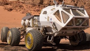
During the fall of 2014, the first Arxterra Pathfinder project was outlined and implemented. The basic concept was to mirror Mars rovers, both in their basic construction and autonomous ability. To this end, requirements were created to help guide the original designers in building a simplified Earth base model. Now, during the spring of 2016, a new group of engineers will work together to build upon the previous Arxterra Pathfinder project to bring it closer to the rovers that have been sent to Mars. Following below is a review centered on the design and manufacturing elements of Pathfinder’s requirements as discussed in its original documentation. The review will consist of the evaluation and modification of previous requirements to encompass the new project goals to implement Google Tango and solar panels in the current Pathfinder model, as well as new requirements where necessary.
Review of Pathfinder’s 3D simulated sealed pan and tilt camera platform for an Android phone requirement
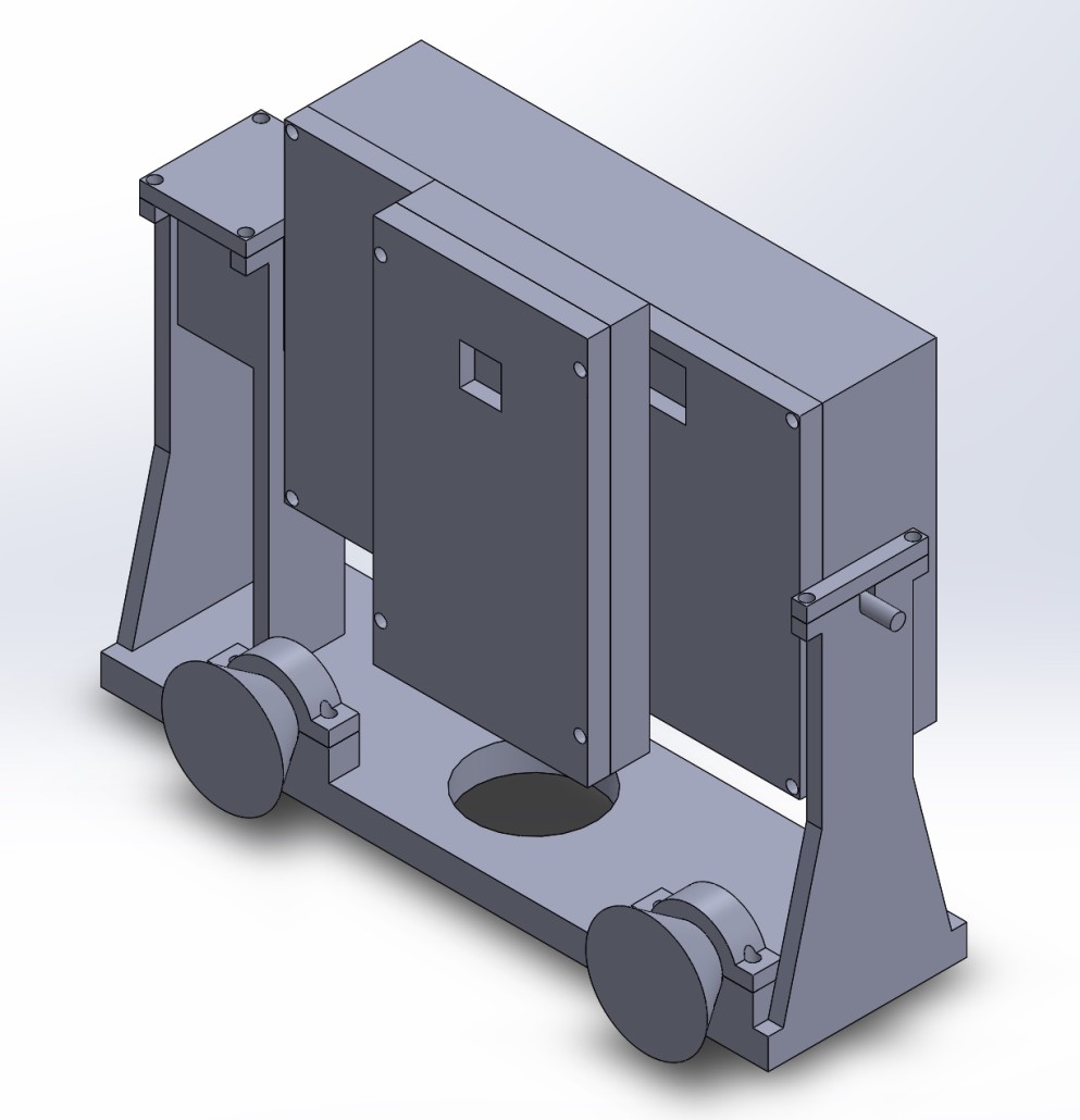
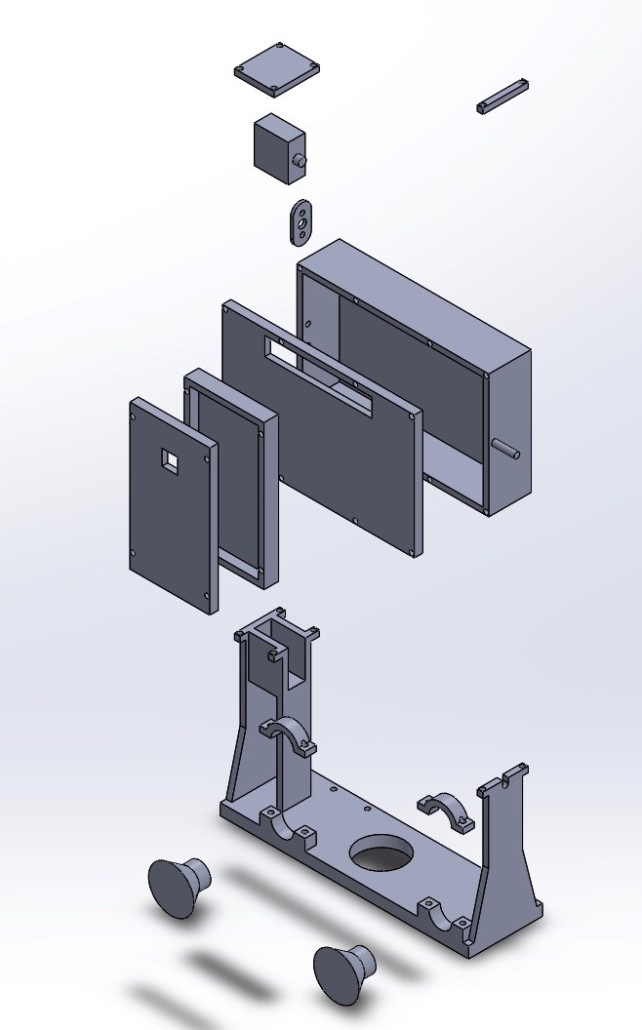
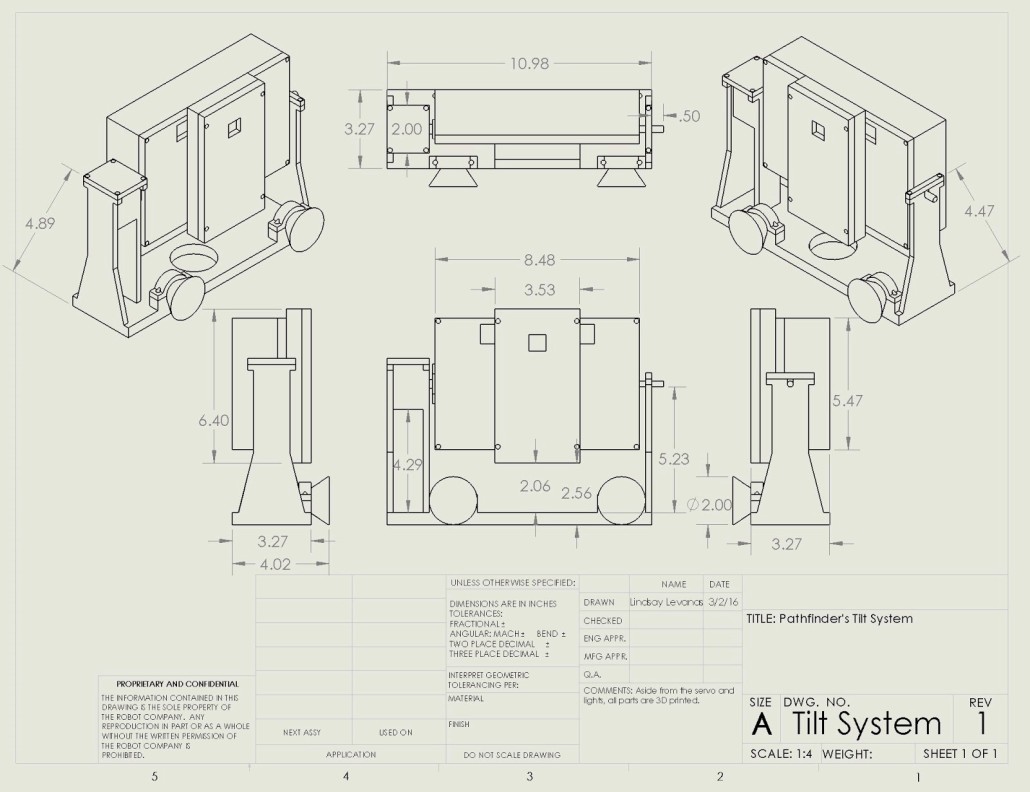
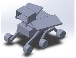
Pathfinder’s first original requirement was to utilize a sealed pan and tilt camera platform for an Android phone.1 Using the dimensions of the Pathfinder’s base and the field of view measurement calculations from the Android phone’s camera, a design was selected and modeled.5 While the measurement requirements are quantitative, verifiable and realizable, the resulting 3D model of the pan and tilt platform is not, as not all measurement dimensions are given. The dimension of each piece is not defined, and so a working 3D model of this platform cannot be duplicated. Located at the subsystem level (level 2), this 3D modeling requirement is linked to the project level (level 1) requirement for a sealed pan and tilt camera platform for an Android phone.6 With the proper measurements, this 3D model would move the design process forward, as materials for the parts could then be selected (by trade-off study, though this process is currently missing from Pathfinder’s documentation) and the final product could be constructed on Pathfinder’s base.
For the spring 2016 Pathfinder project, the above requirement and it’s subsequent requirements, trade-off studies, and measurement calculation process will not change much accept to accommodate a Google Tango tablet as the camera, instead of an Android phone. Also, as the 3D model of the pan and tilt platform is not clearly defined, a trade-off study of different designs and their measurements will be done.
Lastly, a new sublevel requirement will be added to account for temperature control of the sealed pan and tilt platform.
Review of Pathfinder’s 3D simulated preliminary design requirement
Another of Pathfinder’s project level (level 1) requirements was to create a sealed environment for the microprocessor and electronic components.2 Therefore a subsystem (level 2) requirement to 3D model the sealed environment was created.8 However, unlike the pan and tilt platform, the sealed environment for the electronics wasn’t modeled alone. Instead, both sealed environments were 3D modeled together with the body of Pathfinder to create the preliminary design requirement.7 As this design features 3D modeled pictures only, it is qualitative and not verifiable or realizable. Also, while the 3D modeled sealed environment for the electronics is linked to one of the project requirements, the Pathfinder 3D model as a whole is not. Therefore, it should be worded such that it encompasses the other two sealed environment requirements and should replace them as a project level (level 1) requirement. The sealed pan and tilt camera platform for an Android phone requirement, and the sealed environment for the microprocessor and electronic components requirement should then be redefined as subsystem (level 2) requirements so that the link back to the project level (level 1) requirements is easily traceable. Placed in this order, the preliminary design requirement would move the design forward, as then the subsystem requirements for the sealed environments would naturally follow. Finally, note that there are no links to source material and that no equations are used to calculate the initial set up for the preliminary design requirement.7
Similar to the 3D simulated sealed pan and tilt camera platform for an Android phone requirement, the 3D simulated preliminary design requirement is lacking in measurements and design trade-off studies. However, as the spring 2016 Pathfinder project will incorporate a Google Tango tablet and solar panels in its design, different structural trade-off studies then those mentioned to be missing will be conducted to account for the new design conditions.
Lastly, a new sublevel requirement will be added to account for temperature control of the sealed environment for the microprocessor and electronic components.
Review of Pathfinder’s 3D printer requirement
Based on the original documentation, the 3D printing of the sealed pan and tilt camera platform for an Android phone is a subsystem (level 2) requirement.9 As measurements are not given, the 3D printer requirement is qualitative only, and not verifiable or realizable. Had this requirement been listed under the project level (level 1) requirement of making the sealed pan and tilt camera platform for an Android phone, it would have been a subsystem (level 2) requirement, but it was not. 3D printing was however mentioned under the project level (level 1) requirement to make a sealed environment for the microprocessor and electronic components,8 but then there is no documentation on that manufacturing process. Both of the project level (level 1) requirements mentioned should contain 3D printing as a subsystem (level 2) requirement to help link the two levels together. No links to source material are mentioned, though one about the quality expectations of 3D printers would help. Such a source would allow for a more realistic and detailed requirement. Providing the quality of the 3D printed sealed pan and tilt camera platform for an Android phone is high, this requirement moves the design forward in that it may now be integrated onto the body of Pathfinder. Also, although none are mentioned, this requirement is based on the 3D simulation’s measurements and dimensions.
Review of Pathfinder’s Custom PCB Design requirement
As there is a project level (level 1) requirement for Pathfinder to safely traverse mountainous terrain and avoid obstacles, it follows that there is a subsystem (level 2) custom PCB Design to limit the amount of wires in the open.10, 11 Though a qualitative requirement, it is still both verifiable and realizable. No links to source material is listed, however there is both a picture and pin assignment chart included in the document, making it possible to replicate and verify the PCB design requirement.12 Slimming the electronic components on to a PCB moves the design forward to meet its project (level 1) requirement of safely traversing mountainous terrain and avoiding obstacles.3
For the spring 2016 Pathfinder project Google Tango will be used instead of the Android phone’s camera, GPS system, and sensors. In addition, Solar panels will be used to charge the batteries, therefore powering Pathfinder’s system. Both of these features will be implemented into the PCB while their previous counterparts are removed. As such, a different PCB board will be used based off of the new schematic that the electronics and control engineer (PCB Design) will design.
Conclusion
Pathfinder’s design and manufacturing will include 3D simulated models of Pathfinder as a whole, of the sealed pan and tilt camera platform for a Google Tango tablet, and of the sealed environment for the microprocessor and electronic components. From these models, parts may be either 3D printed or purchased. Finally, a custom PCB run by solar panels will be assembled.
Creativity Exercise:
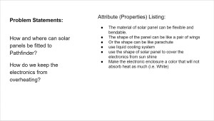
Problem Statements:
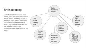
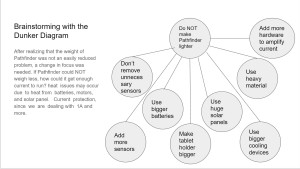
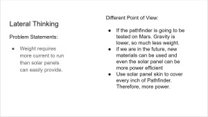
- Weight requires more current to run than solar panels can easily provide.
- Runs on batteries, not solar panels. How and where can solar panels be fitted to Pathfinder?
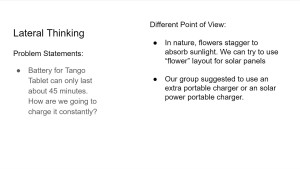
- Battery for Tango Tablet can only last about 45 minutes. How are we going to charge it constantly?
- Cooling system for electronics. How do we keep the electronics from overheating?
