Biped Movement Codes

By Kevin Huynh, Project Manager / Computer Systems and Software

Objective:
This blog will focus on the ideas behind how the code from projectbiped and the code from Spring 2014 handle the animation playback for walking and turning. It will also go into the reason for the switch.

ProjectBiped Code :
The most recent code can be found here:
http://www.projectbiped.com/prototypes/rofi/programs/arduino-action-playback

The code on project biped uses a timing system for the playback of the robot’s walking animation. The Action class holds all of the code for this movement method.

Update

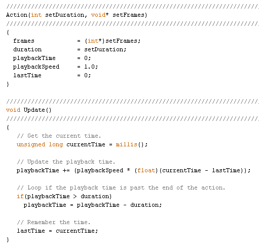
The timing system starts with the function Update, which calculates playbackTime with the variables currentTime, lastTime, playbackSpeed, and duration. The currentTime variable is determined by the Arduino command millis() which returns the number of milliseconds since the microcontroller began running the program. The lastTime variable is equal to the previous currentTime value from the last time the walking animation frame was updated.

The playbackSpeed is determined by the user, based on the speed they chose when creating action frames with in RobotPoser. The calculation value is assigned to a variable called playbackTime, which is used in the function GetCurrentFrame to get the frame the robot should be on. If the calculation for playbackTime resulted in a value greater than the duration, the duration value is subtracted from the playbackTime, to create the animation loop.

Actions

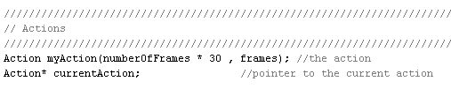
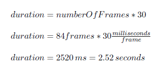
In the most recent code, the duration of the action is determined by the numberOfFrames variable multiplied by 30, but in the code exported from RobotPoser, it is multiplied by 20. ~I’m not exactly sure what those numbers are, but they are likely values for milliseconds per frame. This would result in a time value. For the most recent code, the duration would be 2.52 seconds for the entire walking animation.

durationCalculation

GetCurrentFrame

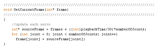
Once playbackTime and duration are calculated, they are used in the GetCurrentFrame function. The parameter passed into GetCurrentFrame is a blank 1×12 array for containing the animation frame the robot will move to. The pointer sourceFrame points to the address of the frames array plus a value based on the playbackTime and numberOfJoints. From that address, the frame array takes 12 (numberOfJoints) from the frames array and the robot is told to move the servos to the specified positions.

Example:
When the robot starts up, the there is lastTime is set to 0. Suppose the value retrieved from the millis() command is 1000 ms, so currentTime = 1000 ms. The playback time is then equal to 1000 ms. Since the playbackTime is less than the duration of 2520 ms, there is no subtraction.

Then the GetCurrentFrame function is called and an empty 1×12 array named frame is passed into the function. From the equation, sourceFrame is equal to the address of the frames array + ((int)1000/30)*12. Since 1000/30 is type-casted to an integer type, the value is rounded down to 33, so sourceFrame = (address of the frames array) + 396. This points to the address of the first value of the 33th (if the first row is counted as the 0th row) frame of animation. Afterward, there is a for loop that loops 12 times to get all 12 values of the 33th row to put into the frame array for use in the SetServoPositions function. The frame array at 1 second should be:
{382, 70, -2837, 420, 4275, 1102, -1770, -472, 972, 0, -1520, -2612 }

Spring 2014 Code:
PlayFrames
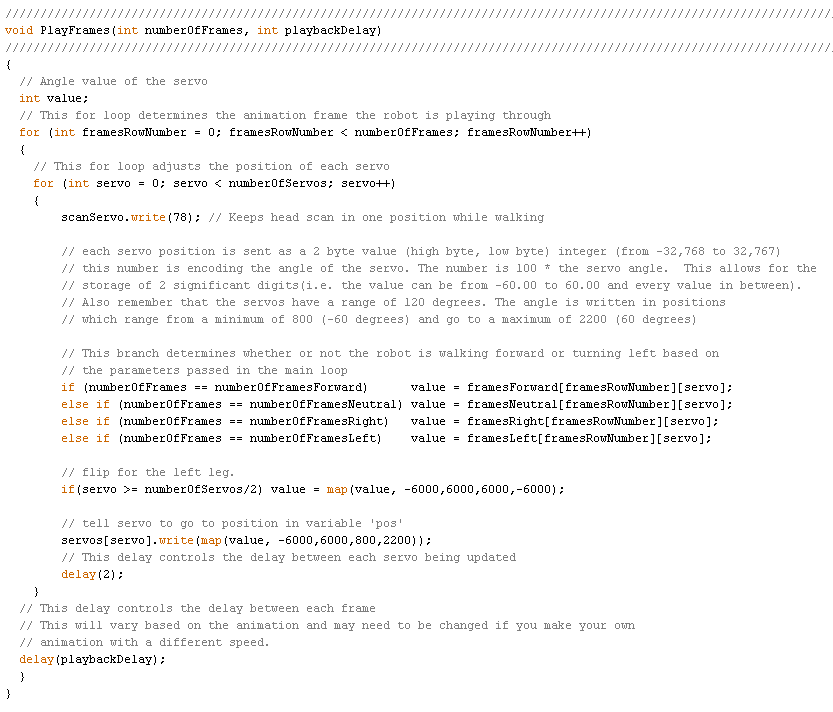
The code used for Spring 2014 used a simpler method for playing the action frames. Rather than use a timing system to determine which frame the robot should be on, the new code uses two loops to run through every element of the action frame array. One loop runs through the elements of each row to update each servo. The second loop moves from row to row to progress the animation. A playbackDelay variable is used to determine the speed of the action progression. The action of moving the servos to their positions is based on the SetServoPositions function from the original code. The rest of the code is similar to the original code.

Reason for the switch:
When creating the animations and testing them out on RobotPoser, there were no significant issues with the playback. However, when attempting to have the microcontroller handle the animation in a standalone code, the robot would start on a frame in the middle of the walking animation, rather than start on the first frame.

This issue became more prominent as more code was added to handle the obstacle avoidance using the ultrasonic sensor, since the delays caused by the use of the ultrasonic sensor affected the timing of the animation. The problem was found when two things happened. The first was that the incorrect leg oved forward at the start of the playback. The second was the effect of the addition of the ultrasonic sensor code and the right turn code on the forward walk layback. After the robot turned right in response to an object 30 cm in front of it, the forward walk would start on the incorrect frame.

With the new program, the robot will always start on the first frame and run through the animation without skipping a frame. The addition of more code has been simplified because of the minimal impact on the animation playbacks, since the playback speed is controlled by a manual delay. In addition, the new code will hopefully be easier to understand at first glance.

Main Code (without Arxterra):
https://github.com/kh0/Spring-2014-ROFIA/blob/master/ROFIACode/MovementCode

Note: The Arduino code exported from RobotPoser does not include the functions that apply the calibrations to the frames of animation.

Completed schedule and test plans

By Mason Nguyen, Project Manager

In order to build a successful project, it is important that our team to develop an effective test plans and schedule to manage our assignments. Our test plans will be divided into four categories where each member is expected to perform and complete.

3D Model:

A hexapod model will be designed through our manufacturer Vinh Kim. He will be using Solid Works program to perform stress test, materials test and create initial 3D design for our hexapod.  The timeline to complete his assignment is 7 weeks. Down below is Vinh’s roadmap break down.

3D Modeling: 1.5 Weeks

  • Designing the Hexapod body, femur, tibia, and bracket using SolidWorks.
  • Creating a prototype model of the Hexapod using cardboard, cable ties and tape.

 Solid works and materials testing: 3.5 Weeks

  • Doing a trade-off studies using Silicone Rubber vs. Urethane Rubber.
  • Measuring the component and calculating the weight distribution.
  • Using SolidWorks Simulation Xpress Study to test the materials and perform a stress test on the tibia and bracket.

 Manufacturing: 2 Weeks

  • 3D printing the Hexapod body parts.
  • Molding the Hexapod body parts out of rubber.
  • Casting the Hexapod parts using Urethane.
  • Assembling the Hexapod.

 Power:

To support the hexapod movements, servos will serve as the primary pillar for the hexapod to walk. Meanwhile, the battery will be the main component to power up the hexapod. To understand more about servos, several testing experiments will be conducted to test its functionality such as angle, rotation, current and torque.  This assignment will be performed by the project manager and it will take 10 weeks to complete. Also components will be ordering based on the trade-off study from the servos and battery.

Servo testing and requirements: 3.5 Weeks

  • Comparing servos (price , size and power)
  • Trade-off study of servos
  • Testing servos torque, angle and current drawn

Battery testing and requirements: 2.5 Weeks

  • Comparing batteries (price, size and power)
  • Testing power allocation of battery.

Ordering Supplies: 4 Weeks

Programming:

Programming will be the most difficult task due to many requirements of the servos angle and rotation. To complete this assignment, our team computer engineer Chau To will be given 10.2 weeks to run various tests and calculations.  His roadmap is defined below.

Servo calibration testing: 2.5 Weeks

  • Matching the angle swing of each servo in degrees (from 0 to 180 degrees).
  • Calculate the delay time and servo’s angle for Hexapod movement.

Software testing: 8 Weeks

  • Writing code for Hexapod movement including WALK, RESERVE, TURN LEFT, TURN RIGHT, PHONE CAMERA CONTROL functions.
  • Implement and Trouble shooting.
  • Link to Artexia Android Apps. 
  • Troubleshooting for entire system.

Communication:

Using an android phone, the hexapod will be controlled wirelessly from Arxterra interface. Tien Dang who’s our communication engineer will be responsible to perform the Arxterra coding and testing integration. His assignment is expected to complete within 8 weeks. He also will be helping out Tommy with Arxterra interface. His road map is defined below:

Arxterra testing requirements: 4 Weeks

  • Learning about Arxterra new version of Arxterra. 
  • Installing the app on the Android phone.

Arxterra coding: 4 Weeks

  • Testing Arxterra code.
  • Arxterra phone compatability test.
  • Linking Arxterra web page from laptop to the android.

figure 1

As shown in the schedule, the team has performed and completed all of our tasks. Our final finishing touch will be demoing process and a short movie clip to wrap up our project. 

Hexapod System Diagram

 By Chau To

This blog post contains the system block diagram, fritzing schematic diagram, breadboard diagram, and a bonus MATLAB code for angle calculation of the Hexapod movement.

Hexapod system block diagram:

figure 1Fritzing schematic diagram:

Hexapod connected servo directly from Arduino ADK Digital I/O pins.

figure 2

 Fritzing Breadboard Diagram:

The digital pins we used are pin 30 to 47 for leg servos. Pin 26 for Camera servo.

figure 3

The protection circuit such as:

BONUS:

This is the bonus MATLAB code for my “angle calculation” blog post (available at: https://www.arxterra.com/hexapod-forward-and-backward-movement-calculation-and-algorithm/)

This code calculated the angle where the shoulder, femur, tibia have to make and compensate with each other so that the hexapod can move forward or backward steadily.

Please read the link for blog post provided above to understand the input and output parameters of this function:

function [new_a,del_a,new_b,del_b] = cal_ang( T,F,alpha,beta,theta )
%Inputs parameters: T, F, alpha, beta, theta
%T = length of Tibia
%F = length of Femur
%alpha = inital angle of Tibia
%beta = inital angle of Femur
%theta = inital angle of shoudler

%Outputs:
%The New and the adjustment angle for alpha
%The New and the adjustment angle for beta
A = T*sind(alpha)+ F*cosd(beta);
x = A – A*cosd(theta);
new_a = asind((T*sind(alpha)+x)/T);
del_a = new_a – alpha;
y = T*cosd(alpha)-T*cosd(new_a);
new_b = asind((F*sind(beta)-y)/F);
del_b = beta – new_b;
fprintf(‘The new alpha is: %.2f\n’,new_a)
fprintf(‘The adjust in alpha is: %.2f\n’,del_a)
fprintf(‘The new beta is: %.2f\n’,new_b)
fprintf(‘The adjust in beta is: %.2f\n’,del_b)

Initial Code Implementation

By Matthew Clegg – Computer & Control Systems

With the assembly of Spiderbot about 80% complete, implementation of the code for its operation is finally being implemented. There have been many difficulties in Spiderbot’s operation. After several runs of the code, it seems Spiderbot is having difficulties with keeping its base off the ground. At this moment there is hope that this issue can be fixed with code, or that maybe there is not enough traction on the surface on which it is being tested.

A video of the first steps of the nearly-completely-assembled Spiderbot can be seen at the following link:

http://youtu.be/brh-NxkkgS8 

Spiderbot Assembly

By Simon Abatay – 3D Modeling & Manufacturing

With the final parts obtained from manufacturer Ali Etezadkhah and the final components casted and cured, the body of Spiderbot was ready for painting. After all the parts were primed and painted, the final Spiderbot was assembled. The servos for the femur pieces had to be taken apart initially in order to place them securely into their designated holders. A combination of epoxy and small screws was used in order to hold the tibia pieces in place with the brackets connected to the femur pieces. Some components were held together with Velcro and double-sided tape until the final operational components could be placed into Spiderbot.

Below are images of the assembly of Spiderbot without the operational components and pan and tilt components.

 SONY DSC

SONY DSC

SONY DSC

SONY DSC 

SONY DSC


Modified Slush Casting Method

 By Simon Abatay – 3D Modeling & Manufacturing

After the mold is finished, it is time to cast the leg.

This method is a variation of roto-casting and is popular in the DIY prop making community.

(TheRPF)

http://www.therpf.com/f11/mold-making-slush-casting-whre-do-i-start-36457/

Materials:

  • 2-Piece mold
  • Smooth Cast 300 Part A and B
  • Rubber bands
  • Oil Based Clay
  • Liquid Dye
  • Plastic Cups
  • Mixing device

Process:

  1. Use rubber bands to hold the 2 piece mold together. Apply the rubber bands in both the horizontal and vertical direction of the mold.

    SONY DSC

  2. Pour equal amounts of the Smooth Cast 300 parts in 2 separate cups. Roughly about 2 – 3 ounces per.
  3. Pour both parts into the same plastic cup and stir well.
  4. Check both the color and viscosity of the mixture to make sure it is uniform throughout.
  5. Drop about 3 eye drops of liquid dye into the mixture and repeat step 4 after mixing.
  6. Pour the mixture into the mold.
  7. Lift the mold and move it side to side and in a circular motion. This will slush the mixture around so it will form along the sides of the mold.
  8. After about 2 minutes of casting you will see that the mixture will bubble. This bubbling is due to the dye and resin mixture.
  9. The mixture will then rise out of the mold where it was initially poured into.
  10. Using the clay, plug the hole so that the bubbling mixture doesn’t rise past the mold itself. This bubbling effect will fill the inside of the mold while keeping the desired shape and look.
  11. After 15 Minutes, Pull the mold apart. What you are left with is a lighter version of the 3-D printed piece. The inside of the casted piece will mimic the honey comb effect of the 3-D part.

    Blog16_image2
    Blog16_image3

  12. Sand, prime, and paint to the desired color scheme, or keep it raw.

Blog16_image4

The following link is the process in video form:

https://www.youtube.com/watch?v=I57pOEQ6x_w&feature=youtu.be

Solutions to Wi-Fi connection issue

Members:
Vinh Khoa Ton: Biped team, Control & Image Processing
Tien Dang: Hexapod, Communication

Chau To: Hexapod, Computer systems & Software
Mevan Fernando: 3D Bio Printer, Sensors, Actuators & Powertrain
Robert Licari: Communication

Objective by Vinh Khoa Ton:

Hexapod team and Spiderbot team need to run their robots on a track field that does not support internet connection. Our team’s goal is to find a way for them to get access to the Wi-Fi connection so they could control their robots remotely using Arxterra control panel. The solution should have minimum cost. The internet connection should be stable (no disconnection or lost signal) with enough bandwidth for at least two mobile phones and two laptops, and the range of Wi-Fi is enough to cover the track field.

Some considered solutions

Wi-Fi Antenna by Tien Dang

http://arxterra.com/wifi-antenna/

Wi-Fi Range Extender by Chau To

http://arxterra.com/wi-fi-range-extender/

Buy a Wi-Fi/4G access point by Vinh Khoa Ton

http://arxterra.com/buy-a-wi-fi4g-access-point/

Main solution – Smart Phone Hotspot by Mevan Fernando and Robert Licari

http://arxterra.com/smart-phone-hotspot/

Conclusion by Robert Licari

In simplest words, the best and easiest WLAN (Wireless Local Area Network) that can be produced in our testing grounds is the smartphone hotspot capability that is virtually a company standard. In an area that demands the use of a Wi-Fi connection in this manner, we have verified that this solution covers our requirements of speed, cost, bandwidth, and range.


Wi-Fi Range Extender

By Chau To

Introduction:

Wi-Fi extender or Wi-Fi booster is a device that picks up a wireless signal and then rebroadcasts that signal. It acts as a second access point for other devices to connect to. The range of a typical Wi-Fi extender is around 300ft. Some expensive Wi-Fi boosters can achieve a range of around 450ft.

Pros and Cons:

Pros:

1. The Wi-Fi extender can be a solution to solve the Wi-Fi problem at the testing point. It can be used as a second access point between the building and the test place.

2. It is very easy to set up. There are 3 steps to set up a Wi-Fi extender. First, connect to the laptop via DSL cable. Second, launch the set-up GUI. Third choose the wi-fi signal to extend.

3. It is easy to find: Fry’s, Best Buy, online etc.

4. Quality and cost can be reviewed at this website:

http://wi-fi-booster-review.toptenreviews.com/

Cons:

1. The Wi-Fi extender always experiences 20%-50% throughput loss (the data rate loss) because it has to receive and then transmit data. As a result, the efficiency of the Wi-Fi extender is not that good. The amount of data used by Arterxa is very large because of the camera video streaming, so the efficiency of the Wi-Fi extender would affect the performance of the robot.

2. Wi-Fi extender is not very reliable. The connection is very bad especially for outdoor because of interference.

3. High-quality Wi-Fi extender can be expensive.

Testing:

Use the Diamond WR300NR Wi-Fi Extender (in the figure) to see if it can solve the Wi-Fi problem. At the test site, we experienced many problems:

1. The Wi-Fi extender used the school’s Wi-Fi signal beachnet+ and boost that signal over the parking to the test site. The best place to place the Wi-Fi extender is around 50ft outside of the building so that it could performed at max efficiency. However, the test site and the building is 500ft apart, the Wi-Fi extender couldn’t boost the Wi-Fi signal to the test area.

2. Interference is another major problem. Although the smart phone we used to connect to Wi-Fi was in the range covered by the Wi-Fi extender, the speed was very slow. And it lost connection all the time.

3. Power could be a problem because the Wi-Fi extender connected to 120V AC power from the wall, so we had to use a long cable to connect from the building to the parking lot.

Conclusion:

The Wi-Fi extender is not a good solution for the WIFI problem because of the range and the outdoor interference. A better quality and more expensive


Smart Phone Hotspot

By Mevan Fernando and Robert Licari

Introduction by Mevan Fernando

Tethering is when a smartphone is turned into a mobile Wi-Fi hotspot and its 3G/4G data connection is shared. Once tethering is turned on in the smartphone, any device with a wireless connection can connect to the internet via the smartphone’s connection.

Procedure by Mevan Fernando

The steps taken to connect to the Wi-Fi hotspot and connection to the Arxterra Control Panel on the mobile data connection is shown below. The mobile phone used was a Samsung Galaxy S3 and the test was run at the site of the route where the robot will navigate. The following set up tutorial is performed with an android phone (Samsung Galaxy S3).

Step 1 – Click on the Mobile Hotspot app on the phone
step1

Step 2 – Turn on Mobile Hotspot
step2

Step 3 – Connect to the mobile data connection using any device with wireless connectivity (password required)
step3

Step 4 – Log in to the Arxterra Control Panel
step4

Step 5 – Start control your robot
step5

Discussion by Robert Licari

Wireless provider

The wireless provider is a simple matter considering that most, if not all, of our employees carry a cellular phone and an almost equivalent number of employees carry smartphones. Taking this into consideration, we can simply utilize the sources provided by different service providers to view their coverage maps; however, they lay claim to all areas around long beach as a part of their “Nationwide Coverage” slogans dictate. To get a more accurate map, utilizing www.sensorly.com (a free coverage map source) we can see that Long Beach is not completely covered by any of the major providers. Sensorly, however, is a user-dependent tool and is thus, not 100% accurate either, but it does provide us with an idea of actual users, in the field, using data at varying speeds from 4G down to 2G (which are relevant for our purposes). Overall, this will not be an issue considering that the field is nearby one of the many sensorly tested areas, which we can safely assume and test for signal strength and viability.

Bandwidth and Range

Our major concern is Bandwidth and Range when we consider our service provider. This factor is almost completely dictated by the amount of customers utilizing bandwidth as well as the distance the client (in this case a laptop) is from the smartphone. This is reliant also upon the service coverage area that we are working in. To be clear the International Telecommunication Union has NOT set a defined standard for the rates of mobile data services. Upon further research, one can find multitudes of numbers with even more multitudes of tests done in controlled or uncontrolled environments. The reason for this is that it is highly dependent upon the above factors and is greatly influenced by movement of the hotspot. Generally speaking, it is widely accepted that we shall be receiving approximately 300 kb/sec. To be blunt, this number is not random, but in a world where some receive 25 Mb/sec and others that receive 25 kb/sec, it is difficult to accurately pinpoint an exact number for any particular time of day. On average, 300 kb/sec will be our acceptable bandwidth, which will begin to deteriorate as we begin to venture farther and farther from our client to a maximum distance of around 50 feet.

Cost

The final concern that we have will be cost, which is, quite possibly, the most varied of our concerns because this is strictly on a case-by-case basis. One person could have an unlimited data plan, while others could have a fixed data download plan that will limit them for the experiment. For this reason, should this be the final factor in deciding whether or not this is our solution, it is simply a matter of finding a volunteer with unlimited data to have their cellular phone be a mobile hotspot.


Buy a Wi-Fi/4G access point

by Vinh Khoa Ton

Introduction

A Wi-Fi/4G access point is a location that provides users wireless network. Nowadays, most electronic devices are equipped with a wireless adapter (mobile phone, laptop, tablet, watch, etc.), the demand for wireless connection increases rapidly. The Wi-Fi hotspot could be found usually in public areas such as airports, post offices, coffee shops, or fast food restaurants while the 4G hotspot could be found almost everywhere you go. The 4G access point is a portable device that give you Wi-Fi access.

Cost and Range

Wi-Fi hotspot is quite affordable offered by most major network carriers. AT&T offered Wi-Fi on the spot with $3.99 to $7.99 per session. However, Wi-Fi hotspot is limited only to public areas that offer the service. The track field that we need to have Wi-Fi access does not have a Wi-Fi hotspot nearby.

4G hotspot (or mobile hotspot) has more coverage range and gives more flexibility for outdoor internet usage such as hiking, camping, biking at some remote areas. A hotspot device usually works well within 50 feet and could support up to 5 users at the same time.

For example, FreedomPop offers 500 MB of 4G data free every month and charge $0.02 for every extra MB used.

freedompop plan

However, the drawback is that cost for the portable hardware is expensive, ranging from $50 and up to more than $100.

freedompop price

Conclusion

The Wi-Fi hotspot provides a pay-as-you-go option that suits our need for a short project demonstration but lacks the flexibility in coverage range. The 4G hotspot could provide the needs in coverage range but the cost is too expensive. As the reasons above, we does not choose this method as our solution because it does not meet all of our requirements.