By Mason Nguyen
ADK board tested and programmed by Chau To, Tien Dang and Mason Nguyen
ADK Board
Based on previous objective, the team is to build a hexapod using the wireless control interface. In order to achieve that goal, we need to use the ADK Mega 2560 board where it has the ability to connect to the Android phone and control it wirelessly.
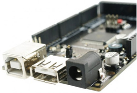
ADK Microcontroller Mega25 Cappuccino Board
Description:
ADK board came with a power jack, a USB connection, an ISCP header, and reset button. Also the board can connect up fifty four outputs/inputs pins. Those pins contained four UARTs with hardware serial ports, sixteen pins inputs, and fifteen pins PWM outputs.
The team decided to use this board instead of the Uno because it can regulate up to 18 servos without the servo shield controller. Moreover, it’s easier to code compared to the Uno where it required using servo shields controller (2-16 channels Adafruit servo controller board or 1-24 channels) and Uno board also needed to use library provided from the servo controller shield to code as well.
For each Power HD servo, it has 3 pins. One pin contains a control V+ and the other contains V-. V+ pin goes to the servo and the V- pin will be grounded. Digital Pin 30 to pin 47 of the ADK is use to connect the servos. Furthermore, algorithm test will be performed to test the maximum operation of the servos being used will only be 10 as the same time.
The efficiency of a voltage regulator, defined as is an important quantity of its performance, especially when comes battery life or heat. In order to protect the board, we will be using a voltage regulator to limit the current spikes.
We concluded that the Mega2560 can support up 50 digital I/O pins so it will be enough to run our Power HD servos.

ADK Board where the power supply connected to the voltage regulator and from the voltage regulator it connected to 18 servos.
Here is the video from the servos testing!


