RC Control Spring 2016

Posted by: Luis Valdivia(Project Manager)
Written by: Kevin Nguyen(Electronics and Controls)


Table of Contents:
– Introduction
– Transmitter and Receiver
– Setting up the MultiWii
– MultiWii GUI
– Arming and Disarming


Introduction:
Being able to use the RC controller early on in this project will be very beneficial since it will make testing safer and more efficient. Since EDF’s spin at very high rpms, it is not a good idea to keep your hands on the quadcopter while testing. The RC controller will allow you to test the quadcopter at a safe distance. An added benefit to using the RC controller is that it doesn’t add that much weight to your system. All that is needed for the quad to communicate with the controller is the receiver. This blog will guide you through setting up RC control.


Transmitter and Receiver:
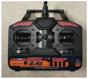
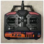
The RC controller that we used is the HK-T4A V2. This comes with a transmitter and a receiver. Most likely, you will be using the same controller as us so they would already be binded, but if not, follow this video to bind your devices. The transmitter will be from the remote controller. It will send a 2.4Ghz signal to the receiver on the MultiWii. The RC signal is much more reliable than bluetooth and is capable of transmitting at much further distances.
The transmitter controls the throttle, yaw, pitch, and roll of the quadcopter. The left joystick controls the throttle and the yaw; Vertical direction controls the throttle, horizontal direction controls the yaw. The right joystick controls the pitch and the roll; Vertical direction controls the pitch, horizontal direction controls the roll.

rc controller


Fig 1.1 RC Controller

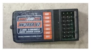
The receiver is connected to the MultiWii. Each channel on the receiver corresponds to a command on the controller. The transmitter sends out signals in the form of radio waves and the receiver converts those signals to electrical signals for the MultiWii to read. The connections on the receiver must be connected to the appropriate pins on the MultiWii in order to control it properly. Refer to this blogpost for MultiWii connections.

rc receiver

Fig 1.2 HK-T4A Receiver

Setting up the MultiWii:

To set up the MultiWii to be compatible with your quad, you need to download the MultiWii source code here. After getting the source code, go into the config.h file and select the appropriate configurations based on your project. To select an option, simply remove the comments(//).

For our project, we used:
#define QUADX
#define MINTHROTTLE 1150
#define MAXTHROTTLE 2000
#define I2C_SPEED 400000L
#define INTERNAL_I2C_PULLUPS
#define FREEIMUv035_BMP

Copy and paste this anywhere into the config.h file:
#define MAG_ORIENTATION(X, Y, Z) {magADC[ROLL] = -Y; magADC[PITCH] = X; magADC[YAW] = Z;}

Some things to mention are that the minthrottle should be kept as is. The quadcopter needs to be under a certain throttle to arm and if the minthrottle is set too high it won’t reach that arming point. Another thing is that for the board options, the MultiWii isn’t listed there, using FREEIMUv035_BMP would work as well.

MultiWii GUI:
The zip download for the source code included a GUI as well. The gui can be used to change the PID settings and calibrate the sensors. The GUI only monitors the sensors, you can’t control the device through it.

Arming and Disarming:
The most important commands for controlling the quadcopter is arming and disarming. Arming connects transmitter and receiver so that you can begin communication. Disarming disconnects the communication. If it flies out of control during testing, you can disarm to stop the motors from spinning. Typically, to arm you pull the throttle down and yaw to the right. To disarm you pull the throttle down and yaw to the left. This is convenient since you can arm and disarm with one joystick. The arming and disarming commands can be changed in the config.h file.

Works Cited:
https://www.youtube.com/watch?v=JyAyM1f_O3Q
https://www.arxterra.com/multiwii-esc-and-receiver-connections/
http://dl.btc.pl/kamami_wa/hk_27033_2.pdf



Spring 2016 AdBot Critical Design Review

The Rover should travel on level area, ramp area, and stair ways during the mission test.

Critical Design Review

By Dang Le, Project Manager

  • Dang Le (Project Manager)
  • Don Tran (System Engineer)
  • Muhammad Ali Siddiqui (Electronic Engineer)
  • Muhammad Maqbool (Manufacturing Engineer)

Executive Summary

Program Objective/Mission Profile

Program Objective

The project objective is to build a rover that will simulate a flyer distributor advertising CSULB’s Eta Kappa Nu social, guest speaker, and technical events on campus. Using a single power source the rover will launch from, and return to, an HKN advertisement booth and run in a general high foot-traffic area on campus which consists of flat areas, sloping areas, and stair ways, as shown in the course map. The rover will be controlled remotely using a computer with internet connection. Negotiations of budget resulted in the rover to cost less than or equal to $250. There is to be expected 0 to 16 mph wind during the course run on May 13th (Reported in Weather Report).
Mission Profile

The total distance is approximated in 344fts. The perimeter of the grass is 275 ft / 84 m. The north and south sides are leveled. The east side has 9 steps. The west end is a ramp.

Mission-CDR-72dpi

The front of USU building

The Design

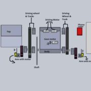
The main component in our rover design are including

  • Four drive motors (2 on the front and 2 on the back).
  • One gearbox motor (for the center).
  • Six wheels and tracks.
  • Two arms with supported by horizontal shaft and gear.
  • Pole holder for advertising and smart phone.

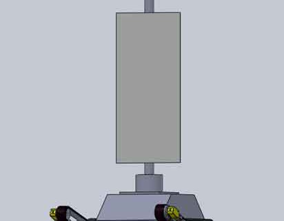
Adbotexplosive-72dpi

Project Features

  • Rover with advertising sign will be traveled up stairs and slope area in front of USU building.
  • Rover will be run and return to HKN advertisement booth in a single charge.
  • One shaft  with high torque gear box motor to support the lifting arms weight during the stair climbing.
  • Operator will be controlled remotely using Arxterra application with computer wifi connection.
  • Innovative wheels design to have a better track grip.
  • New aerodynamic body design to reduce weight and wind resistance

Custom PCB Design

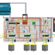
Fritzing diagram circuit with three H-bridge and I2C protocol IC to drive five motors with using Arduino and firmware coding.

CDR-Frizing-72dpi

Fritzing Diagram


Custom-PCB-72dpi

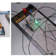
Breadboard testing transmit and received data with using H-bridge IC circuit and Arduino coding.


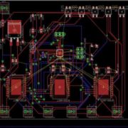
PCB layout

PCBlayout-CDR-72dpi


Hardware Design

By Muhammad Maqbool, Manufacturing Engineer

The body of our AdBot is set to be 12” x 8” x 2”. The Body is made of Aluminum. I got separate sheets of Aluminum each with a thickness of 0.125 inch and I welded them together with the help Ryland Walts. The reason for choosing Aluminum is that for our AdBot we wanted a strong body that would not get damaged if our AdBot hits the stairs or anyone try to kick it.

The body consist of two holes in the back each of a diameter of 0.16 inches, the holes provide a path for the driving motors to directly connect with the wheel. The two holes in the front of the body provides a path for the shaft to pass through and will be connected to the free moving wheels and arms.

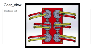
The wheels are printed using ABS plastic. ABS plastic is the most cost effective material. Each Wheel has a diameter of 2.5 inches and a thickness of 0.7 inch. The arms of the our AdBot will be of Aluminum as wheel, the arms will be 6” x 1” with a thickness of 0.125 inch. We have two motors in the front of the arm that will be driving the front wheels at all times. I have designed the gear for the shaft and the motor myself. As the motor rotates the gear on it rotates with it hence rotating the gear on the shaft and lifting the arms. I have designed two arm holder myself that will hold the arm on the shaft at all times.

The top of our AdBot is more aerodynamic by adding curves to it so it can go fast. The top is 12” x 8” and will sit on the body and I will screw them both. I will design a pole holder that will hold our pole hence holding our sign.

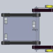
Adbot-topview-72dpi

top-CDR-72dpi Demension-CDR-72dpi

Software Design

Test code for controlling motors with Arxterra Application

SW-CDR-72dpi

SW-master-Slave-CDR


Project Update

By Dang Le, Project Manager

Work Breakdown Structure (WBS)

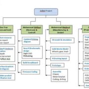
As a project manager, who created and assigned tasks for each member within the team throughout the project. A work breakdown structure (WBS) that showed each of team member who had responsible for their tasks. There could be a change during the mission task depend who has more free time and ability to take workload from other member. Here is our delegation tasks that showed in display below.

WBS-CDR-72dpi

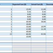
Budget Report updated

As a Project manager, I have to keep track on our budget to make sure it still within our given budget. The most expense is on prototype component and chassis. Unfortunately, our rover were bigger compare to previous semester, thus we have to look for the difference type of tracks that can support our rover during the mission test course. First, we thought we could use 6V DC motor for our rover ( these motor are free from previous semester), but now due to the rover is too heavy and may not be able to travel on stair ways and long distance, so we may replaced with 12V DC motor for final demo. Our budget report with expected cost right now without five of 12 V DC motors is $220.44.

Cost-report-CDR-72dpi


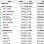
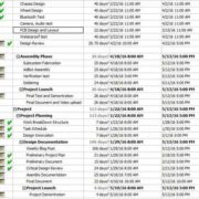
Schedule Updated

Project schedule is the software that used to create a task schedule and plan in this project for a specific date to be completed. As the project moved on, we could see which tasks we were completed or behind the schedule. The schedule showed in green check mark that indicated these tasks were completed. However, the main concern was the PCB schematic and PCB wiring layout. We have built a new schematic, which more complicated than our thought due to more parts on PCB and not enough clearance between one trace to another, thus our team member were having so much trouble when doing the layout. Furthermore, we were down by one of our team member electronic engineer. Thus, we were behind the schedule as our planned. Another issue was main tracks for our rover. The current track we have as the same last semester that was not support enough for our rover during the mission test. We are still looking for the tank track and 12 V DC motor with high torque for our AdBot.

ProjectSchedule1-CDR-72dpi ProjectSchedule2-CDR-72dpi


Status and Percent Complete

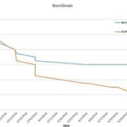
Here is the status and percent burn down  as we move along until this time. The charts showed that we were behind on software coding, PCB layout, and hardware as well.

PercentcompleteCDR-72dpi BurnDownCDR-72dpi

Project Demonstrations

click the link below to watch the AdBot demonstration

https://www.youtube.com/watch?v=CX5fDNFeUjc


Spring 2016 Additional Fan Bracket Design

Posted by: Luis Valdivia (Project Manager)
Written by: Juan Mendez (Manufacturing Engineer)

Table of Contents:
Introduction
Design
Conclusion

Introduction:
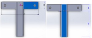
Since weight became an issue with our vehicle, we had to think of an alternative solution to fix the yaw problem. Our alternative solution was to add an additional brushless fan to counter the yaw problem. In order to add on another fan we needed to find a way to mount it on to the current frame. We thought of drilling new holes on to the frame to add on to the bracket, but instead of making new holes, we decided to use the ones that were already on the frame. In order to put the fan between two of the ducted fans, I had to use the holes that were between two of the current metal brackets. I modeled the bracket to be 1.67 by .31 inches as shown in Figure 1 so that they can fit perfectly between two ducted fans.

Figure 1 Demonstrating dimensions of 5th fanbracket

5thfanbracket

Design:

I wanted to make sure that the bracket would enclose the bracket provided by the brushless fan so I made the bracket extend approximately 1.25 inches as shown in Figure 1.
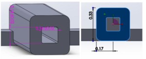
After measuring the bracket that came with with brushless fan, we saw that it was 3.4 by 3.4 mm thick. This is equivalent to .13 inches. In order to make sure that the brushless fan bracket could fit into mine, I made the inner cut of .14 by .14 inches so it can slip in smoothly as shown in Figure 2A. In order to make sure that the 3D printer could print the part without having it warp, I had to make the outer dimensions be .33 by .34 inches thick as shown in Figure 2B. This allowed the part to be printed without any trouble.

Figure 2A and Figure 2B Demonstrating dimensions of bracket design

bracket design

Conclusion:

The result were the parts fabricated shown below in Figure 3 A & B. The brackets were able to mount on smoothly into the brushless fans with no problem. They were then easily mounted on between the ducted fans on the vehicle as seen in Figure 4. Additional brackets were fabricated incase we needed to add a 6th fan to fix the yaw problem.

Figure 3A and Figure 3B alternate angles of 3D printed brackets

printed piece

Figure 4 5th fan attached to 3D printed bracket

attached

2016 Spring 2016: 3DoT David CDR ppt and CDR Debrief

BY: Omar Mouline (Project Manager),

On 04/20/2016 the the professor Gary Hill and with the assistance of the President gave us a debrief on our CDR. in the link blow is the CDR power point that was presented on the 04/06/2016 :

3DoT David CDR

Table of Contents

First slide:

Screen Shot 2016-04-25 at 8.58.19 PM

Remark:

Points were deducted For the picture used in the title page. The picture had to be a picture of our design.

Experimental Result

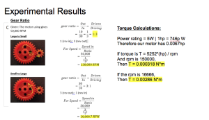
Screen Shot 2016-04-25 at 9.02.17 PM

Problem: 

The RPM calculation did not look right. The values were too large for the gear ratio we are using.

Solution:

The RPM calculation was recalculated and documented in this Blog Post:

  1. Gear Train

Subsystem Design: PCB Schematic

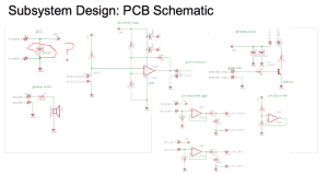
Screen Shot 2016-04-25 at 9.10.11 PM

Problem:

Capacitor value is too big for the PCB. what was the justification for the 2200 uF capacitor?

Solution:

The Electronics engineer worked with the division manager and they are planing to change the capacitor

President Remarks:

Create a training document on bypass capacitor.

Look at similar boards and copy them.

Hardware DesignScreen Shot 2016-04-25 at 9.17.20 PM

Problem:

Worried about the gearing and motor torque.

Solution

We were very precise on the correction of our studies on the subject and we have it all explain on these blog posts:

  1. Servos and Motor Trade-off Study Servos and Motor Trade-off Study
  2. Gear Train

Software design:

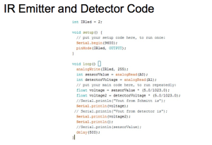
Screen Shot 2016-04-25 at 9.23.25 PM

Remark:

Detector code looked weak. This code was used just to test if the IR components functioned. The actual detector code will be developed and tested once the prototype is assembled.

Power report

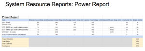
Screen Shot 2016-04-25 at 9.33.10 PM

Problem:

All values on the power report are under no load conditions. These values will change when the robot is operating.

Solution:

We will get the actual measurement of voltage and current for each component when it is operating.

Project Update

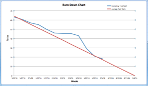
Screen Shot 2016-04-25 at 9.25.58 PM

Problem:

Lot of work were done over spring break, still more problems to solve.

Solution:

For the burndown the 50% for starting a task and 50% to complete the task does not give us an exact ready. The change of project design made us rush the tasks to come back on time. We finished a lot hard task in a very short time, we did our best and we were not on a little bit behind time, but since we were starting all the tasks and accomplished some it showed that we were in a good schedule.

General Remarks

  • Nice project schedule, does not look like on schedule.
    • it is normal since we changed the design.
  • have 3 caps for incoming power
  • Double check if the motors will work with system restrictions.

Spring 2016 3DOT Goliath, CDR Debrief

By: Ayman Aljohani (Project Manager)

Introduction:

Critical Design Review(CDR), is an important phase of the project, it presents the design of the project. It also provides a clear view on the project standing and percent completion.

After presenting our CDR, we were debriefed by the president, and the customer on our presentation content .

Here is  the debrief summary:


Title Page:

Was good, nothing to comment on.

Executive Summary

weakness:

Too much information was provided in  the executive summary

correction: 

Keep it short and simple

Only explain the major features of the project

System Design

weakness: 

Missing 3Dot Components on the System Block Diagram

Poly fuses

LDO

LIPO Charger

strength: 

Paul commented that the color coding on the system block diagram and  the legend, it was easy to follow. 

Experimental Results:

weakness:

Problem with the analog Schmitt trigger

However, Elec. Engineer, Kevin,  found out the problem and fixed the output of the threshold voltage on 4/20/2016.  The president is also notified about the fix on the threshold voltage issue.

Our goal of the Schmitt trigger is to convert analog signal to a digital signal.

Subsystem Design

No comment, it was good.

Interface Design

weakness:

messing 3DOT components.

correction:

Include 3Dot components

Custom PCB Design

weakness:

 The custom PCB  was not designed to be able to attach onto the 3Dot board as a shield.  The point of this design is to avoid the number of wires being used to connect to the microcontroller.

correction: 

Have custom PCB attach to the 4 pins on the 3Dot.

For future design reference it will follow a similar design shown by the following site:

https://www.adafruit.com/products/94

Software Design

weakness: 

The lockdown code that will disable the robot after 3 hits from the enemy was not included.

Verification & Validation Test Plans

Everything was good for the verification and validation test plans.

Project Updates

strength: 

Smartsheet is good to use  

weakness: 

 The actual cost of the free items was not included 

Fix the uncertainty for the resource report, it should be zero uncertainty. 

WBS should not have a repeated loop process

Project Demonstration

it was a good demo. 


UFO Torque Test Spring 2016

Posted by: Luis Valdivia (Project Manager

By: Anthony Becerril (Systems Engineer)

Table of contents:

  • Test objective
  • Test Procedure and Criteria
    • Preliminary work
    • Procedure
  • Results
  • Conclusion
    • Video
  • Appendix


Test Objective:

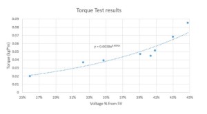
To create stable flight, the current quadcopter must not have yaw rotation being created by the Electric Ducted Fans (EDFs). This torque test will measure the necessary torque to counter the yaw rotation that exists. Theoretically, this torque will eliminate the yaw rotation and the counter torque will be produced via an additional fan to be implemented.


Test Procedure and Criteria:

Preliminary Work:

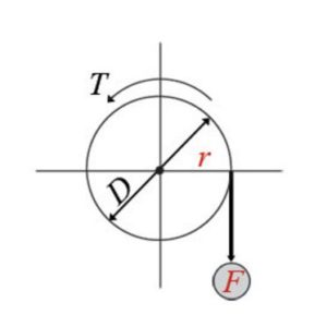
The torque seeked in this experiment will be calculated as follows:

Torque = F*r=F*(D/2)


r: radius; distance between center of rotation
D: diameter

F: force; force point

Figure 1.1 Representation of Torque setup:

Torque

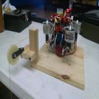
Figure 1.2 Set up used on UFO quadcopter:

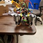
IMG_20160403_161323392

The setup built for this testing required the following:

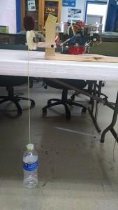
  • A pulley system to support weight like that of a full water bottle
  • A lazy-susan-like platform for quadcopter to spin on
  • An adjustable weight to vary on pulley during testing (i.e. water bottle)
  • A latching system to prevent the quadcopter from flying


Procedure:

The procedure to execute this test is as follows:

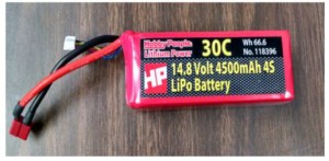
  1. Have fully charged battery ready [Appendix A]
  2. Upload corresponding Arduino IDE code to Arduino Uno
  3. Properly connect all necessary wires on quadcopter except for the battery [Appendix B]
  4. Place the quadcopter onto the set up turntable. Make sure the hooks are properly attached
  5. Have pulley weight properly attached to one of the EDFs
  6. Have potentiometer set to max before plugging in battery
  7. Plug in battery
  8. Tune potentiometer to turn on angle. Wait for calibration as indicated by the beeping code [Appendix C]
  9. Continue tuning potentiometer to higher thrust. Observe yaw rotation.
  10. If rotation exists, add more water to bottle. Continue this step until no rotation
  11. Take final weight and calculate final torque using the formula:

Torque=9.8ms2*radius *weight

Radius = 4.5” → 0.1143m

Weight= weight of object in Kg


Results:

Torques that were listed must have demonstrated rotation on the setup to be considered valid for our data collection.


Table 1.1 Data collected from eight tests:

Test # mass(kg) of bottle after throttle % from pot Voltage (V) to the ESC Torque (kgf*m)
in class demo 0.0609 43.12% 2.16 0.068216526
1 0.018 25.90% 1.30 0.02016252
2 0.035 34.70% 1.74 0.0392049
3 0.04 40.33% 2.02 0.0448056
4 0.033 32.26% 1.61 0.03696462
5 0.042 39.10% 1.96 0.04704588
6 0.046 40.86% 2.04 0.05152644
7 0.076 44.77% 2.24 0.08513064

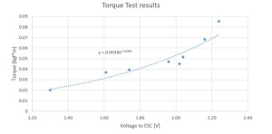
Figure 1.3 Plotted points torque v. voltage percentage from 5v to the ESC:

Percentage

Figure 1.4 Plotted points torque v. voltage provided to the Electronic Speed Controllers:

Voltage

Conclusion:

In conclusion we were able to gather multiple data points in our torque tests. Plotting our data points in excel, we can see the exponential trendline of the relation between torque of the quadcopter and voltage provided to the Electronic Speed Controller. These data points will help us understand how to maintain stability by producing our own counter torque. Using the 5th fan approach, we can determine what find to buy, based on necessary thrust to counter yaw torque. 

Click here for a video of the torque set up in action!

Appendix:

A. Battery Charging Manual

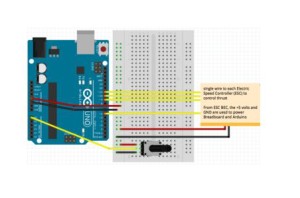
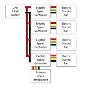
B. Wiring Diagram for Torque Test

Figure 1.5 fritzing diagram for torque test electronics:

FRITZING

Figure 1.6 cable tree of electronics:

WIRING DIAGRAM

C. Electric Speed Controller beep code

             Beep codes can be used for troubleshooting ESCs.

LiPo Battery safety Spring 2016

Posted By: Luis Valdivia (Project Manager)

Written by: Kevin Nguyen (Electronics and Control)


Table of contents:

  • Introduction
  • Using the IMax B6AC LiPro Balance charger
    • Charging
    • Discharging
  • Using the Voltage monitor system
  • Battery safety bag


Introduction:

LiPo batteries are the most dangerous types of batteries in the world. They are very compact in size yet contain very high power. This high energy density allows them to power devices for longer periods of time compared to other types of batteries but also makes them very explosive. LiPo batteries may explode and catch fire if overcharged, undercharged, charged too fast, undercharged too fast, or punctured. Although this seems scary, if handled properly, LiPo batteries can be just as safe as any other battery and will outperform most other batteries. This blog post will help you minimize the risk and reap the rewards of LiPo batteries.LipoBattery safety

iMax B6AC LiPro Balance Charger:

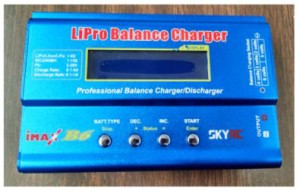
Most LiPo explosion incidents happen due to improper charging. This manual will help the user become familiar with the B6AC Lipo Charger to charge or discharge the lipo battery for the UFO quadcopter. Here are step-by-step guides on how to charge and discharge using the B6AC charger.

Lipo charger


  • Charging
      • Power charger from outlet with AC to DC adapter.
        • Once the charger is plugged into the wall, it should automatically turn on.  
      • Sift through the different modes using the DEC./◀ and INC./▶ buttons and through the options using the START/Enter button .
      • Select battery type using the BATT. TYPE/Stop button.
        • Be sure to select the correct battery type. There are different techniques for charging different batteries. Choosing the wrong battery type may burn down your house.
      • Select charging mode.
        • The preferable charging mode is Balanced Charging since it charges all cells evenly. To be able to use this mode you must have a balance connector on your battery. This is used to detect the voltage levels of each individual cell so that the charger can charge the appropriate cells depending on its level.
      • Select charging current.
        • More charging current will result in a faster charge. The general rule is to use the same value as the rated capacity(i.e. 4500mAH = use 4.5A charging current). It is acceptable to select a lower charging current, but do not choose a higher charging current unless specified in your batteries’ specs. Charging current may be limited by your AC to DC adapter. Since our wall adapter was only capable of producing 1A, we charged with a 1A charging current which might take some time.
      • Select battery cell count.
        • i..e. 4 cell battery = 4S
      • Plug the balance connector into the appropriate location on your charger depending on the amount of cells of your battery.
        • Pay attention to polarity.
      • Connect positive and negative ends of battery to charger.
        • An adapter is necessary to connect the two.
        • Connect the adapter to the charger before connecting the battery; this is to prevent shorting the battery. Shorting for long periods of time may cause fires.
        • When disconnecting, take the battery off first before the adapter; this is to prevent shorting the battery.
      • Once everything is plugged in and the correct options are selected, press and hold the START button for 3 seconds.
      • A screen should appear showing the amount of cells the battery is reading vs. the amount of cells the user set for charging.
        • If these two values match(R=S), press START/Enter to begin charging.
        • Once the battery is fully charged, the battery charger will beep to alert the user. Never charge past 4.2V per cell.
        • When storing the battery, it is best to charge no higher than 3.7V.   
      • While charging, the DEC./◀ and INC./▶ buttons can be used to view total voltage or individual cell voltages.
      • Press the BATT. TYPE/Stop button to stop charging.


  • Discharging
  • Select battery type.
    • Select discharge mode.
    • Select discharge current.
    • Press and hold Start for 3 seconds to begin discharging.

Note: Charging and Discharging too fast may damage the battery. Double check the charging/discharging rates to make sure it is compatible with your battery.                


Voltage Monitor Alarm System:

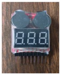
To prevent the battery from discharging to dangerous levels, a voltage monitor alarm system is used to alert the user of low voltage levels. Below is a quick setup guide for the low voltage alarm.

Lipo alarm

  • Connect the Balance Charging Connector to the Alarm.
    • The back of the alarm has labels showing the connections of each pin. Make sure the polarity is correct.
      • Once the Alarm has been successfully installed, an initial beep will sound to indicate that it is operating properly.
  • Press button at the top of the Alarm to select the lower limit of the voltage level.
    • This voltage level is used to compare against each cell of the battery. Once a cell goes below this value, the alarm will go off until removed.
    • LiPo battery cells should never go below 3V. It is recommended to set the lower limit to 3.2V to give some cushion time to remove the battery from the device.
  • After the device is connected to the battery, the 7-Segment display will display the value of the battery as well as the value of each individual cell.


Battery Safety Bag:

safety bag

When not in use, it is recommended to store the LiPo in a battery safety bag. In the case of an explosion, these bags are flame retardant and will prevent the fire from spreading. Only one battery should be stored in each bag. If more than one is stored in a bag, the effectiveness of the bag will be reduced and risk of burning down your house will increase. Stop using batteries that appear to be damaged. Overcharging or undercharging may cause gases to leak and make the battery appear puffy. The chemicals in the battery will ignite when exposed to air.

Works Cited:

  1. “The World’s Most Dangerous Battery.” The World’s Most Dangerous Battery. N.p., n.d. Web. 26 Mar. 2016. <http://www.atbatt.com/batterytimes/dangerous-battery>.
  2. “A Guide to Understanding LiPo Batteries – Roger’s Hobby Center – Radio Control (R/C or RC) Cars, Boats, Airplanes, Puzzles, Plastic Models, & Trains – Saginaw, MI.” A Guide to Understanding LiPo Batteries – Roger’s Hobby Center – Radio Control (R/C or RC) Cars, Boats, Airplanes, Puzzles, Plastic Models, & Trains – Saginaw, MI. N.p., n.d. Web. 26 Mar. 2016. <http://www.rogershobbycenter.com/lipoguide/>.
  3. N.p., n.d. Web. <https://www.pololu.com/file/download/iMAXB6ACmanual.pdf?file_id=0J525>.

Spring 2016 3 DOT Goliath body dimensions

By: Jerry Lui, Rickeisha Brown (Manufacturing Engineers):

Given the requirement of having the phone housed within the body of the rover the body must accommodate for the dimensions of the particular phone being used. In this case, a Samsung Galaxy S4 is being used as the camera for the rover and has the dimensions of 5.38”x2.75”x0.31” (1). Also, to be able to see through the horizontally placed camera a periscope will be used with a dimension of 13/16’’x13/16’’x1-1/16’’.

manufacturing 1


The top lid has a length of 5.5’’ which gives a clearance/play of 0.12’’. The top portion also has a slot to accommodate the periscope and is set to 1’’ (free space of 3/32’’ per side) to allow for movement and alignment of the scope.


Next, portions of the body was removed to reduce the weight of the rover with the sharp corners of the sections filleted with a conic rho profile. The conic rho profile (default solidworks value at 0.5) adds a smoother transition from the adjacent faces yet is able to keep close to the original shape of the cutout instead of having an extremely rounded corner.

manufacturing 2

Also, since we want to be able to access the phone quickly the top should be removable and to accomplish that without having seating issues both the top and the bottom has ledges that sit within each other. Tolerances will be given and set to 0.01574”or 0.4mm (2). The periscope gives a90°shift in the view so that we can see directly forward of the rover.

manufacturing 4


manufacturing 5

The side designs are simply easier to construct, since they are solely based on the top and bottom component configuration. The sides are also going to support the various housing of components such as: motors, batteries, 3dot board, and pcb.


As you can see by the figures above, the side components support the wheel axeling, from the motor to the wheel itself. The diameter of each hole measures 0.1” which is the diameter of our screws and our our rod components. This is the exact measure of the diameter of the rods and screws that are used for our rover.


The inner side features include ledges for the cellphone placement. The ledge is centered about the top measurement 5.50” and begins 0.53” from the top of the rover, consider the thickness of the cell phone, the periscope will sit just perfect outside of the body, with enough area to for viewfinder.


Sources

  1. http://www.gsmarena.com/samsung_i9505_galaxy_s4-5371.php
  2. http://makezine.com/2013/12/11/top-ten-tips-designing-models-for-3d-printing/