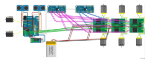
Chassis Fritzing Diagram
By Renpeng Zhang
Fritzing Diagram for Chassis.
Diagram
Description
Based on the interface definition, I created the fritzing diagram for the chassis part of the pathfinder. It consists of the Arduino Leonardo with two HC-SR04 ultrasonic sensors. It has the HC-05 bluetooth module connected to the Arduino through the TX and RX pins for the communication through a phone using the Arxterra app. Two servos is connected to the Arduino for the control of the pan and tilt of the rover. Two PCA9685 I2C expander were used for extra digital PWM and analog input pins. The VNH2SP30 motor driver is connected to the I2C expander and it’s used to control the speed of the motors. The built in current sensor of the motor driver is connected to the analog input of the Arduino for the monitoring of the current going through each motor. Battery was connected to power the motor drivers.

