Class Topics
Expand a topic for assignments and linked lectures.
#1: Welcome to TRC “The Robot Company”
Quote of the Day
“…I hit the interview with Northrop-Grumman out of the park. I had the one interviewer leaving the room saying he wanted his money back from his undergrad after hearing about the content I learned being in EE400D.”
Lab Task
1. The Robot Company Work Breakdown Schedule
- Over the semester it is important that you understand what your responsibilities are within the project. Just as important is an understanding of the roles and responsibilities of your fellow engineers. To gain this knowledge and to help you find your place in the class, please read The Robot Company Job Descriptions.
2. Write and Submit Cover Letter and Resume
Your first writing assignment is to generate and submit a Job Application to The Robot Company. This will be great practice for the cover letters and resume you will be writing for the upcoming job fairs. The hyperlinked document includes everything you will need to get started, including:
- Functional versus Written Cover Letter
- Tips from real companies, like Beckman Coulter on Resume Writing and Interview Skills
- What we at The Robot Company are looking for in your cover letter and resume.
- Sample Cover Letters and Resumes
- How to submit your cover letters and resume to The Robot Company.
- Your cover letter and resume should be in a single pdf document. The Name of the Document should be your name, Joe Smith.
- Submit your cover letter and resume in your EE400D Beachboard Dropbox, no later than Friday 6:00 p.m.
- Grading Rubric
#1.5: The Engineering Method
Quote(s) of the Day
“Each week (day, hour,..) is less important than the week (day, hour,…) before.”
Corollary
- Choose the difficult tasks to do first.
- Do not wait for instructions. Apply your critical thinking skills to work independently.
Old Business
New Business
Assignment Due Dates
Lab Task
Research
Research Presentation Template
“Engineers should always try to build on what has already been done before. Information on related problems that have been solved or unsolved may help engineers find the best solution.”
- Working from your job description, research similar work reported on the web and for legacy robots review Blogs from earlier generation robots. In the latter case consider the quality of the post.
|
- It is hard to overstate the value of this initial research. If you are in doubt, as a cautionary tale, I recommend reading the following Case Studies.
Research Case Studies
- Case Study – Pick and Place
- After a suggestion was made that a Makeblock XY – Plotter could be an excellent platform on which to build a pick and place machine, the team immediately purchased the plotter and modifying it to be a pick and place machine. In the end the project achieved all its goals.
- Lesson: While it is hard to argue with success, and in this case showing the initiative to move forward as quickly as possible, two problems present themselves. The purchase of this $300 dollar plotter was not approved by the department and therefore the students may have had to fund the project. If the plotter did not meet design requirements, and in multiple instances it did not, the students again would have had to fund the project. Instead of focusing on the strawman solution the students may have wanted to do their homework, and may have found in less than an hour, the PP4 – SMD-Pick and Place Machine and Paste Dispenser. This DIY project includes a pdf file listing all the components needed to make the project.
- Case Study – Project BiPed Robot
- For 12 weeks the software engineer was stopped by a single broken link on the Project BiPed website. After the Critical Design Review (CDR) and a few minutes of detective work the Project BiPed RoFi software download page was found.
- The software plus documentation was also found on the previous semester’s last blog entry – the first one the software engineer should have read.
- Lesson: First, do your homework and then if you still need help getting past a problem talk to your management team.
- Case Study – Velociraptor
- The core software engine used by walking robots like Biped and Velociraptor are the same. For 15 weeks these two teams never spoke to each other.
- Lesson: This exactly why we have Division meetings.
- Case Study – SpiderBot
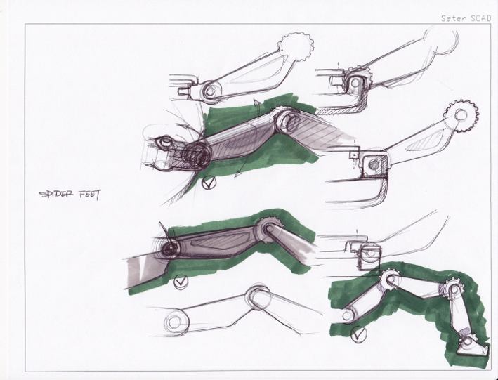
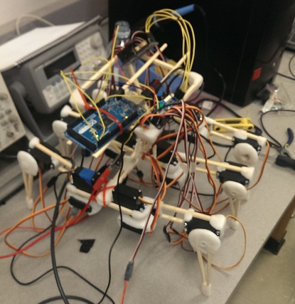
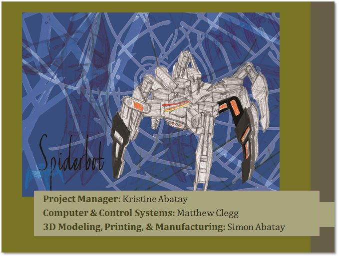
- After being given a HEXBUG robot, the spider robot team took the HEXBUG apart, rendered all the parts in Solidworks and then after 12 weeks of hard work, realized it could not be duplicated using available 3D printers. After a few minutes on the internet, three 3D printable spiders designed by Jerry Mantzel, Joe Klann, and Theo Jansen were located. Ultimately, an original design was implemented in only a few weeks.
- Lesson: First, do not focus on the first “strawman” solution presented to you. Follow the engineering method beginning with doing your homework. Second, the whole team needs to sign-off on the final design concept. In this example, the mechanical engineer should have understood the limitation of the fabrication tools available to his/her project and brought these limitations to the attention of the team.
- Case Study – Rover
- The sum total of the design at CDR was two 3D printed sheets of plastic – one included two bends. Further, the prints were not coordinated with the Division manager or was funding approved by the department.
- Lesson: The mechanical engineer did not do their homework, which after only 15 minutes research would have found reference models. Next, the wrong machine (3D printer) was used. In addition, the engineer should have requested help from the Division manager in locating the correct machine (laser cutter). Finally, without approval, the student may have had to pay for these 3D prints.
#2: Stakeholder Expectations
Lab Task
- The Task Matrix
- Creativity Exercise
- Creativity Presentation Example
- Remember…
- The presentation should illustrate the evolution of a “crazy” idea (Hover Board” to a practical solution (magnetic levitation).
- All creativity methods (Dunker diagram, attribute listing, and lateral thinking) should be integrated into Brainstorming Approach (not assigned to individuals)
- Tour of the Cabinets
Creativity Exercise
- Applying what you learned in the Creativity lecture to help the customer define the mission. Develop your creative solutions using the following methods.
- Dunker Diagram
- Brainstorming Approach
- Attribute (Properties) Listing
- Lateral Thinking
- Forced Relationship Technique
- Different Point of View
- Assign one team member to be the moderator for one of the creativity tools. The entire team must participate with different team members trading off as the moderator.
- The creative process is iterative, with one idea (often impractical) leading to another. For example; Create an innovative alternative to IR lights used to reflow solder surface mount devices (SMDs) onto a printed circuit board (PCB). This traditional approach does not provide uniform heating of the board, resulting in burnt boards on one side to cold solder connections on the other side of the board. Camp Fire – used to fire clay over 16 thousand years ago, lead to kilns lined with fire bricks, use fire bricks with electric heating elements to generate a uniform IR source for reflow soldering.
- Identify representative solutions developed by the group which are out-there and innovative. Avoid existing “known” solutions for solving the problem. If applicable, highlight (star) two (2) and not more than four (4) promising design solutions for each problem.
- Do not be concerned that you will be required to implement these solutions. Consider these alternatives ideas to be weighed against more traditional non-innovative solutions (see next bullet point).
- Make a list of questions/experiments that might help you determine the best solution for each problem. This list should contain both innovative and traditional non-innovative solutions.
- Document your work in a PowerPoint presentation to be given next week. The moderator should talk about the creativity tool for which he/she was the moderator. Grades will be assigned on an individual basis.
Presentation Outline
Prepare 1 slide per subject, with the total not to exceed 8 slides and take no more than 8 minutes to present.
For grading purposes, please follow this outline exactly, do not deviate.
- Candidate and Selected Problem(s)
- Dunker Diagram
- Brainstorming Approach
- Attribute (Properties) Listing
- Lateral Thinking – Forced Relationship Technique
- Lateral Thinking – Different Point of View
- Promising innovative alongside traditional solution(s).
- Questions/experiments that might help you determine the best solution(s).
Case Studies
- Prosthetic Arm
The Prosthetic Arm used the Dunker method to discover the VA hospital solution (do not have an amputee, do have an amputee)
- Pathfinder Solar Panels
Make solar panels lighter (based on incorrect problem statement), make solar panels heavier – move cg lower so it does not tip over. In this case study, the Dunker method helped the team discover the real problem.
#3: High Level Requirements
Old Business
New Business
Assignment Due Dates
Lab Task
- Customer Objectives
- Draft of Level 1 Requirements
- Divison Resources
- Robot Kit (Shared Google Document)
- Review of the reference blog posts
Requirement Evaluation Rubic
- Is the requirement, Quantitative, Verifiable, and Realizable?
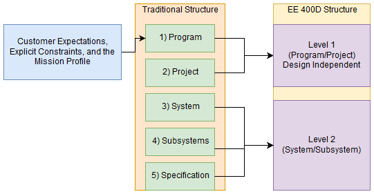
- Is the requirement located at the correct level (1 – Program/Project, 2 – System/Subsystem)
- Is the requirement response to a higher level requirement or customer’s objective (Requirement Flow Down)? Is the linkage clearly defined?
- Does requirement provide links to the source material?
- Does the requirement move the design process forward?
- Are equations used to calculate a requirement provided and are answers correct?
- Is language in the form of a requirement?
- Avoid multiple requirements within a paragraph. (i.e., breakup statements that contain multiple requirements)
- The requirements that are missing are the hardest to discover and will be factored into your evaluation. Use your strawman design to help you find them.
#4: Derived Requirements and Modeling
Old Business
New Business
Assignment Due Dates
Lab Task
- Division Training
- Projects should continue to work on Task Matrix and Level 2 Requirements.
Design Process and Modeling
- Draw a preliminary sketch of the design
- Make a back of the envelope calculation
- Conduct a trade-off study
- Model the System
- Mathematical Model
- Computer Simulation
- Full-scale Prototypes
- Scale Model
#5: Realistic Constraints and Standards
Old Business
New Business
#6: Preliminary Design Review
Old Business
New Business
Assignment Due Dates
Lab Task
Project Meetings
- Assign due dates to all tasks and allocate points across the task matrix.
- Review of Research Projects/First Blog Post (see Preliminary Project Document outline)
- Work on assigned tasks (task matrix)
- Project managers should translate task matrix into a schedule.
- Generic Schedule
- Microsoft Project and Project Libre Burn Down
Division Meetings
MST
- Did you…
- Training Plan plus quiz schedule – 3DoT documentation quiz next week?
- Find common and unify Requirements/tasks across the projects
- Status of Collaboration between MST and E&C
- NASA System Engineering Handbook Appendix C: How to Write Good Requirement
- 3DoT – Training Documentation
- Simple Robot Project Folder
- Identification of custom PCB(s)
E&C
- Review of E&C Technical Training Plan (does it include the following)
Manufacturing
- Solidworks Strawman Models
Quality Assurance
- Make sure Blog is posted to the correct location on the website. Do not post to more than one area. If we cannot find it we cannot grade it.
- Clearly identify project member(s) who and how they contributed to the post. If this information is not included then no grade can be assigned.
- Do not plagiarize material. For example if you use a photo, as a minimum provide source. See University “Cheating and Plagiarism” policy for more on this topic.
- Failure to follow any of the following directions will result in an automatic grade reduction.
- Once posted only your “Introductory” paragraph should appear on the project page with a “Read more à” link.
- Blog post must include a square teaser photo.
- All blog post must include image(s) for illustrative purposes. See presentation and starter kit to learn how to format images for upload. Failure to “optimize” images result in long periods of time from upload to the photo appearing within your blog post. This often leads to multiple uploads, with the instructor spending time deleting photos in the media folder.
- Please use courier font and single spacing on Code examples.
#7: Career
Old Business
New Business
Assignment Due Dates
Lab Task
Project Meetings
- Review Project Budgets or How to lower cost
- PDR Debrief
Division Meetings
MST
E&C
Manufacturing
- Solidworks Cable Routing
- Madell Pick and Place
- MUSE Laser Cutter
#8: Preliminary Design Review (PDR)Preliminary
Announcements
Assignment Due Dates
Lab Tasks
PDR
- PDR Checklist
- Schedule
- 2 PM – ModWheels Starts
- 2:40 PM – ModWheels End
- 2:45 PM – 3DoT Chassis (Pete-Bot) Starts
- 3:25 PM – 3DoT Chassis End
- 3:30 PM – BiPed Starts
- 4:10 PM – BiPed End
- 4:15 PM – Goliath Starts
- 4:55 PM – Goliath End
- 5:00 PM – Sojourner Starts
- 5:40 PM – Sojourner Ends & Break Time Starts
- 5:50 PM – Break time Ends & ModWheels Demonstration Starts
- 6:00 PM – 3DoT Chassis Demonstration
- 6:10 PM – BiPed Demonstration
- 6:20 PM – Goliath Demonstration
- 6:30 PM – Sojourner Demonstration
- 6:40 PM – End
#9: Critical Design Review (CDR)
News and Announcements
Old Business
New Business
Assignment Due Dates
PDR Generic Comments
- Use material from previous semesters with extreme caution. Recommended that you do your own work and then check against previous work. Too much “incorrect” material taken from previous semesters.
- Division Management
- Division managers need to help and review work product of division members.
- Division Managers are reasonable for material covered by Division Members
- Division Manager grade may be based on Division Members grades on member’s work products (major reviews and blog posts).
- More Research…
- Use Rocker-Boogie as a model of how it is done.
- Requirements, Verification, and Validation
- L1 and L2 should be a more quantitative allowing easy verification testing. Verification is not during the mission which is validation.
- Qualitative using adjectives and TBDs
- Any visual inspection is a “will”
- Nothing is verified during the final. The mission is for validation Only.
- 3DoT Project Notes
- 3DoT robots are required to use the onboard battery only.
- 3DoT robot dimensions should match those of the 3DoT board
- 6 hour (2/2/2) Print Requirement
- Resource Management
- Mass and Power Project Allocation
- Other Resource example would be 3D Print Time
- Tasks
- Word “Trade-off study” used where MODEL should be
- Back of the Envelope does not equal Pencil Drawing with Dimensions.
- Avoid generic task descriptions on the project schedule. The schedule is a guide to the entire team.
- Project and Systems Design
- PBS (Product Breakdown Structure)
- Label axis on burndown with vertical line showing today
- If you are planning to use a 3D Printer versus a Laser Cutter, do not use outline and extrude with Solidworks add a third dimension (nut capture, ribs, …)
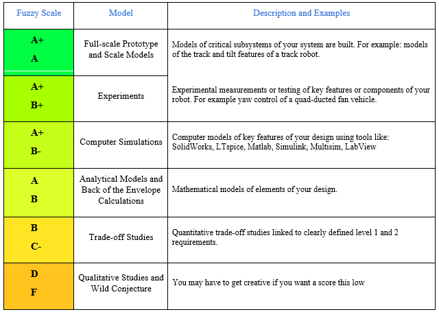
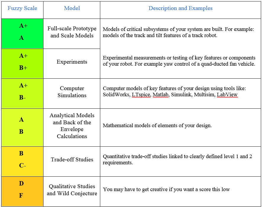
Model Grading Scale
- Here is a first draft of the grading scale we will use to evaluate the models you produce. Keep in mind that this is a fuzzy scale, and should not be taken as canon. Combining multiple modeling steps to address a particular design problem (for example a back of the envelope calculation –to- a computer simulation -to- an experiment –to- a full-scale prototype) increases the chance of getting many high grades.
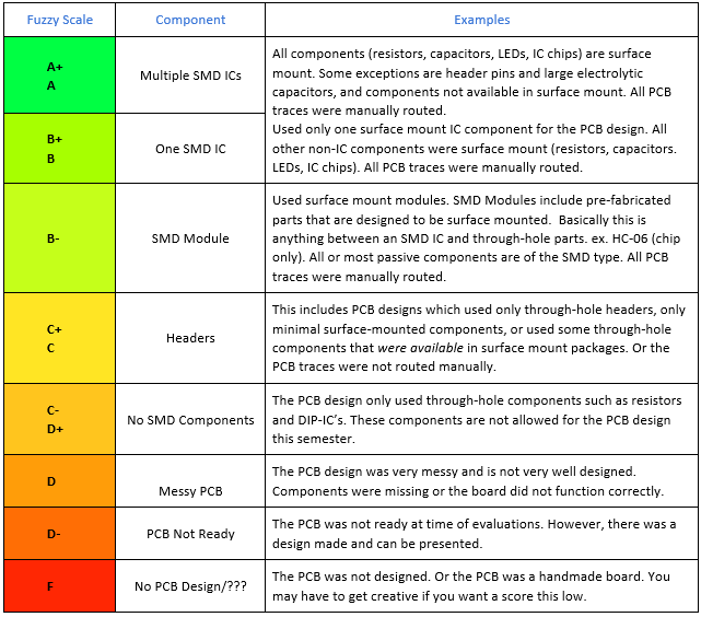
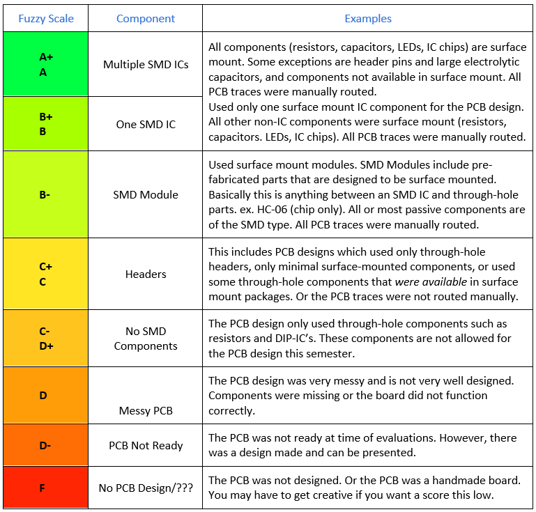
PCB Grading Scale
- Here is first draft of a grading scale we will use to evaluate the custom PCB you produce. Keep in mind that this is a fuzzy scale, and should not be taken as canon. Here are a few examples of what SMD ICs look like and here is a nice introduction to IC Packages from our good friends at SparkFun. Well-designed boards with using only surface mount components will achieve higher grades as outlined in the rubric below. Obviously, the PCBs and components you use need to be functional. No credit is given for chips laid down that serve no function or do not work.
#10: Critical Design Review (CDR)
News and Announcements
Old Business
New Business
Assignment Due Dates
CDR Debrief
- Do not blindly believe what the computer (or the internet) tells you. Use common sense.
- Requirement flow down ultimately is realized in the components selected.
- Please show how the engineering method resulted in the selection of key electronic and mechanical components.
- This may result in the generation of higher level requirements. If this occurs highlight these new requirements.
- For example, Pathfinders desert environment requirement needed to be factored into the selection and design of the rotary encoder.
- If your project has a user interface, (i.e. Arxterra Control App, etc.) make sure your images are screen captures of your original custom interface. Specifically, they should show the custom commands you have implemented.
- All allocation reports’ format should not change from PDR (Expected, Actual, Uncertainty, Margin, Source)
- Do not change “Expected” value to “Actual” value.
- Leave Expected at PDR values.
- Cost reports “Expected” should not change from PDR.
- Do not show only money spent to date.
- Table should clearly identify money spent to date and money to be spent.
- Other resources
- Do not forget to give allocation resource report for 3D printing time if applicable
- 3DoT projects must follow 2,2,2 = 6 hr. print time
- Multiple power reports are often required when using a 3DoT board
- 5v Boost current (mA)
- 3.7v Battery current (mA)
- 3.7 Battery capacity (Ahr)
- Charging time (hr)
- For battery capacity do not forget depth of discharge.
- Finally, get your units right!
- Do not forget to give allocation resource report for 3D printing time if applicable
- The best source of information is the datasheet, not a previous semester. For example, current capability of your battery.
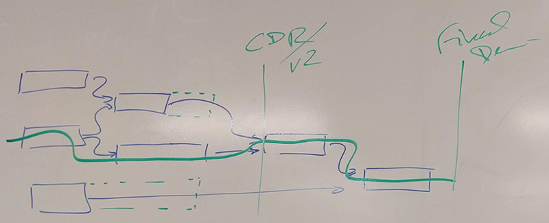
- Listing tasks (and only those tasks) along the Critical Path is required on the second slide in the schedule section.
- Be on time to class (Your project team are counting on you).
- Presentation are due an hour before class. Place in BeachBoard drop box.
- Consult with your Management team (President, Project, and Division) on when they require your material so they can review.
- Keep you division management in the loop! Remember, their grades are also based on the material you present.
- This review material should allow time for the material to be revised if needed.
- Software detailed definition, for the most part, should be completed by CDR. Software coding should not be far behind.
- Clearly identify test versus actual mission ready code.
- Overly simplistic PCB designs.
- Duplication of tests reflects poorly on Division communication and coordination. For example; servo testing with hanging weight.
- Design Process
- Draw a preliminary sketch of the design
- Make a back of the envelope calculation
- Conduct a trade-off study
- Week 4: Design Process and Modeling – Models facilitate the design process. A model simplifies a system or process so that it may be better studied, understood, and used in a design. There are three common models used in engineering:
- Mathematical
- Computer Simulation
- Physical Models
- Full-scale Prototypes
- Scale Models
- Solidworks designs are not models unless applied to a simulation. For example load testing.
- Plagiarism from previous semesters leads to disaster.
- You do not understand material presented.
- Cable tree does not address plan for routing cables.
- Material is obsolete
- Resource reports, including power allocation
- 3DoT command software
#11: CDR Presentations and Project Demonstrations
News and Announcements
Assignment Due Dates
Lab Tasks
CDR Project Presentations and Demonstrations
- Schedule
- 2 PM – ModWheels Starts
- 2:40 PM – ModWheels End
- 2:45 PM – 3DoT Chassis (Pete-Bot) Starts
- 3:25 PM – 3DoT Chassis End
- 3:30 PM – BiPed Starts
- 4:10 PM – BiPed End
- 4:15 PM – Goliath Starts
- 4:55 PM – Goliath End
- 5:00 PM – Sojourner Starts
- 5:40 PM – Sojourner Ends & Break Time Starts
- 5:50 PM – Break time Ends & ModWheels Demonstration Starts
- 6:00 PM – 3DoT Chassis Demonstration
- 6:10 PM – BiPed Demonstration
- 6:20 PM – Goliath Demonstration
- 6:30 PM – Sojourner Demonstration
- 6:40 PM – End
#12: Final Documentation
Old Business
New Business
Assignment Due Dates
Lab Tasks
CDR Review
- CDR Debrief with each project
#13: Project Implementation
Old Business
New Business
Assignment Due Dates
Lab Tasks
- Start V&V Reviews
- Grade Status
#14: Housekeeping
News and Announcements
Old Business
New Business
Assignments and Due Dates
Lab Tasks
- Review of Verification and Validation Plans and Reports
- I recommend returning parts on loan, except those integrated into the project, today – avoid the crunch.
- Get projects mission ready.
Mission Accomplished
- Verification and Validation Reports
- Updated and Printed Verification and Validation Checklists and associated Test Reports are Due at the time of the Demonstration
- Updated Checklist broken out by Division and Type (Will, Shall, Should). Unless otherwise directed (approved), verification will be at the system level.
- Request waivers on tests you are not planning on conducting. It never hurts to ask.
- Provide link to PDR System Level Requirements Do not include unlinked requirements. In other words, a system level requirement which is not linked to a project requirement. Again, unless approved, subsystem verification is not factored into your grade.
- Include a “Change Control Page” at the beginning of the Test Report. See SMD Pick and Place for excellent example.
- Checklist may include percent complete versus a simple Yes or No.
- Common mistakes: quantitative (no sharp edges), missing requirements (flight time, safety).
- Grading Note(s)
- Points deducted for use of glue gun and other adhesives like epoxy, twisted non-soldered wires, poor workmanship, tape, zip ties, etc.
- Non-mission Critical Parts
During the final week of class (not during final’s week) teams will return parts on loan or purchased with University funds and not required in support of the demonstration. Please bring paper versions of all relevant emails and receipts to expedite the process.
Promotional Video on the Engineering Method
- The objective of the video is to provide a fun and positive overview of the engineering method and project. The video may be used for promoting the electrical engineering department to the college and outside world (e.g. as a recruiting tool).
- Reference Video: You can view previous videos here.
- Time: Approximately 2 minutes
- Music: Non-copyrighted instrumental track. Here is a good source of non-copyrighted material http://www.mobygratis.com/catalog
- Voice Over: Optional but recommended
- Video: Please do not use copyrighted material (e.g. clips from movies)
- End Credits: Second to last clip should thank our sponsors (for example: 4PCB and Arxterra) including by name and corporate logo. The final clip must always show CSULB Emblem and give credit to the COE/EE department.
- Do not enable commercials on your YouTube videos. Here is a tutorial on how to “Turn Off Ads on YouTube Videos.”
- Grading
- Points will be deducted if the video is not turned in on time and the above instructions are not followed.
- Do not forget to illustrate the Engineering Method through your Project Video with voice-over and/or text overlays.
- Please provide in your accompanying email, who participated in the creation of the video and to what extent.
Blog Posts - Common Errors
- Blog Posts should have a descriptive title, show a square teaser photo plus a short introductory paragraph with Read More à tag.
- Post should indicate semester
- Title should describe content
- Teaser photo must be square
- Verify short summary paragraph is on project home page. (prosthetic arm/hand)
- If missing “Read More” tag you probably have the complete blog post on the project page.
- Code must include helpful comments and should be single spaced done in Courier font
- Too much space between paragraphs
- Image Size and Number
- Images should be under 200 Kbytes. See “How to Blog Post – 101”. And only upload once (Arxterra/public_html/www.arxterra.com/wp-content/uploads/2017/01 – 04). All of these files are over 400K. Interesting that the biggest files are also uploaded multiple times – which should tell you something!
#15: Final Information Filing
Assignments and Due Dates
Additional Information
Do Not Forget
Verification Report
- Updated and Printed Verification and Validation Checklists and associated Test Reports are Due at the time of the Demonstration. Verification will be at the L1 level (minimum) and L2 on a time available basis. Request waivers on tests you are not planning on conducting. It never hurts to ask.
- Provide link to PDR System Level Requirements Do not include unlinked requirements. In other words, a system level requirement which is not linked to a project requirement. Again, unless approved, subsystem verification is not factored into your grade.
- Include a “Change Control Page” at the beginning of the Test Report. See SMD Pick and Place for excellent example.
- Common mistakes: quantitative (no sharp edges), missing requirements (flight time, safety).
- Checklist may include percent complete versus a simple Yes or No.
- Grading Note(s)
- Points deducted for use of glue gun and other adhesives like epoxy, twisted non-soldered wires, poor workmanship, tape, zip ties, etc.
- Non-mission Critical Parts
During the final week of class (not during final’s week) teams will return parts on loan or purchased with University funds and not required in support of the demonstration. Please bring paper versions of all relevant emails and receipts to expedite the process.
Class Lectures
Organized list view of all lectures.
The EE400D Robot Company
Table of Contents
Three Project Management Structures
- Functional Organization
- Project Teams
- Matrix
Functional Organization
- Engineers working on the project work within the company’s existing functional organization.
- Coordination is maintained through existing company management structure.
- EE400D, a classroom of future electrical engineers, is not a real company and has no existing company management structure. Our functional organization will therefore reflect the common functional elements of our projects. This was a key consideration in the selection of our candidate set of projects.
Project Teams
- The company (instructor) assigns engineers to a project team which remains intact over the life of the project (the semester)
- This structure is simple, cohesive, and most important the one which you are most familiar.
- Unfortunately this structure has many disadvantages.
- No training. You are assumed to be technically proficient in your area of responsibility on day 1.
- No sharing of technology expertise or resources.
- Difficult post-project transition. A real problem in a company with thousands of engineers.
- For these reasons, the Matrix organization is the typical structure you will find in large organizations like NASA’s Jet Propulsion Laboratory.
Matrix Organization
- Our class is organized as a matrix type organization as defined in the following two articles. Note that the x and y axis of our matrix is reversed from the generic matrix organization cited in these articles.
|
In my experience, projects just seem to work best with a balanced matrix type of organization. This is because the resources of the company are permanent (or relatively permanent) and projects are not. A project is a temporary undertaking with a known ending. Project teams are formed for the life of a project. This means that we are able to bring the right resources together for a project and use them for the amount of time they are needed. Organizing the Organization for Project Management |
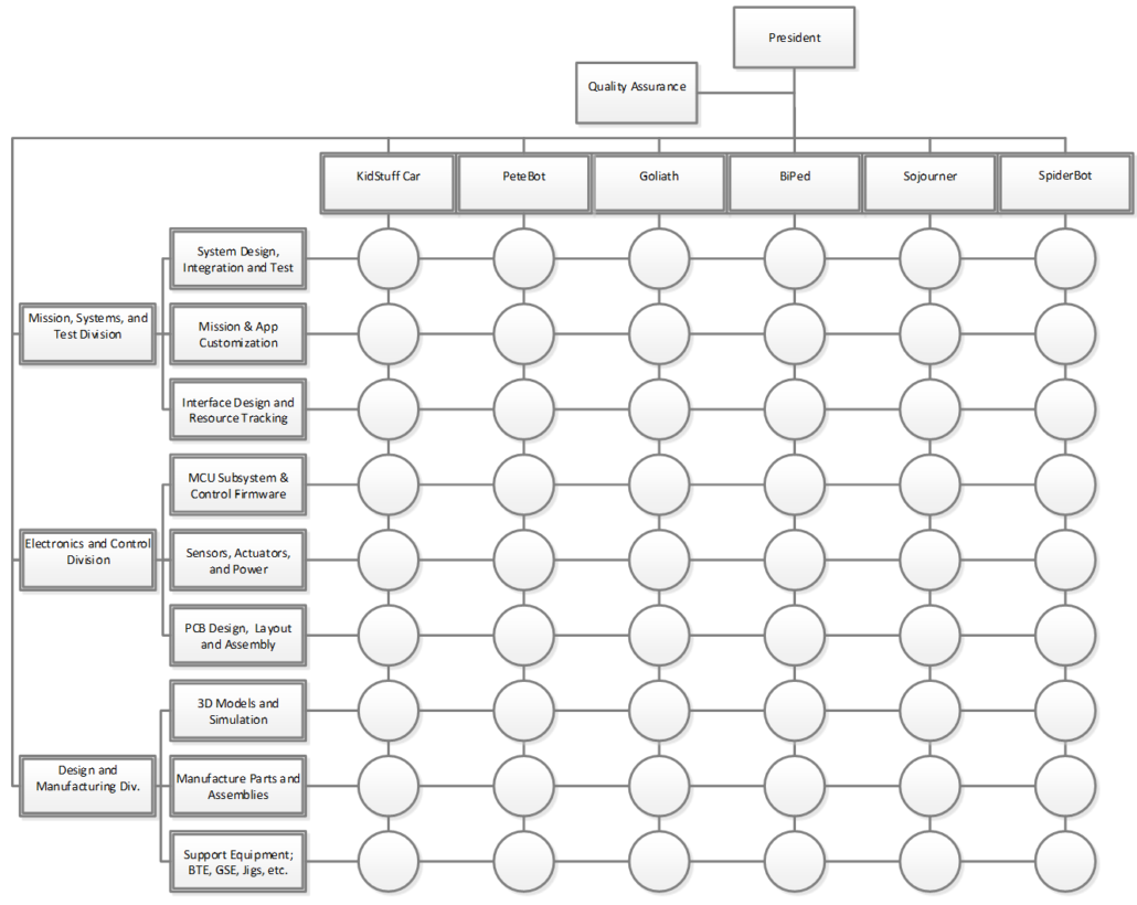
- The Matrix is a Hybrid organization where projects are overlaid on the company functional structure. For our class our functional organization is based on the common components of our robots.
- Notice that our functional organization forms the vertical axis of the matrix.
- In a matrix organization you report to both a project and a line manager.
Robot Company Matrix Organization
Line Management
- From the perspective of the company matrix, the Functional Organization is the vertical axis and describes the division’s sections, and groups that make up the company.
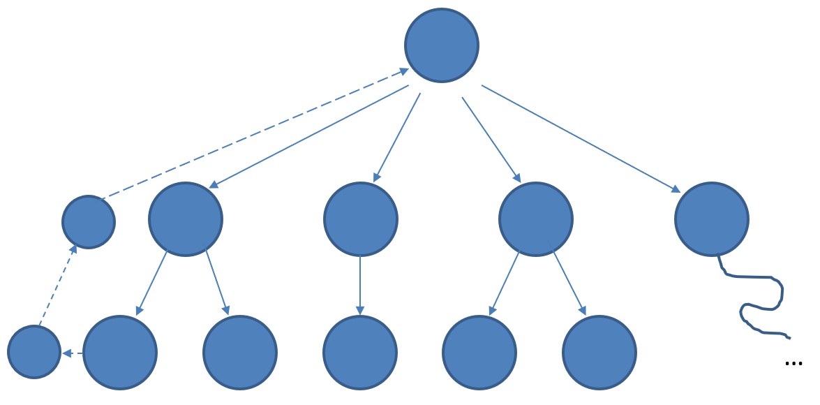
- Using NASA’s Jet Propulsion Laboratory as an example each node (circle) is a group of engineers who report to a group supervisor. These group supervisors in turn report to a section manager, who are at the end of each horizontal line in the matrix. Also seen in the matrix, each section manager reports to a division manager who in turn reports to the president. This is the Line Management of the company.
Table of Contents
Suggested Reading
NASA System Engineering Handbook Section 6.1.2.1 “Work Breakdown Structure” and Section 4.3.2.1
“Product Breakdown Structure.” Also, review page 312 Figure G-1 where a PBS Example is provided.
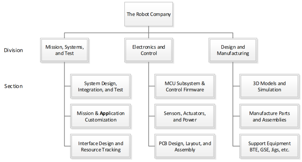
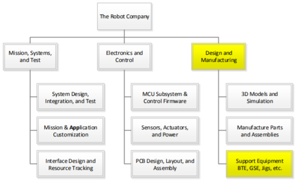
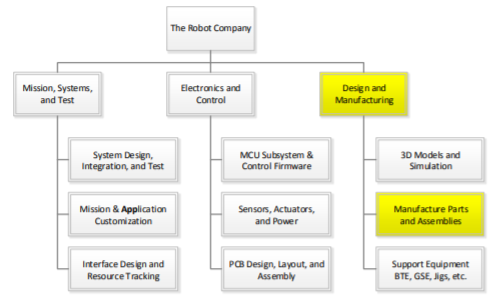
The Robot Company WBS
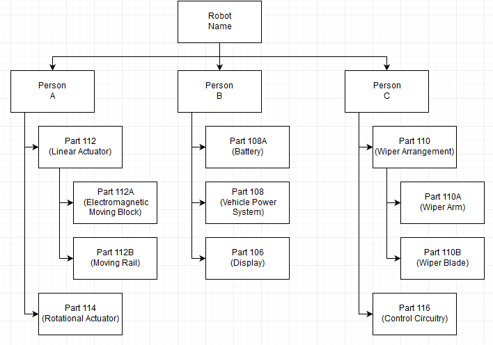
This document describes how The Robot Company is structured technically known as the Company Work Breakdown Structure (WBS). From your perspective, the WBS describes your responsibilities within the company. In that spirit, I have worded the sections in the form of Job Descriptions and named the document accordingly.
|
As the names imply the WBS provides a breakdown of the work that needs to be accomplished to build the product, while the PBS provides a breakdown of the product ITSELF. |
During the first phase of the project, your manager will create a project WBS, based on this one but adapted to your specific robot. Later in the semester, you will hear the term Product Breakdown Structure (PBS). The PBS describes the parts (functional blocks) of the robot. The PBS is the responsibility of the System Engineer.
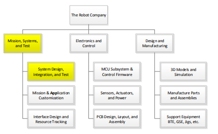
To make sense out of the following material, please refer to the Company Matrix Organization Chart presented earlier and the Figure 1 Company Work Breakdown Structure. To learn more, read Section 6.1.2.1 “Work Breakdown Structure” and Section 4.3.2.1 “Product Breakdown Structure” in the NASA System Engineering Handbook. On page 312 Figure G-1 a PBS Example is provided.
Figure 1 Company Work Breakdown Structure
If the parts of an organization (e.g., teams, departments, or subdivisions) do not closely reflect the essential parts of the product, or if the relationship between organizations do not reflect the relationships between product parts, then the project will be in trouble … Therefore: Make sure the organization is compatible with the product architecture – Conway’s law
The Customer
Task Summary:
- Define mission objectives
- Set cost and schedule goals based on inputs for the project manager and Electrical Engineering Department chair.
- Validate project design
The Robot Company President
The president is responsible for the management of all Robot Company projects. Coordinate working from the customer’s mission objectives to develop the program requirements for each project. Will allocate limited financial resource between projects.
Task Summary- Work with the customer(s) to define Program/Project Level 1 Requirements
- Train Project and Division managers
- Ensure company meets cost and schedule goals set by the customer(s)
- Support project and division managers
- Look for synergy between projects
- Assess performance of Project and Division Managers
As the president, you will be responsible for the management of all Robot Company projects.
Working from the customer’s mission objectives, you will develop the program requirements for each project.
You will also work with the customer to allocate limited financial resources between the projects. You will be scheduling all project deliverables including the Project Plan, Preliminary and Critical Reviews and Associated Documents.
You will be working closely with our project managers helping them manage cost, schedule, and performance, including…
- Assisting the project managers in their preparation for reviews and written documents.
- Assisting the division managers in the development and execution of their training plans.
Working with the project and division managers, you will also identify areas of synergy between the projects allowing better utilization of limited engineering resources.
Keep close communication with joint projects (cross course integrated projects) to ensure each division manager, project manager and engineer are in agreement and compliance with the Interface Control Document (generated by Mission, Systems and Test Division). Requires close communication and collaboration with the presidential counterpart in second-course section.
Along with the customer and management staff, you will, on a periodic basis, assess each project and division manager’s performance.
Qualifications
An educational background in business and/or management experience, or a desire to learn is a plus.
Quality Control Engineer
The QA Engineer working with the project and division managers, will insure that project plans, documentation, presentations, and blog posts are consistent with those generated by working engineers and reflects well on the CSULB COE and EE department.
Task SummaryInsure quality is built into each project. For example, is the robot easily assembled and disassembled. Does the robot not undergo “Rapid Unscheduled Dissembly” RUD.
Cabling
Although, typically not the responsibility of the Quality Assurance Engineer, you will take the “interface definition” to the next level down by defining the “cable tree” for each project. To accomplish this task you will working with the system, electronics and control, and manufacturing subsystem engineers, from each project to specify analog/digital signal and power connectors, cables, and how they will be routed (the tree). Specifically, insure NO wires are exposed and all cabling includes connectors and routing is designed-in.
Factor in interference with other design elements and how to keep the overall cleanliness of the design. In other words, when assembled, the product should not look like a rat’s nest.
Blog Posts
Manage the class website. The QA engineer is the gate keeper insuring that all blog posts meet all requirements before posting.
- Blog is posted to the correct location on the website.
- Includes correctly formatted square teaser photo and “Introductory” paragraph with a “Read more à” link.
- Identifies project member(s) who created the post.
- All images are formatted for the web!
- Does not plagiarize material.
- All code examples use courier font and single spaced.
Make an effort to attend project and division meetings.
Project Manager
Define projects level 1 requirements, hold project meetings, manage and keep tasks on schedule. Working with your team to make your robot a success. Success will be defined by meeting cost, schedule, and performance requirements.
Task Summary- Build Project Team
- Define Project WBS and PBS
- Define Program/Project Level 1 Requirements
- Track and manage project budget and schedule
- Lead Weekly Project Meetings
- Report to the Company President
- Communicate with Division Managers
- Edit Project Documentation
- Project Video
- Assesses the contribution of Project Members
The successful candidate(s) will manage one of our Robot Projects. You will initially be negotiating with the division managers to build your project team.
Next, you work with the system engineer to define your project unique WBS. You will assist the System Engineer in developing the PBS.
Working with the customer, you will write the Level 1 Program requirements. Working with the System engineer, you will next write the Level 1 Project requirements. These requirements will be codified in the Project Plan.
You will then be working with your team to make your robot a success. Success will be defined by meeting cost, schedule, and performance requirements.
Qualifications
An educational background in business and/or management experience, or a desire to learn is a plus.
Assessment
During the semester, on a periodic basis, the project manager will assess the performance of each engineer within their project. At the same time, the president and management staff may also grade the members of your team. The instructor shall take these recommendations into consideration when assigning grades to engineers within your project.
Meetings
The Project Manager leads a weekly project meeting. As part of the meeting, the project manager should assign someone to take the meeting minutes. The project manager is responsible for editing these minutes and uploading them to BeachBoard in a timely manner. Keep president informed of weekly project meeting date, time and location for occasional attendance.
The Project Manager is responsible for scheduling a weekly meeting with the President. This meeting may be as short as 15 minutes. The meeting may occur during the lab time. The project manager is responsible for taking the minutes during the meeting. An edited version of the minutes are to be provided to the president and the instructor prior to the next meeting.
Project Video
The project video is the last deliverable provided by the project. Its objective is to act as a recruiting tool for high school students considering electrical engineering at CSULB. It should also showcase our work to the COE and its corporate sponsors. The video must also present the engineering process as applied to the design and construction of your project. Points earned are “bonus.” The project manager may want to assign video production to someone with video editing experience or a team member who could benefit from the “bonus” points assigned.
Final Documentation
Although Physical copies of reports are still alive and well in industry, to keep the instructor’s office as uncluttered as possible, we will be storing all our documents on the cloud.
The project manager is responsible for compiling, organizing, and editing the key documents and reports (selected blog posts) generated over the semester by the project into a Final Documentation Blog Post. This will ensure your documentation and videos are not lost over time.
Division Manager
Present training material to the division members in the form of hands-on lectures and assess learning with assignments and/or exams. Manage cross-links between projects and find and manage resources within your division.
Task Summary- Manages Division Engineering Resources
- Responsible for Training
- Leads Weekly Division Meetings
- Reports to the Company President
- Communicate with Project Managers
- Assesses the contribution of Division Members
The first task of the Division manager will be to assign engineers within his or her division to each project.
Division managers, at their discretion, may also assign an engineer to be a section manager. If not assigned, the Division manager will act as the section manager.
Over the course of the project, you may dynamically reallocate your engineering resources due to:
- Changing needs of a Project which may require additional help or temporary reassignment of an engineer with a unique skill set.
- Successful completion of a task
- Poor performance in support of a project
Present training material to the division members in the form of hands-on lectures and assess learning with assignments and/or exams.
During the semester, the division manager shall provide reading and/or homework assignment to help division members learn the material. On a periodic basis, no less than every 2 weeks, the division manager will assess the performance of each engineer within their division by giving a quiz. The quiz shall be over a set time limit, where the division members may, at the managers discretion be allowed a sheet of notes. It is important to distinguish between helping division members learn the material and assessing their mastery of the material.
Learning assessment grades shall form a part, but not the totality of this grade. At the same time, the president and management staff may also grade the members of your division members. The instructor shall take these recommendations into consideration when assigning grades to engineers within your division.
Meetings
The Division Manager leads a weekly division meeting. As part of the meeting, the division manager should assign someone to take the meeting minutes. The division manager is responsible for editing these minutes and uploading them to BeachBoard in a timely manner. Keep president informed of weekly division meeting date, time and location for occasional attendance.
The Division Manager is responsible for scheduling a weekly meeting with the President. This meeting may be as short as 15 minutes. The meeting may occur during the lab time. The division manager is responsible for taking the minutes during the meeting. An edited version of the minutes are to be provided to the President and the instructor prior to the next meeting.
Mission, Systems, and Test Division
Divison Manager
Manage the Mission, Systems and Test Division and associated sections. See the Division Manager section for a general job description. Responsibilities of the engineers within this division are described in the following subsections.
System Design, Integration and Test
Resources:
- NASA Systems Engineering Handbook
- GSFC Rules for the Design, Development, Verification, and Operation of Flight Systems
Task Summary:
- Define WBS and PBS
- Define Level 2 System/Subsystem Requirements
- Interface Control Document (ICD) if applicable to your project
- System Electronic Interface Design
- System Software Interface Definition
- Cable Tree
- Grounding Strategy
- Manage system resources
- Generate verification and validation test plan
- Build summary verification and validation checklist
- Look for the Intangibles
System Design
First task will be to work with each project manager to define unique WBS for each project. Working from the WBS and subsystem engineers, define the PBS.
Requirements
Working with the project manager, help develop level 1 program and project requirements. The project manager is ultimately responsible for generating Level 1 program requirements. Working from the level 1 requirements, and with the subsystem engineers, write the level 2 system and subsystem design requirements. Subsystem engineers are ultimately responsible for the generation of subsystem requirements.
Integration and Test (Requirement Verification and Product Validation)
Working with customer and each system engineer, develop a product requirement verification and validation test plan. This plan includes the tests to be conducted to verify requirements and validate the design. Avoid qualitative definitions like “visual inspection.”
Part of the plan includes a summary verification/validation checklist. The checklist breaks down requirements by numbering them, stating the requirement, providing rationale for the requirement, and then breaking down the level of success of the requirement into a percentage.
Look for the Intangibles
Finally, a good system engineer looks at the project as a “complex system” and how it might fail or not meet customer expectations during the mission (Project Validation). This is a critical part of ConOps (Conceptual Operations) whose purpose is to discover holes in the definition of the design (the intangibles) before the start of the mission.
1.1.4.1 Case Studies
Here are some examples of ConOp failures.
A vacuum system for use in a lab might be defined in millimeters of mercury (mmHg), but once the machine is built the noise generated (decibels) makes it useless for use in a lab environment.
The stability of a walking robot might be defined by the impact of a rod of radius r (cm) located at a given distance d (cm) at height h (cm) from the robot, with mass m (kg) moving a velocity v (cm/sec) for a period of t seconds. The robot is designed to pass this test, only to fall over if a lesser force is applied. So the robot passes the defined test but fails the spirit of the requirements.
The field-of-view (FOV) of an articulating camera mirror system mounted on a rover is not defined. On the day of the final half of the camera’s FOV is the floor.
A pan and tilt subsystem is designed and tested to meet FOV requirements only to discover when mounted on the spider robot that the pan and tilt subsystem impacts the leg servos when panned down.
A large capacitor on a PCB was designed to close to an IR sensor connector preventing the sensor from being plugged into the robot.
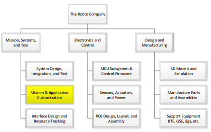
Mission and Application Customization
Programming is not a traditional role for a system engineer, but moved to this level to focus additional attention onto this too often forgotten area.
Task Summary:
- Configure mobile device App
Configure the application software required to remotely control the robot. Control may be done from a PC and/or cell phone (Android or iPhone) application.
If no off-the-shelf application exists to remotely control your robot, it will be necessary to generate this code. If the project falls within this category, it will be useful to have a background in programming in one or more high-level scripting languages like Processing, HTML 5, Java, or MATLAB.
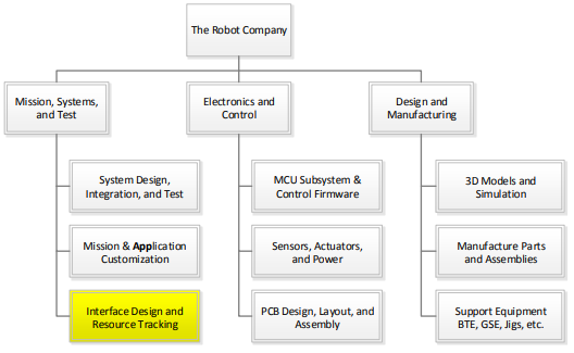
Interface Design and Resource Tracking
System Electronic Interface Design
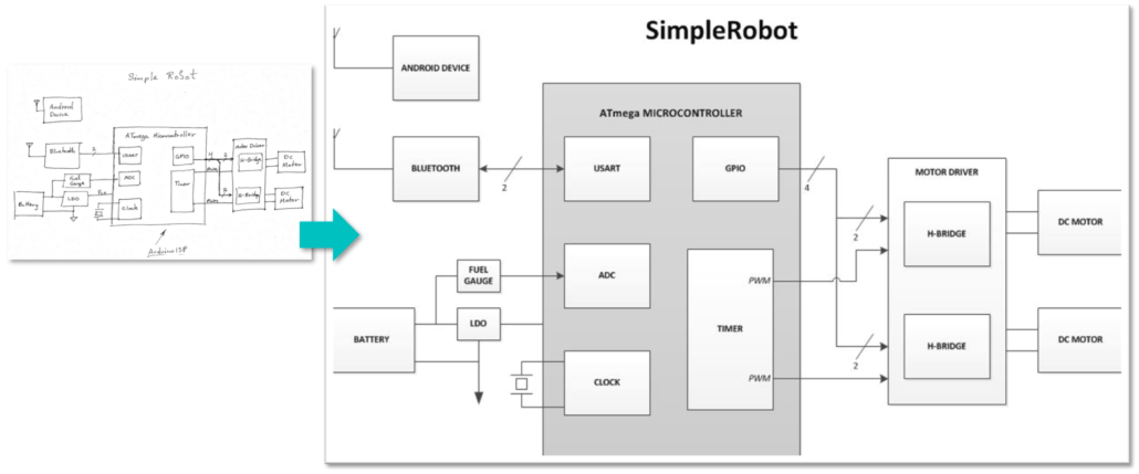
Working with the electronics and control subsystem engineer(s) within each project, document the System Interface Design, which includes the System Block Diagram and Interface Design Matrix.
Power Distribution Strategy
The system engineer, working with the electronics and control and manufacturing engineer, is responsible for defining the power distribution strategy (star and/or multipoint) at the PCB and System level.
Interface Control Document (ICD)
In some cases, projects will be interfacing with another project. Fall ’16 examples include the Prosthetic Arm (Wednesday class) to the Prosthetic Hand (Thursday class) and the Pathfinder Solar Panels (Wednesday class) to the Pathfinder Chassis (Thursday class). For these projects, the systems engineers will work together to write an ICD documenting the electrical connectors and cabling, power, mechanical, and other interfaces associated with the integration of the two projects. Work closely with MST counterpart in other class section, project managers for each project, and president from each class to ensure ICD is being followed. Encourage joint project meetings throughout the life of the project to help maintain communication between groups.
System Resources
Manage all applicable system resources. Resource management typically includes, but is not limited to, mass and power. For example, on a spacecraft, Field-of-View is a resource. When reporting to management, please include margins and contingencies. Margins are applied based on uncertainty in a given line item. Contingency is applied across the resource and is a function of the system resource budget minus the expected value and total margin. Resource reports should be updated on a periodic basis, typically defined by the president. As a rule of thumb, resource reports should be updated every other week and included in the meeting minutes.
Electronics and Control Division
Division Manager
Manage the Electronics and Control Division and associated sections. See the Division Manager section for a general job description. Responsibilities of the engineers within this division are described in the following subsections.
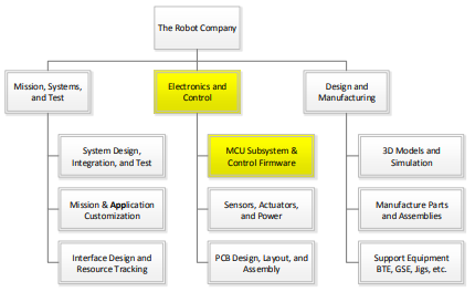
MCU Subsystem and Control Firmware
Task Summary:
- Software Definition
- MCU Communication Firmware
- MCU Subsystem Command and Telemetry Firmware
- MCU Subsystem Control Firmware
Write software subroutines and functions as defined by the software system block diagram. For robots implementing complex motion algorithms, this includes creating a data structure array in SRAM or Flash program memory to define the motion.
Specifically, responsibility of the electronics and control engineer will be to write the firmware required to translate commands into control signals to the actuators, read sensors and translate into data bytes, and implementation of any control algorithms. Communication with the Bluetooth module and decoding of command packets is the responsibility of the systems engineer. The systems engineer is also responsible for collecting and packetizing the data bytes and subsequently sending them to the Bluetooth module.
Qualifications
A background with embedded systems, the Arduino IDE, and the C++ programming language or a desire to learn is a plus.
Software Definition
Develop a software system block diagram. The description of the block diagram should define the function of each module and how they will communicate. For example, number of arguments and their data type, plus return value and data type.
MCU Communication Firmware
The Micro-Controller Unit (MCU) Communication firmware[1] receives and decodes commands and sends telemetry to the Bluetooth device on the robot. The software’s responsibility stops once a command is decoded. For most projects, the E&C engineer will adapt existing C++ programs written within the Arduino IDE for this purpose.
If the project does not fall within the category of having an off-the-shelf application to decode commands and send telemetry, then it would be necessary to have a strong background in programming in C++.
MCU Subsystem Command and Telemetry Firmware
To control actuators and read sensors, software will interface with the peripheral subsystems of the microcontroller including: Timers (e.g., Fast PWM mode), ADC, TWI, SPI, EEPROM, and USART. The Robot Company has developed extensive material on working with the ATmega328P and on how to program its subsystem modules in C++.
MCU Subsystem Control Firmware
The successful candidate(s) will be responsible for the onboard software associated with the stability and tracking control of the robot. Most robots will implement one or more PID control algorithms.
Control input will typically be from an IMU.
For this sub-task a background in embedded systems, C++ programming, and control theory (EE470 and EE471) or a desire to learn is a plus.
[1] Software located in Flash program memory.
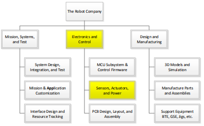
Sensors, Actuators, and Power
Task Summary:
- Define sensor suite
- Define actuators including electromechanical devices and subsystems
- Define communications subsystem
- Define power subsystem
Electronics and control engineer is responsible for selecting and implementing the sensors, actuators and power subsystem to be carried on the robot.
Sensors
Sensors can be as simple as a resistor divider to measure battery voltage and as complex as a SLAM mobile device. In the following paragraphs, sensors typically found on a robot will be discussed.
For measuring target distance, a number of sensors need to be considered including IR, Lidar, Ultrasonic, or camera. Trade-off studies to select a sensor should consider how measurement errors are introduced by the environment (e.g. lighting, reflections, and target surface properties). Also consider the peripheral subsystem required by each sensor type. These may include the ADC or a serial peripheral interface like the I2C, SPI, 1-wire, and USART. A wealth of information can be found on the Internet and here.
For measuring the distance traveled by a robot, consider the addition of a shaft encoder. The trade-off study should investigate traditional (opto and hall effect sensors) and sensorless (commentator and back emf) solutions for measuring the rpms of a DC motor.
For measuring angular rotation and/or velocity to control the stability and tracking of the robot, consider gyro, accelerometer, and magnetometer or some combination of all three incorporated into an Inertial Measurement Unit (IMU). If an IMU is adopted, sensor data may be smoothed using a Complementary or Kalman Filter algorithm. Some commercially available modules incorporate both the IMU and filter.
For measuring battery state, purchase a fuel gauge or simply use a resistor voltage divider.
Actuators
An actuator is defined as any output device. This includes optical devices like LEDs and Lasers. It also includes electromechanical devices like solenoids, servos, and motors.
Electromechanical Devices
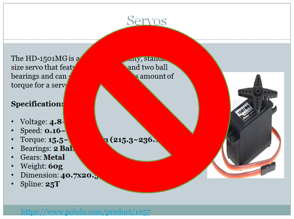
Specification of electromechanical devices, like servos and motors, should be based on quantitative system/subsystem design requirements. From these “specifications”, a trade-off study is typically conducted. The trade-off study usually takes the form of a table where the robot’s desired specification for the electrometrical part is in the first column. The subsequent columns contain the specifications gleaned from the datasheet of candidate commercial off- the-shelf (COTS) parts. The selected parts are then purchased and tested against the original robot specification. These tests should consider static and dynamic loads plus life-cycle testing under worst case load conditions.
Case Study
Up to the Spring 2016 Semester, no SpiderBot has ever completed its mission due to insufficient static and dynamic modeling (back of the envelope and at 3D modeling) at the system level, mass resource management, and life-cycle testing under load conditions.
Electromechanical Subsystems
Electromechanical devices are often combined into subsystems. Robots’ subsystems may include the powertrain and a pan and tilt platform.
Powertrain
The powertrain includes: DC motors and/or servos, transmission (the “gearbox”), and drive electronics (H-Bridge, Shift Register, Power Transistors …). For this subsystem, an educational background in motors and motor control (EE451) or a desire to learn is a plus.
Pan and Tilt Platform
For the robots, the pan and tilt platform carry the mobile device (Android or iPhone). Actuators may include a stepper motor or servo for panning and almost always a servo for tilting.
Communications
For most robots, a Bluetooth module will be incorporated into the design.
Power
The power subsystem may include batteries, charging circuits, DC-to-DC converters, and voltage regulators (linear and LDO). For some robots, consider the addition of solar panels.
DC-to-DC converters may step-down (buck) the input voltage, step-up (boost) the input voltage, and in some cases both. A step-down (buck) converter is also referred to as a UBEC which stands for “Universal Battery Eliminator Circuit”.
Research battery solutions based on quantitative subsystem requirements, resource reports (mass and power), and project requirements (mission duration, safety, etc.). Battery technologies include, but are not limited to, NiCD, Nimh , LiFePO4, and Li-Ion/Polymer. Based on requirements, other power sources may be investigated such as solar.
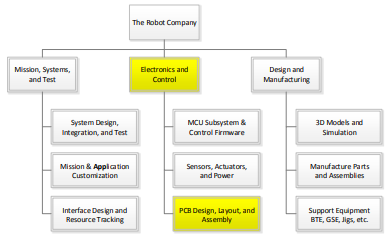
PCB Design
Task Summary:
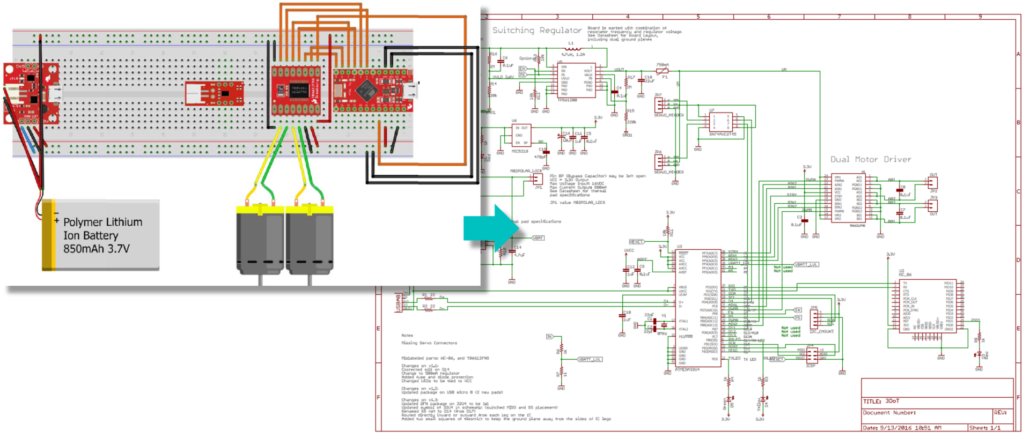
- Working from interface matrix, create a Fritzing diagram
- From fritzing diagram, build breadboard
- Write C++ test software programs both to control the actuators and collect data from the sensors
- Test breadboard
- Using Eagle CAD (schematic capture), create electrical schematic
- Test finished PCB
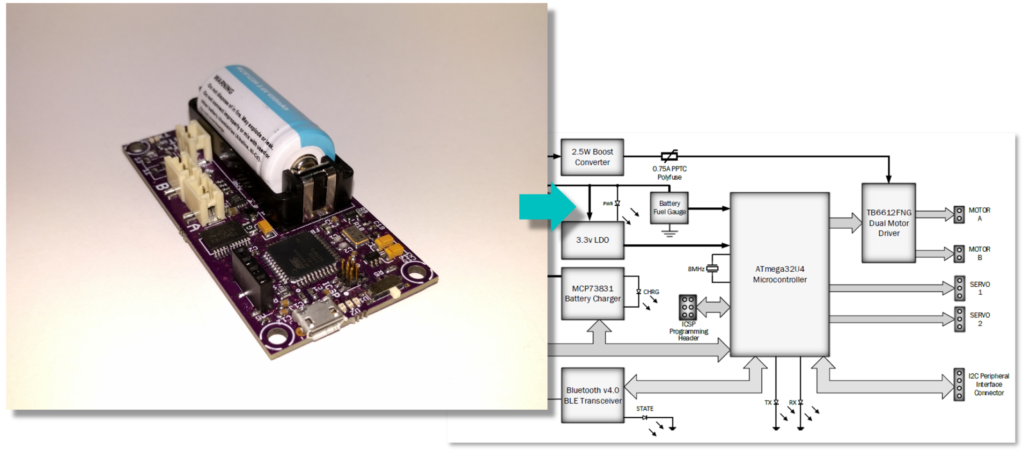
Working from the PBS, System Block Diagram, and Interface Matrix, provided by the system engineer, the electronics and control engineer designs the robot’s Printed Circuit Board (PCB). Working from the provided material, the electronics and control engineer also creates a Fritzing diagram, makes and tests the breadboard, and captures the design, in the form of a schematic, using CAD software (typically Eagle CAD). The manufacturing division is then responsible for laying out the PCB and providing to the Electronics engineer a completely assembled PCB. The electronics and control engineer is then responsible for testing the completed PCB.
PCB Layout and Assembly
Task Summary:
- Layout a PCB with Surface Mount Technology (SMT) discrete components and ICs
- Generate Gerber file and order a SMT solder paste stencil.
- Reflow and hand solder PCB
Working from a schematic, provided by the electronics and control engineer, the power distribution strategy, provided by the system engineer, and the physical constraints of the robot, the manufacturing engineer will design the printed circuit board (PCB), perform ERC and DRC checks, generate the CAM file and upload to a PCB house for fabrication. This process is typically carried out using Eagle CAD.
In addition to the PCB, it will be necessary to purchase the SMT solder paste stencil used for applying paste to the PCB as part of the reflow soldering process. The design of the stencil is generated in Eagle CAD and output as a Gerber file.
Once the PCB and stencil are received, the manufacturing engineer is responsible for reflow soldering of the SMT discrete components and ICs onto the board, as well as hand soldering through-hole discrete components. The board is then given to the electronics and control engineer for testing.
Design and Manufacturing Division
Division Manager
Manage the Design and Manufacturing Section. See the Division Manager section for a general job description. Responsibilities of the engineers within this division are described in the following subsections.
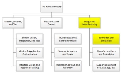
3D Models and Simulation
Task Summary:
- Use CAD/CAE software to design the robot
- Use CAD/CAE software to design the mechanical parts
- Run static and dynamic simulations
The successful candidate(s) will use a solid modeling computer-aided design (CAD) and computer-aided engineering (CAE) software program, typically SolidWorks, to design the mechanical parts, sub-assemblies, and even the robot itself. The overall design must take into consideration all parts manufactured and purchased. The most commonly forgotten parts are the connectors and cabling.
Working with the systems engineer, determine the acceptability of the design by running simulations. These may be in the form of system level animations (e.g., for bipedal robots the walking motion while tracking center of mass), system level load and shear analysis (e.g., for spiders a stress analysis across the body-servo-leg interfaces), and others as seen appropriate.
Qualifications
Work experience with a 3D modeling program or a desire to learn is a plus. Preferred modeling program is Solidworks; however, a working knowledge of Blender, AutoCAD, SketchUp or any other CAD/CAE program will be taken into consideration.
Manufacture Parts and Assemblies
Task Summary:
- Manufacture mechanical parts
- Specify and order off-the-shelf parts
Parts may be fabricated using additive (3D printers), subtractive (CNC, laser cutter, lathe …), or other (vac-u-form, molds …) manufacturing techniques. It is important to work with the manufacturing Division Manager to find the manufacturing technology required for the project.
Off-the-Shelf Parts
Specify and order miscellaneous parts including:
- Fasteners – nuts, bolts, screws, washers…
- Adhesives and Sealants – tape, velcro, zip-ties, O-rings, weather stripping, silicone tube…
- Powertrain Components – belts, gears, bearings…
- Hardware – grommets, brackets…
The customer has a large number of fasteners, powertrain components, and other hardware. Otherwise, purchase such parts from Home Depot and McMaster-Carr among others.
Case Study
The manufacturing engineer of a robot has a friend with a 3D printer. He asks his friend if she will print the parts for their robot. The friend agrees, assuming that the STL files will be provided within a few weeks.
Case 1: Near the end of the semester, the friend receives the STL files and realizes that they simply do not have time to print the parts. What should the manufacturing engineer have done to avoid this problem?
Case 2: The STL files are provided within a few weeks. However, the friend says her 3D printer is broken and she simply does not have time to fix it. Because the engineer now has time to recover from this disaster, instead of running around asking everyone if they have a 3D printer or purchasing time on a 3D printer, he contacts the Division Manager for help. The Division Manager bring up the problem at the next division meeting and another 3D printer is located. This is the strength of the matrix organization!
Test Your Knowledge
Design
- Who is responsible for designing the cabling layout?
- You want to build a pan and tilt platform. Who is responsible for the specification of the servos?
- You want to build a pan and tilt platform. Who is responsible for the design of the brackets to hold the servos?
- Who is responsible for calculating the torque specification for the servo?
- Who is responsible for simulating the pan and tilt platform to insure it will meet FOV requirements.
- Provide one or more examples of a ConOps failure?
Testing
- Who is responsible for designing robot verification tests?
- Which division(s) are involved in testing the robot?
Printed Circuit Board
- Which division(s) are involved in the design, fabrication, and testing of the PCB?
- What part does the System Design engineer play in the design of the PCB?
- Who designs the circuit schematic?
- Who board layout of the Printed Circuit Board (PCB)
- Who is responsible for assembling the PCB?
- Who is responsible for testing the PCB?
Software
- Which division(s) are in involved in software development?
- Your project has decided to develop an iPhone powered spider robot. Who is responsible for customize the Arxterra application to control the spider robot?
- Who is responsible for implementing commands?
- Who is responsible for sending telemetry data packets to the Bluetooth module?
- Who is responsible for writing the firmware to translate sensor inputs into data bytes?
- In which computer can you find the MCU communication firmware?
Other
- Who is responsible for drafting the product breakdown structure (PBS)?
- Your project has decided to use a CNC machine to fabricate a part for your robot. Who should you look to for help?
- Who is ultimately responsible for assigning your grade?
- If you were going to fly a payload on the Space Shuttle, NASA Johnson Spaceflight Center (JSC) reassured you that all surface in the payload bay would be visually clean. Is this a quantitative requirement?
- How often should system resources be updated?
Table of Contents
First Writing Assignment – Job Application Cover Letter and Resume
- Your cover letter along with your resume will help me in assigning company responsibilities. Other direct input for assigning work is welcome.
- One page limit.
- How to write your Cover Letter and Resume
- Resume Format – Write your cover letter in paragraph form as shown in the second figure here. Please do not provide a “functional” cover letter (first example shown).
- Your Cover Letter should tell a story!
- Here are some tips on what Beckman Coulter (Biomedical Engineering) and Google are looking for in your Cover Letter and Resume.
- Finally, some sample EE400D Cover Letter.
- How to Send Me Your Cover Letter and Resume:
- Your cover letter and resume should be in a single PDF document. The name of the document should be your name Joe Smith.pdf.
- Place your Cover Letter with Resume in Beachboard Dropbox.
Job Application Cover Letter
In your job application cover letter please answer the following questions.
- Before you begin be sure you have read our company Job Descriptions. Read our company’s Blog Posts to learn more about each project.
- What Position(s) are you applying for? Start your cover letter with a short sentence that allows our recruiting department to send your cover letter and resume to the correct engineering department(s) for review and consideration.
- Introductory Paragraph(s):
- Next, introduce yourself by starting with the reason (e.g. motivation, goals) you chose electrical engineering.[1]
- Describe some significant engineering experience[2] and any access[3] you may have to resources which match the background requirements on the job posting.
- When describing your engineering experience, include any projects you have built.
4. EE400D Unique Career Path
- How many units are you taking this semester, including 400D? Do you have a job/internship and if yes, how many hours per week do you work?
- What career track would you like to be placed on? – Line (People) Management, Project Management, Technical Excellence
- If you had a choice, what project would you like to be assigned?
- Although the following material is optional, you may want to include it in order to help us place you within the company.
- What technical/project skills would you like to learn?
- What fellow students would you like to work with? Optional
[1] If you are not sure where to start see Appendix A Why Do Students Choose Engineering?
[2] If you do not have any work experience you may include relevant classes.
[3] For example, talent or machines you have access to on campus (e.g., mechanical engineering machine shop, on campus projects, organization like the IEEE, SWE, etc.), at work or home.
Cover Letter Rubric
- Did you follow instructions? For example, did you format and name the document correctly. Is there only one document.
- Strength of the cover letter.
- Glowing platitudes without backup are worse than nothing.
- Your resume is useless if I never read it.
- Grading is harder than normal to better reflect the real world.
- Rule of Thumb… D to C = skip cover letter, B = read resume,
A = job offer w/o even reading resume
- Did you address points in assignment? In are a few questions to ask yourself before you turn in your assignment.
- Did you indicate your career path and project(s) you are interested in working on.
- Did apply for a division with a project option. Did you get the Name of divisions correct?
- Did you define your school and outside workload?
- English Proficiency
Resume
- Create a resume that specifically applies your coursework and/or experience toward the position you are applying for at our company.
- Personalize your resume to the company with a few introductory sentences. Think of your cover letter crystallized into two or three sentences. The company should come away with the idea that this is your dream job and they would be crazy not to hire you.
- One page limit.
- Please see Chapter 3 of Finkelstein on ‘Technical Definitions’ and Chapter 18
- For help, try Resume Builder templates
Appendix A: Why Do Students Choose Engineering?
- Source: Stiquito An Inexpensive Robot by James M. Conrad, North Carolina State University
- Career counselor suggested, based on correct (or incorrect) perceptions of the field.
- A teacher suggested, because the student was good at math and science. (Note: teachers also discourage based on this and perception).
- Second hand knowledge, like from a neighbor, relative, friend, books, newspapers, magazines.
- Direct exposure with the field through work, workshops, class assignments.
Students rarely have direct exposure to engineering.
Table of Contents
The following document paraphrases and quotes material originally contained in the NASA Systems Engineering Handbook NASA-SP-2007-6105-Rev-1 Section 4.0 System Design (page 31)
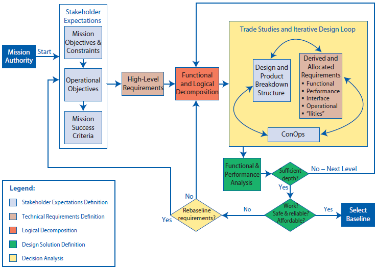
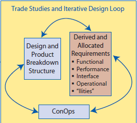
System engineering design is a highly iterative and recursive processes, resulting in a validated set of requirements and a validated design solution that satisfies a set of customer expectations.
- Customer[1] Expectations (Program/Project Objectives and Mission Profile) and Constraints (Stakeholders, Institutional, Professional, etc.).
- High Level Functional Requirements[2] (Level 1 Program/Project)
- Functional and Logical decompositions (Project WBS)
- Trade Studies and Iterative Design Loop
- Form Creative Design Solution (System PBS)
- Define Level 2 System and Subsystem Performance Requirements
- Make Hardware and/or Software Model(s) and Perform Experiments
- Organize and Analyze Data
- Does Functional & Performance Analysis show design will meet Functional Design and concept of operations (ConOps) Requirements?
- If additional detail need, Repeat Process
- Select a preferred design
- Does the system work[3] (functional and performance)?
- Is the system achievable within cost and schedule and other constraints?
- If the answer is no, reenter design loop (Step 4), reorganize project (Step 3), or adjust Customer’s Expectations and Constraints (Step 1) and start again.
- Preparing presentations (PDR and CDR)
- Communicate Results (PDR and CDR)
- Reports, plans, and specifications. (Project Planning)
- Implement, Verify, and Validate the design. (Project Implementation)
The Iterative Nature of the System Design Process
After Mission Authorization (i.e. funding), the process Starts with a study team collecting and clarifying the Customer’s Expectations, including the program objectives, constraints, design drivers, mission profile[2], and criteria for defining mission success.
 From the customer’s expectations high-level requirements are defined. These high-level requirements drive an iterative design loop where (1) creative “strawman” architecture/designs, (2) the concept of operations (ConOps), and (3) derived system and subsystem requirements are developed.
This process will require iterations and design decisions to achieve consistency (design loop blocks 1 – 3). Once consistency is achieved, analyses allows the project team to validate the design against the customer’s expectations. A simplified validation asks the questions:
- Does the system work (functional and performance)?
- Is the system achievable within cost and schedule constraints? [3]
The output of this step will typically result in modification of the customer’s expectations and the process starts again. This process continues until the system—architecture, mission profile, and requirements and stakeholder expectations achieve consistency.
The number of iterations must be sufficient to allow analytical verification of the design to the requirements.
The design process is hierarchical and recursive by nature with the same process applied to the next level down in the program – one person’s subsystem is another person’s project.
System Design Keys
- Successfully understanding and translation of the customer’s expectations into clear unambiguous quantitative, verifiable, and realizable program requirements
- Complete and thorough requirements traceability (including requirement flow-down)
- Document all decisions made during the development of the original design concept[4].
- Visualization of the product in use (ConOps) looking for missed level 1 requirements. Rapid Prototyping also helps us discover missing level 1 requirements (ex. ShopVac).
- Design validation is a continuing recursive and iterative process occurring over the entire life cycle of the product
| Note: It is extremely important to involve the customer in all phases of a project. Such involvement should be built in as a self-correcting feedback loop that will significantly enhance the chances of mission success. Involving customer in a project builds confidence in the end product and serves as a validation and acceptance with the target audience. |
ConOps Examples
Remember, validation occurs over the life of the product (from concept to retirement).
Design faults discovered before the operational phase of the project.
- On the prosthetic arm project, conOps showed that we had failed to conceptualize the soldier in McDonalds. Specifically, in appearance and the potential noise generated by the system. In both cases, unwanted attention of fellow customers would have been be placed on the soldier.
- On the solar panel project, conOps showed that we had failed to conceptualize operation of the rover remotely, in the desert or ultimately on Mars. Once discovered telemetry requirements were added to the project.
Design faults discovered during the operational phase of the project.
- After successful verification of the Pick and Place machine we tried to put it in a cabinet. Clearly, we did not conceptualize this step in the life-cycle of the product. All future projects now include this customer requirement.
- … it emerged that the design of Type 45 destroyers have faulty engines unable to operate continuously in warm waters. “The UK’s enduring presence in the Gulf should have made it a key requirement for the engines. The fact that it was not was an inexcusable failing and one which must not be repeated,” the MPs’ report said. Source: BBC “Royal Navy ‘woefully low’ on warships”
Customer Expectations (Project Objectives and Mission Profile)
Sponsor presents Program and/or Mission Objectives
- These are not requirements, but rather a statement of a problem to be solved. They may be qualitative in nature.
High Level Requirements (Level 1 Program/Project)
Reference: NASA Systems Engineering Handbook Section 4.2 Technical Requirements Definition Start (page 40) and Appendix C page A: 279
- Translate Program and/or Mission Objectives into Level 1 Program/Project Requirements.
- Work with and get the sponsors concurrence that these meet their Program and/or Mission Objectives.
- It is important to document all decisions made during these early phases of the project. Include links to source material and how decisions were made.
- Were the equations used to calculate a requirement provided and are the answers correct?
- Close attention to this process is the difference between the customer saying “you said” and your company paying to correct the problem within the agreed upon schedule, versus you telling the customer your new requirement is out-of-scope and your customer paying the increased cost with attendant schedule delay[1].
Form Creative Solutions
The word “creative” appears less than a half dozen times in the 360 page NASA Systems Engineering Handbook. I will therefore rely on outside sources.
Logical decompositions (Level 2 Systems)
The following document paraphrases and quotes material originally contained in the NASA Systems Engineering Handbook NASA-SP-2007-6105-Rev-1 Section 4.3 Logical Decomposition (page 49)
“Logical Decomposition is the process for creating the detailed functional requirements that enable NASA programs and projects to meet the stakeholder expectations. This process identifies the “what” that must be achieved by the system at each level to enable a successful project. Logical decomposition utilizes functional analysis to create a system architecture and to decompose top-level (or parent) requirements and allocate them down to the lowest desired levels of the project.”
Design solutions – Experiments and Modeling (Level 2 Subsystems)
TBD
[1] For more on this subject see Week 3 “Requirements” document on page 10.
Program Design Verification and Validation
Source: NASA Systems Engineering Handbook NASA-SP-2007-6105-Rev-1, Section 5.3 Product Verification
While the approaches taken to verify and validate a design may be similar, the reason behind the tests are different. Verification tests confirm that Project Objectives for the design (ex. the robot) as defined by its level 1 and level 2 design requirements are met. Validation tests confirm that the design can accomplish its mission. For our robots this is defined by the Mission Profile.
|
Here is a simple way to understand and remember the difference between verification and validation.
Verification – was the product built right?
Validation – was the right product built?
|
Like the design process, verification and validation are hierarchical by nature with the same process applied to the next level down in the program – one person’s subsystem is another person’s project.
Requirements Verification Matrix
Source: NASA Systems Engineering Handbook NASA-SP-2007-6105-Rev-1, Appendix D: Requirements Verification Matrix
When developing requirements, it is important to identify an approach for verifying the requirements. The requirement verification matrix defines how all design requirements are verified. The matrix should identify each requirement by a unique identifier and be definitive as to the source. The example shown provides the minimum information that should be included in the verification matrix.
Table D‑1 Simplified Requirements Verification Matrix
| Requirement No. | Paragraph | Shall Statement | Verification Success Criteria | Verification Method | Results | PASS / FAIL |
| P-1 | 3.2.1.1 Capability: Support Uplinked Data (LDR) | System X shall provide a max. ground-to-station uplink of… | 1. System X locks to forward link at the min and max data rate tolerances 2. System X locks to the forward link at the min and max operating frequency tolerances | Test | ||
| P-i | Other paragraphs | Other “shalls”in PTRS | Other criteria | xxx | ||
| S-i or other unique designator | Other paragraphs | Other “shalls”in specs, ICDs, etc. | Other criteria | xxx |
- Unique identifier for each System X requirement. The identifier should indicate the document the System X requirement is contained within. If more than 1 include a key (P = PDR, C = CDR)
- Paragraph number of the System X requirement.
- Summary Text (within reason) of the System X requirement, i.e., the “shall.”
- Success criteria for the System X requirement.
- Verification method for the System X requirement (analysis, inspection, demonstration, or test). If not verified in ECS-316 then indicate facility or laboratory used to perform the verification and validation (home, ECS-315).
- Indicate documents that contain the objective evidence that requirement was satisfied
- Simple PASS/FAIL
Program Validation
Source: NASA Systems Engineering Handbook NASA-SP-2007-6105-Rev-1, Appendix E: Creating the Validation Plan (Including Validation Requirements Matrix)
When developing a design, it is important to identify a validation approach for demonstrating that the system (robot) can accomplish its intended mission. Validation testing is typically defined and conducted by the customer.
To simplify the course, a single validation grade will be assigned at the end of the mission.
Terminology
High-Level Program/Project Requirements and Expectations: These would be the top-level requirements and expectations (e.g., needs, wants, desires, capabilities, constraints, and external interfaces) for the product(s) to be developed. (Section 4.1.1.3)
ConOps: Concept of Operations – This describes how the system will be operated during the life-cycle phases to meet stakeholder expectations. It describes the system characteristics from an operational perspective and helps facilitate an understanding of the system goals. (Section 4.1.1.3)
SE: Systems Engineering is the art and science of developing an operable system capable of meeting requirements within often opposed constraints. Systems engineering is a holistic, integrative discipline, wherein the contributions of structural engineers, electrical engineers, mechanism designers, power engineers, human factors engineers, and many more disciplines are evaluated and balanced, one against another, to produce a coherent whole that is not dominated by the perspective of a single discipline. (Section 2.0 Fundamentals of System Engineering)
Lecture Notes
Table of Contents
Reading
- NASA Systems Engineering Handbook NASA-SP-2007-6105-Rev-1 Appendix C: How to Write a Good Requirement, Use of Correct Terms
- NASA Systems Engineering Handbook NASA-SP-2007-6105-Rev-1 Appendix C: How to Write a Good Requirement, Requirements Validation Checklist, Clarity
- NASA Systems Engineering Handbook NASA-SP-2007-6105-Rev-1 Section 4.2 Technical Requirements Definition Start (page 40)
- Department of Chemical Engineering, University of Michigan, Ann Arbor, Chapter 5 “Problem Definition Techniques”
The Systems Engineering Method
- Customer[1] Expectations (Project Objectives and Mission Profile)
- High Level Requirements (Level 1 Program/Project)
- Functional and Logical decompositions (Project WBS)[2]
- Trade Studies and Iterative Design Loop
- Form Creative Design Solution (System PBS)
- Define Level 2 System and Subsystem Requirements
- Make Hardware and/or Software Model(s) and Perform Experiments
- Organize and Analyze Data
- Does Functional & Performance Analysis show design will meet Functional Design and concept of operations (ConOps) Requirements?
- If additional detail need, Repeat Process
- Select a preferred design
- Does the system work[3] (performance)?
- Is the system achievable within cost and schedule constraints?
- If the answer is no, adjust Customer’s Expectations (Step 1) and start again.
- Communicate Results (PDR and CDR)
- Preparing presentations (PDR and CDR)
- Reports, plans, and specifications. (Project Planning)
- Implement the design. (Project Implementation)
The System Engineering Design Method
Customer Expectations (Project Objectives and Mission Profile)
After Mission Authorization (i.e. funding), the process Starts with a study team collecting and clarifying the Customer’s Expectations (The Problem Statement), including the program objectives, constraints, design drivers, mission profile[1], and criteria for defining mission success.
- Include information on what you are to solve, and consider why you need to solve this problem.
- A conversation with Elon Musk about Starship from 4:50 to 6:21.
- Case Study – 1st Iteration
- Problem: People are being injured and dying in traffic accidents.
- Customer Objective: Decrease the number of traffic accidents
- Social Engineering Solution: Roll out a “Drive Safely” campaign with better driver education and traffic enforcement
[1] I will use the term Mission Profile in place of Operational Objectives
Customer Expectations May Change
As we have seen, the statement of the Customer’s Expectations may be modified as objectives are translated into requirements and the nature of the real problem is better understood.
After each iteration, make sure you are proceeding to solve the real problem as opposed to the perceived problem.
- Case Study – 2nd Iteration
- Problem: People are being injured and dying in traffic accidents.
- Customer Objective: Decrease the number of (injuries due to) traffic accidents
- Engineering Solution: Design a safer vehicle and roadways
Duncker Diagrams
- As you explore the problem by translating into requirements, a step which includes design trade-off studies, simulation, modeling, experiments, and rapid prototyping; you may also want to first apply the Duncker Diagram.
- Case Study – Duncker Diagram
- Problem: People are being injured and dying in traffic accidents.
- Achieve Desired State: Decrease the number of traffic accidents
- Path 1: Driver education
- Solution 1a: Roll out a “Drive Safely” campaign
- Path 2: Traffic enforcement
- Solution 2a: Hire more policemen
- Path 3: Autonomous Vehicles
- Ok not to Achieve Desired State: Do NOT decrease the number of traffic accidents
- Path 1: Design a safer vehicle
- Solution 1: Air Bags
- Solution 2: Impact crumple zones
-
- Path 2: Design safer roadways
- Solution 1 – 7: Roadway Engineering Design Strategies To Make Roads Safer For Drivers
To Market, To Market

The Situation: Toasty O’s was one of the hottest selling cereals when it first came on the market. However, after several months, sales dropped. The consumer survey department was able to identify that customer dissatisfaction, as expressed in terms of taste, was related to the age of the cereal. Consequently, management determined that they must streamline the production process to get the cereal on the store shelves faster, thus ensuring a fresher product. Engineering had quite a time with this problem – there wasn’t much slack time that could be removed from the process to accomplish the goal.
Of the steps required to get the product on the shelves (manufacturing, packaging, storage, and shipping) manufacturing and packaging were the fastest so plans for building plants closer to the major markets were considered as was trying to add more trucks to get the cereal to market faster.

Sales of Toasty O’s are dropping. Consumer surveys have indicated dissatisfaction with a stale taste.
Perceived Mission Objective (The Problem):
“Streamline the production process to get the cereal on the store shelves faster, thus ensuring a fresher product.”
Second Perceived Objective:
Get the Cereal to Market Faster
Duncker Diagram

Original Mission Statement
Get cereal to market faster.
The real problem was that the cereal was not staying fresh long enough, not that it wasn’t getting to market fast enough.
New Mission Statement
Make Toasty O’s boxes tighter and determine appropriate additive to slow down the spoiling reaction.
Table of Contents
Searching for Creative Solutions
Once you have Identifying the real problem and gathered needed Information it is time to search for “original” creative solutions.
- Here are several techniques to help you and your team produce original creative ideas.
- Ideas may come from creativity, a subconscious effort, or innovation, a conscious effort.
- The objective is to break the set patterns of thought that everyone develops (i.e., team’s thinking tends to fall into ruts).

Brainstorming (or Brainwriting) Approach
- Brainstorming versus Brainwriting
- All ideas are encouraged.
- Write down as many ideas as possible
- After a break, combine and improve ideas.
- Delay judgment and evaluation of ideas until end…
- Comments that Reduce Brainstorming to Braindrizzling
| That won’t work | It’s against our policy |
| That’s too radical | We haven’t done it that way before |
| It’s not our job | That’s too expensive |
| We don’t have enough time | That’s not practical |
| That’s to much hassle | We can’t solve this problem |
Brainstorm Checklist
| Before | During | After |
| Who is the facilitator and the participants/team? | Review brainstorming approach and rules. | Is another meeting required to continue exploring the best ideas? |
| Participant group is small, focused, and represent a cross-section of the disciplines and/or stakeholders. | Is the objective and problem clearly defined? | No – Document |
| Facilitator writes a clear definition of the objective along with a short brief of the problem and sends to the team. | Have first principles been identified. | Yes – Rinse and Repeat |
| Have participants done their homework/research? | Explore ideas! Never reject or write down anyones idea. Always write it down after multiple team members have contributed to the evolution of the idea. Have fun. | |
| Conference room and tools (whiteboard, projector, easel, etc.) in place | Determine the next step. |
The Fishbone Diagram
Methodology
- List the major attributes or properties of a product, object, or idea – The fish bones
- For each attribute, Brainstorm how each of the attributes could be changed.
Example
How can we improve the design of a cell phone?
| Attribute | Brainstorm |
| Color could be … | Be Any color Be transparent Utilize designs such as plaid Have a personalized design (skinit) |
| Material could be … | Metal Glass (Mac Funamizu) Wood (NTT Docomo) Hard rubber (Lux) |
| Input device could be … | 10-push-button design Could be lever system Could use abacus-type system Could be push buttons arranged in a line |
| Make the shape … | Square Round Oval |
Lateral Thinking
Edward de Bono developed the lateral thinking techniques of random stimulation and using other people’s views to generate ideas during brainstorming. Lateral thinking provides new ways to come at a problem and get “unstuck.” We will look at two:
- Forced Relationship Technique
- Different Point of View
Forced Relationship Technique
Methodology
- Take a fixed thing, such as the product or some idea related to the product
- Force it to take on the attributes of another unrelated thing.
- Brainstorm
Pro-Tip: Try this Random Noun Generator
Example – Weed Cutter
The weed cutter will be the forced object. Suppose we randomly choose an automobile wheel as the other element. Some of the ideas that may occur based upon the automobile wheel are:
| A weed cutter that rolls. |  |
| A round weed cutter. | |
| A rubber weed cutter. |  |
| A weed cutter that has spokes. |  |
| A weed cutter that has brakes. |  |
Different Point of View
People sometimes stretch their minds by adopting different points of view.
- Imagine yourself in the future ; “What are the characteristics of an ideal solution?” even if not technically feasible today.
- Imagine a similar problem located on a strange planet or in free fall.
- Try to identify with the stone that is to be crushed, or the fruit that is going to be peeled.
- Pretend that common materials or components are not available or that certain exceptional ones are.
- Try to project how nature would do it.
- The methods are endless.
The rain to the wind said,
‘You push and I’ll pelt.’
They so smote the garden bed
That the flowers actually knelt,
And lay lodged–though not dead.
I know how the flowers felt.
Overcoming Obstacles to Creative Thinking
 Here are a few more specific actions and attitudes that can be employed to overcome obstacles to creative thinking:
- Avoid placing unnecessary constraints on the problem being solved.
- Search for different ways to view the problem, avoiding preconceived beliefs and stereotypical thinking.
- Recognize that there are non-engineering solutions to many problems. Consider approaches that other disciplines might use.
- Look for relationships that are remote and solutions that are unusual and nontraditional.
- Most creative thought involves putting experiences and thoughts into new patterns and arrangements.
- Divide complex problems into manageable parts and concentrate on solving one part at a time.
- Allow time for incubation, after periods of intensive concentration – sleep on it
- Be open to a variety of problem-solving strategies.
Reference Material
- Introduction to Engineering Design and problem Solving, The Summer Institute for Engineering and Technology Education, University of Arkansas 1995.
- University of Arkansas – A Collection of Engineering Design Problems [2009 Edition] This document also introduces “The Design Loop”
- Teehan+Lax-Brainstorming-Checklist
- University of Michigan – Strategies for Creative Problem Solving
- Download and install first module – Brainstorming
- University Of Michigan Chapter 4 – The First Four Steps
- University Of Michigan Chapter 5 – Problem Definition Techniques
- University Of Michigan Chapter 6 – Breaking Down the Barriers to Generating Ideas
- University Of Michigan Chapter 7 – Generating Solutions (a lot of branches from this material)
- University Of Michigan Chapter 8 – Deciding the Course of Action
- University Of Michigan Chapter 9 – Implementing the Solutions
Types of Requirements
Table of Contents
Reading
- NASA System Engineering Handbook NASA-SP-2007-6105-Rev-1, Section 4.2.2.1 Types of Requirements
- AcqNotes Requirements Development – Requirement Types
Requirement Types
Functional requirements
Functional requirements define what functions need to be performed to accomplish the objectives. For example “The Thrust Vector Controller (TVC) shall provide vehicle control about the pitch and yaw axes.” This statement describes a high-level function that the TVC must perform. The technical team needs to transform this statement into a set of design-to functional and performance requirements. [1]
Performance requirements
Performance requirements define how well the system needs to perform the functions. Here are the performance requirements associated with the functional requirements example. [2]
• The TVC shall gimbal the engine a maximum of 9 degrees, ± 0.1 degree.
• The TVC shall gimbal the engine at a maximum rate of 5 degrees/second ± 0.3 degrees/second.
• The TVC shall provide a force of 40,000 pounds, ± 500 pounds.
• The TVC shall have a frequency response of 20 Hz, ± 0.1 Hz.
Be careful not to make performance requirements too restrictive. For example, for a system that must be able to run on rechargeable batteries, if the performance requirements specify that the time to recharge should be less than 3 hours when a 12-hour recharge time would be sufficient, potential design solutions are eliminated. In the same sense, if the performance requirements specify that a weight must be within ±0.5 kg, when ±2.5 kg is sufficient, metrology cost will increase without adding value to the product.
Derived Requirements
Requirements that are implied but not explicitly stated or transformed from higher-level requirement. For example, a requirement for long range or high speed may result in a design requirement for low weight.
Requirements arising from constraints, consideration of issues implied but not explicitly stated in higher-level requirements, factors introduced by the selected architecture, and the design. [3] For example, a requirement for long range or high speed may result in a design requirement for low weight. [4]
Allocated Requirements
A requirement that is established by dividing or otherwise allocating a high-level requirement into multiple lower-level requirements. Example: A 100-pound item that consists of two subsystems might result in weight requirements of 70 pounds and 30 pounds for the two lower-level items. By definition, these are interface requirements and may include mass properties, structural/mechanical, fluid, electrical (power), electronic (signal), software and data, environment (ex. dimensions, center-of-mass, field-of-view, stiffness), electromagnetic effects (electromagnetic compatibility, electromagnetic interference), to name a few. [5]
Specifications and Design Requirements
The “build to,” “code to,” and “buy to” requirements for products and “how to execute” requirements for processes expressed in technical data packages and technical manuals. [6] All applicable standards must be referenced or included in the product specifications.
A specification provides sufficient depth, guidance, and constraints to build/purchase the design.
Technical Requirements
Technical Requirements are the customer and stakeholder needs that have been translated into a complete set of validated requirements for the system, including all interface requirements. [7]
- Interface
- The external interface forming the boundary between the product and the rest of the world.
- Types of interfaces include: operational command and control, computer to computer, mechanical, electrical, thermal, and data.
- Plus
- Constraints… Environmental, Reliability, Safety, Programmatic (including cost, schedule), Institutional
Endnote
Requirement Flowdown
In this section, I will look at how these requirement types fit within the temporal and hierarchical structure (Figure 1) of a NASA flight project.
Once the customer (e.g., NASA HQ) receives “Mission Authority” (funding), mission objectives and requirements are finalized and given to the implementing organization (e.g., JPL). Along with mission definition, the implementing organization is presented with programmatic constrains, including cost, schedule, and if applicable mission classification.
The implementing organization then translates these mission performance requirements and constants into project/system functional requirements. To these functional requirements, the implementing organization adds institutional constraints, assumption, environmental, and other design requirements and guidelines to a depth sufficient to write project/system performance requirements.
These project/system performance requirements are then further decomposed and allocated among the elements and subsystems. This decomposition and allocation process continues until a complete set of design-to requirements is achieved. At each level of decomposition (system, subsystem, component, etc.), the total set of derived requirements must be validated against the stakeholder expectations or higher level parent requirements before proceeding to the next level of decomposition.
Table of Contents
Engineering Design
Engineering design is a process of devising a system, component, or process to meet desired needs and specifications within constraints. It is an iterative, creative, decision-making process in which the basic sciences, mathematics, and engineering sciences are applied to convert resources into solutions. Engineering design involves identifying opportunities, developing requirements, performing analysis and synthesis, generating multiple solutions, evaluating solutions against requirements, considering risks, and making trade- offs, for the purpose of obtaining a high-quality solution under the given circumstances. For illustrative purposes only, examples of possible constraints include accessibility, aesthetics, codes, constructability, cost, ergonomics, extensibility, functionality, interoperability, legal considerations, maintainability, manufacturability, marketability, policy, regulations, schedule, standards, sustainability, or usability.
– ABET Glossary F’18
Terminology
Constraint
A constraint is a condition that must be met. Sometimes a constraint is dictated by external factors such as orbital mechanics (schedule) or the state of technology; sometimes constraints are the result of the overall budget environment. It is important to document the constraints and assumptions along with the mission objectives. [1]
In this definition we see a clear delineation between constraints (cost and schedule) and performance (mission objectives). [3]
Constraints may also take the form of compliance with standards, codes, and technical regulations. These evolve from the concept of interoperability.
Interoperability
Interoperability is a characteristic of a product or system, whose interfaces are completely understood, to work with other products or systems, present or future, in either implementation or access, without any restrictions. [4]
Within the context of the course we will limit the scope of interoperability to its original definition; in other words, information technology and systems engineering applications. A broader definition takes into account social, political, and organizational factors that impact system to system performance.
In the Figure 1 we see the term “interoperability” within the context of “compatibility” and “de facto standard. Historically, interoperability is the codification of a de facto standard by a recognized professional organization, like the IEEE .
With respect to the Open Systems Interconnection model (OSI model) [5], interoperability may be present at each layer. Examples at higher layers include XML and SQL. At lower layers we have ASCII and Unicode. At the hardware (physical) layer we have serial communication protocols like the I2C serial peripheral interface (SPI), universal asynchronous receiver-transmitter (UART); all supported by the 3DoT board.
Standards
Standards provide a proven basis for establishing common technical requirements across a program or project to avoid incompatibilities [2] and may in some instances actually lower implementation cost.
This most common example of standards is in weights, measures, and monetary.
Codes
Laws that specify minimum standards to protect public safety and health such as codes for construction of buildings. Initially voluntary and consensus standards, later incorporated into codes. Codes which apply to product development and workmanship are included in the product specifications.
Technical Regulation
A technical regulation is a Government document that defines product characteristics or their related processes and production methods, including the applicable administrative provisions, with which compliance is mandatory. [7]
The difference between standards, codes, and technical regulations lies in compliance. While compliance with standards is voluntary, codes and technical regulations are by nature mandatory.
Organizations that Define Standards, Codes, and Regulations
Standards Organizations
Following is a small representative sample of organizations that establish standards.
- ASTM (American Society for Testing and Materials)
- IEEE (Institute of Electrical and Electronics Engineers)
- ASME (The American Society of Mechanical Engineers)
- ANSI (American National Standards Institute)
- NASA Standards
- ISO (International Organization for Standardization)
Codes and Regulatory Organizations
Here are two examples of organizations that establish codes and regulations.
- United States Department of Justice Civil Rights Division, Americans with Disability Act (ADA)
- In Canada, national construction codes are published by the National Research Council of Canada.
References/Resources
7) WTO: Non-Tariff Measures, Technical Barriers to Trade, Part 3: Difference between standards and technical regulations
Program Constraints
From Constraints to Programmatic Requirements
A critical part of the design process is an early understanding of the overall real-world constraints placed on the program. These constraints may come from the customer “programmatic” or the implementing organization “institutional.” The specific constraints applied to the program are a subset of the constraints, standards, codes, and regulations under which the customer or implementing organization operate. These constraints are typically not able to be changed based on trade off analyses. Once this subset is defined, they become programmatic requirements. Once these constraints are defined requirements can be further defined by establishing performance criteria. The performance is expressed as the quantitative part of the requirement to indicate how well each product function is expected to be accomplished. The rationale should be kept up to date. Often the reason for the requirement is not obvious, and it may be lost if not recorded as the requirement is being documented. The reason may point to a constraint or concept.
This flow-down of customer and institutional constraints into requirements is illustrated in Figure 2.
As part of your final report you will need to review and show compliance with constraints on the project imposed by The Robot Company (i.e., CSULB) and Project Stakeholders.
Project/Economic
Subcategories: Cost, Extensibility, Interoperability, Maintainability, Quality, Marketability, and Schedule
All 3DoT robots shall be constrained to a a Cost not to exceed $250.
All project Schedules shall be constrained to a completion date of Tuesday December 18, 2018. Project completion includes documentation and materials purchased by or loaned to the project.
One of the Economic Factors affecting our robots are return rates. To demonstrate the durability and child friendliness of our robot a simple drop test from 1.4 meter shall be performed. The height is defined by the average height of an average 11 year old girl.
Extensibility is designed into the 3DoT board by way of one 8-pin 100 mil connector located on the front of the board and two 8-pin 100 mil connectors located on the top of the board. By plugging shields into these connectors, the 3DoT board can support a diverse set of robots. All robots shall contain one or more custom designed 3DoT shields. The 3DoT shield(s) incorporating interface electronics between the 3DoT board and sensors and/or actuators unique to the robot. Surface Mount Technology (SMT) will be employed unless a waiver for through-hole parts is granted.
Maintainability: Disassemble and Reassemble of the robot shall be constrained to less than 20 minutes (10 + 10 minutes). Disassembly: The 3Dot board is clear of all other electronic and mechanical subassemblies. All electronic and mechanical subassemblies and associated connectors, sensors, and actuators including motors are disconnected. A functional test of the robot is conducted after reassembly to confirm its functionality. All project may reference a cable tree as well as an assembly diagram as necessary. This requirement is demonstrated/verified on the last day of the schedule. Projects may request a waiver with justification.
Social and Ethical
Subcategories: Accessibility, Aesthetics, and Usability
Accessibility by the blind and Marketability of the robots shall be implemented/enhanced by a speaker. The speaker shall generate sound effect consistent with the type of the robot. For example, the Goliath tank would make “track” sounds, the AT-ST sound effects would mimic their Star Wars antecedent.
To enhance Aesthetics, the robot shall be designed in such a way that there are no dangling or exposed wires. Compliance with this requirement, includes the use of keyed and clearly labeled connectors between all electronic and electromechanical components. Do not use jumper wires; ribbon cables are preferred but not required. Loose wires should be contained using spaghetti tubing (not shrink tubing). For 3DoT projects consider using terminal blocks, 100 mil contact pins and headers, 2.0mm PH series JST connectors, and barrel connectors. Handling Precaution for Terminal and Connector will be in compliance with JST documentation.
To enhance Aesthetics, the form factor of a robot modeled on a real or fictitious robot shall be constrained by the original. For example, Goliath should be a scale model of the real Goliath 302 tank. Projects may request a waiver with justification.
Usability of the robots shall be enhanced by adding autonomous functions and/or by use of the Arxterra phone and control panel application as dictated by the assigned mission.
Manufacturability
Subcategories: Constructability, Size, Weight, and Power (SWAP)
Constructability of 3DoT robots shall be documented at the CDR and approved by the president of the TRC robot company. Constraints imposed by this requirement include the use of bushing or bearings in all moving and rotating parts. Interlocking Hinges with latching mechanism. No gaps greater than 1 millimeter, and immediate access to all external connectors (USB, switches).
Manufacturability of 3D printed robots shall be demonstrated by compliance with the 3/3/3 rule. Specifically, total print of a robot is constrained to 9 hours, with no single print taking longer than 3 hours. Projects may request a waiver with justification. This requirement is waived for 3D prints provided by the library’s Innovation Space. In its place, all 3D prints provided by the library’s Innovation Space should minimize the number of files to be printed. Justification should be provided if more than one (1) file is required.
The Size of the electronics enclosure, shall be constrained to be no greater than the 3DoT board, 3DoT shield(s), and associated mounting hardware.
Power to all 3D robots shall be provided by the 3.7V RCR123A battery included with the 3DoT board or use of the external battery 2.0mm PH series JST connector located on the 3DoT board. The RCR123A is a Lithium Polymer LiPo battery. All Safety regulations as defined in Section 4.3 Hazards and Failure Analysis of this document shall apply to the shipping, handling, storage, and disposal of LiPo batteries.
Power to all 3DoT robots shall be provided by the 3.7V 750 mA 2.775Wh Li-Ion battery included with the 3DoT board or use of the external battery 2.0mm PH series JST connector located on the 3DoT board. Compliance will be provided in Section 3.5 Power in the Final Blog Post. Measured current shall have a margin of 5%. Contingency shall be based on measured current, plus margins associated with each line item, minus 750 mA with an assumed depth of discharge of 80% grams (i.e., 600 mA).
Back of the envelope calculations and experiments shall be conducted to set the diameter of Power carrying wires. Follow the American Wire Gauge (AWG) standard when defining the diameter of power-carrying wires. This work to be completed and documented by the CDR.
Environmental Health and Safety (EH&S) Standards
Subcategories: Environmental Standards, Sustainability, Toxic waste (Solar panels), Health and Safety, Ergonomics
All standards, codes, and regulations as defined in the “Engineering Standards and Constraints” Section of this document shall apply.
All Lithium (Li-ion, Li-polymer) batteries shall be purchased with and stored, when not in use, in a fire and explosion proof battery bag.
Robot Interoperabilty
All 3DoT robots shall incorporate the 3DoT v9.05 or later series of boards.
Software shall be written in the Arduino De facto Standard scripting language and/or using the GCC C++ programming language, which is implements the ISO C++ standard (ISO/IEC 14882:1998) published in 1998, and the 2011 and 2014 revisions. Required exceptions to this standard can be found here.
All 3DoT robots shall be in compliance with the 3DoT Command and Telemetry Packet specification.
All 3DoT robots shall be controlled via Bluetooth 4.0 in compliance with the Bluetooth Special Interest Group (SIG) Standard (supersedes IEEE 802.15.1).
Allocated Requirements / System Resource Reports
Allocated requirements, also known as resource reports, are written and tracked by the System Engineer. The types of resource reports are based on the project. For example, power allocation/estimate for each subsystem module of a spacecraft would be important, while a more loose tracking for a toaster would be in order. Each resource should have a margin attached to it based on the uncertainty in the estimate. It should also show contingency, where contingency is defined as the project allocation minus the estimate plus total margin. Project allocations shall be based on a model (back-of-the-envelope, simulation, prototype, etc.) or other rationality (e.g., similarity to a related product).
Section shows updated useable capacity of the power source selected for the project. Typically represented in a tabulated format, it should include an expected current drawn, measured current drawn, percent uncertainty, and margin for each resource consuming power. Lastly, it should contain total expected current, total margins, project allocation, and contingency clearly showing the power source selected will support the project.
This section is comparable to the previous power allocation section however, dedicated to the updated mass of the project. Also in a tabulated format, it should contain the expected weight, measured weight, percent uncertainty, and margin for each respective resource being used in the project. Lastly, it should contain total expected weight, total margins, project allocation, and contingency.
Any other resources tracked by the system engineer. For example, 3DoT projects using a 3D printer have an 9 hr. (3/3/3) resource requirement that must be tracked.
Cost
This section should contain an updated table listing all of items purchased for the project including prototype cost, parts and implementation, PCB manufacturing cost etc. Like all allocated resources (see Mass and Power), this chart should contain the expected cost, actual cost, percent uncertainty, and margin for each item listed in the table. Lastly, it should show the total expected/final cost, total margins, project allocation, and contingency.
Schedule
This section should contain an updated schedule, generated through programs like ProjectLibre or Microsoft Project, showing the system and subsystem tasks that have been completed or are still in progress. It is important to include the project’s critical path (visually representing the critical path in the schedule diagram is recommended).
Interface Definition
This section is an updated version of the Interface Matrix presented at the PDR and CDR. An additional section should discuss the Cable Tree (i.e. wire harness, wiring diagram, etc.) developed in concert with the E&C and MFG showing how the wires, cables, and connectors were integrated into the final product.
If your project has includes and Interface Control Document (ICD), it would go here: top level explanation of MST communication, E&C connections, MFG mating and fastening → to be covered in detail later in the presentation during respective sections.
Verification & Validation Test Plan
Once an acceptable design solution has been selected from among the various alternative designs and documented in a technical data package, the design solution must next be verified against the system requirements and constraints.
The verification must show that the design solution definition:
- Is realizable within the constraints imposed on the technical effort;
- Has specified requirements that are stated in acceptable statements and have bidirectional traceability with the derived technical requirements, technical requirements, and stakeholder expectations; and
- Has decisions and assumptions made in forming the solution consistent with its set of derived technical requirements, separately allocated technical requirements, and identified system product and service constraints.
Additional Reading and Resources:
- Arxterra / Getting Started / Systems Engineering / Missions, Systems and Test Timeline
- Week #7 – Product Verification & Firmware Setup
- Week #8 – Product Validation & Cable Tree/Cable Routing Diagram
- Sample Verification and Validation Plans
In your final report begin by presenting your strategy for verifying that your design meets design requirements and how you will validate (i.e., the mission plan) that you built the right product for the mission. The next section should present your project’s verification test plan as an overview/summary level. The Verification and Validation Test Plan should be uploaded to BeachBoard and provided in printed form at the day of the mission.
Engineering Standards, Codes, and Regulations
Standards provide a proven basis for establishing common technical requirements across a program or project to avoid incompatibilities and ensure that at least minimum requirements are met. [2]
The most common example of standards is in weights, measures, and monetary.
Standards provide a proven basis for establishing common technical requirements across a program or project to avoid incompatibilities and ensure that at least minimum requirements are met.
Standards in common use, such as weights and measures, can result in lower implementation cost as well as costs for inspection, common supplies, etc. Typically, standards (and specifications) are used throughout the product life cycle to establish design requirements and margins, materials and process specifications, test methods, and interface specifications.
Standards are used as requirements (and guidelines) for design, fabrication, verification, validation, acceptance, operations, and maintenance.
Standards are generated from many sources, leading to confusion, contradiction, and a need for prioritization. Here is one way standards may be prioritized.
- Standards mandated by law (e.g., environmental standards)
- National or international voluntary consensus standards recognized by industry,
- Government standards
- Customer and Institutional policy directives, and technical standards.
Depending on the specific domain or discipline, there may be industry and Center-specific standards that must be followed, particularly when designing hardware. This can be evident in the design of a mechanical part, where a mechanical computer-aided design package selected to model the parts must have the capability to meet specific standards, such as model accuracy, dimensioning and tolerancing, the ability to create different geometries, and the capability to produce annotations describing how to build and inspect the part. However, these same issues must be considered regardless of the product. [3]
To learn more about standards read NASA System Engineering Handbook, Sections 4.2.2.5 Technical Standards and 7.3.4 Design Standards, of which the above is an abridged version.
Program Standards, Codes, and Regulations
As part of your final report you will need to review and show compliance with standards, codes, and regulations adopted by The Robot Company (i.e., CSULB) and Project Stakeholders. Specifically include University and applicable environmental, health, and safety standards and those safety standards specifically associated with the product (e.g., Children’s Toys).
Applicable Engineering Standards, Codes, and Regulations
- IEEE 29148-2018 – ISO/IEC/IEEE Approved Draft International Standard – Systems and Software Engineering — Life Cycle Processes –Requirements Engineering.
- NASA/SP-2007-6105 Rev1 – Systems Engineering Handbook
- Bluetooth Special Interest Group (SIG) Standard (supersedes IEEE 802.15.1)
- C++ standard (ISO/IEC 14882:1998)
- Federal Communications Commission (FCC) Relevant standards for a product implementing a 2.4GHz radio, FCC Intentional Radiators (Radio) Part 15C, and Unintentional Radiators FCC Part 15B for CPU, memories etc.
- NXP Semiconductor, UM10204, I2C-bus specification and user manual.
- ATmega16U4/ATmega32U4, 8-bit Microcontroller with 16/32K bytes of ISP Flash and USB Controller datasheet section datasheet, Section 18, USART.
- USB 2.0 Specification released on April 27, 2000, usb_20_20180904.zip
- Motorola’s SPI Block Guide V03.06
Environmental, Health, and Safety (EH&S) Standards, Codes, and Regulations
CSULB College of Engineering (COE) Safety Resources. Start your search for applicable CSULB COE Safety Standards and Procedures here. Please review and acknowledge if any safety issues as defined by the COE applicable to your project. For example, the closest safety constraint for a linear actuator is for use of the Hydraulic Press located in the Engineering Technology (ET) Building Lab. Here is a link to the Hydraulic Press Safety document.
CSULB Environmental Health & Safety (EH&S)
IEEE National Electrical Safety Code (NESC)
NCEES Fundamental Handbook (FE) Reference Handbook
ASTM F963-17, The Standard Consumer Safety Specification for Toy Safety, is a comprehensive standard addressing numerous hazards that have been identified with toys. In 2008, the Consumer Product Safety Improvement Act of 2008 (CPSIA) mandated that the voluntary toy safety standard in effect at that time become a nationwide mandatory children’s product safety rule.
Disposal of Hazardous Waste including Electronic and Solar Cells
CSULB Physical Planning & Facilities Management (PPFM) Environmental Compliance Electronic Waste Handling and Disposal Procedures. These procedures shall be followed for the disposal of all batteries.
Electrical Safety
The National Institute for Occupational Safety and Health (NIOSH) Electrical Safety [1998][page 8] Worker Deaths by Electrocution; A Summary of NIOSH Surveillance and Investigative Findings. Ohio: U.S. Health and Human Services.
| Current Level (Milliamperes) | Probable Effect on Human Body |
| 1 mA | Perception level. Slight tingling sensation. Still dangerous under certain conditions. |
| 5 mA | Slight shock felt; not painful but disturbing. Average individual can let go. However, strong involuntary reactions to shocks in this range may lead to injuries. |
| 6 mA−16 mA | Painful shock, begin to lose muscular control. Commonly referred to as the freezing current or “let-go” range. |
| 17 mA−99 mA | Extreme pain, respiratory arrest, severe muscular contractions. Individual cannot let go. Death is possible. |
| 100 mA−2,000 mA | Ventricular fibrillation (uneven, uncoordinated pumping of the heart.) Muscular contraction and nerve damage begins to occur. Death is likely. |
| > 2,000 mA | Cardiac arrest, internal organ damage, and severe burns. Death is probable. |
Safe Method for Testing, Storage, and Disposal of LiIon batteries
Personal email communication dated May 9, 2018, to Gary Hill, Adjunct Professor, COE Department of Electrical Engineering, from Michael R. Kitahara, CSP, ARM-P, CHMM, Environmental Health & Safety, California State University, Long Beach
- Safe Method for Testing – Most industry maintenance guidelines estimate the typical life of a LiIon battery to be 2-3 years, even if they are unused during this period. Given that you have a collection that are age-uncertain, in addition to the potential for explosion and/or fires that may result from recharging old, depleted or malfunctioning batteries, we cannot advocate a “safe” method of testing to see if the batteries can still be charged. Our recommendation would be to start from scratch and physically date each battery with a Sharpie pen. We do this when opening peroxide containers (one year storage limit as crystals that form on the edge of the container combined with the friction of opening the cap can cause an explosion).
- Safe storage – Once you mark the age on the batteries, they should be stored in a manner where the terminals do not make contact. You can physically isolate the terminals (e.g. by placing tape or other barrier on them) or isolate the batteries themselves through a storage container (e.g. a cheap, plastic fishing lure or jewelry storage box such as the one below would suffice).
- Battery disposal – This one is the easiest to answer. Tape the terminals of the batteries to be discarded with duct or electrical tape. If you have a few, they can be dropped off in the recycling container in ECS-662. If you have many, call or e-mail me and we can pick it them at your location.
Other conditions for storing LiIon batteries:
- Barrier protection – a separate, isolated storage room would be best, or if this is not practical, a cabinet or closet. There should be appropriate signage, e.g. “Lithium Battery Storage – Explosion Hazard” or similar warning.
- Periodic Maintenance Checks – Storage containers should be checked regularly (at least once a semester) for battery condition.
- Class “D” Fire Extinguisher – Obtaining one is a great idea. This would be purchased through your department.
EH&S recommends following industry guidelines by disposing LiIon batteries after their useful life, typically 2-3 years. Storing LiIon batteries on campus after this period would require approval of the campus Risk Manager, Felicia Waynick, cc:ed here
Real World Constraints Exercise
Discuss how constraints, standards, and regulations may have prevented or contributed to the following engineering mistakes.
The Dumbest Mistakes In Space Exploration
10. Russian Polues spacecraft
9. Apollo TV camera – different standards
8. Ariane 5
7. ESA Schiaparelli Lander
6. Russian Venera Spacecraft
5. NASA/JPL Mars Climate Orbiter – different standards
4. NASA Hubble Space Telescope
3. Robert Goddard Pendulum Rocket
2. Russian Proton Rocket
1. Space Shuttle Program – over constrained
Table of Contents
Reading
- NASA Systems Engineering Handbook NASA-SP-2007-6105-Rev-1 Appendix C: How to Write a Good Requirement, Use of Correct Terms
- NASA Systems Engineering Handbook NASA-SP-2007-6105-Rev-1 Appendix C: How to Write a Good Requirement, Requirements Validation Checklist, Clarity
- NASA Systems Engineering Handbook NASA-SP-2007-6105-Rev-1 Section 4.2 Technical Requirements Definition Start (page 40)
- Department of Chemical Engineering, University of Michigan, Ann Arbor, Chapter 5 “Problem Definition Techniques
The Systems Engineering Method
- Customer[1] Expectations (Project Objectives and Mission Profile)
- High Level Requirements (Level 1 Program/Project)
- Functional and Logical decompositions (Project WBS)[2]
- Trade Studies and Iterative Design Loop
- Form Creative Design Solution (System PBS)
- Define Level 2 System and Subsystem Requirements
- Make Hardware and/or Software Model(s) and Perform Experiments
- Organize and Analyze Data
- Does Functional & Performance Analysis show design will meet Functional Design and concept of operations (ConOps) Requirements?
- If additional detail need, Repeat Process
- Select a preferred design
- Does the system work[3] (performance)?
- Is the system achievable within cost and schedule constraints?
- If the answer is no, adjust Customer’s Expectations (Step 1) and start again.
- Communicate Results (PDR and CDR)
- Preparing presentations (PDR and CDR)
- Reports, plans, and specifications. (Project Planning)
- Implement the design. (Project Implementation)
The System Engineering Design Method
Customer Expectations (Project Objectives and Mission Profile)
- After Mission Authorization (i.e. funding), the process Starts with a study team collecting and clarifying the Custo
 mer’s Expectations (The Problem Statement), including the program objectives, constraints, design drivers, mission profile[1], and criteria for defining mission success.
- Include information on what you are to solve, and consider why you need to solve this problem. The Duncker Diagram may help answer this question.
[1] I will use the term Mission Profile in place of Operational Objectives
Customer Expectations May Change
The Iterative Nature of the System Design Process
From the customer’s expectations high-level requirements are defined.
These high-level requirements drive an iterative design loop where creative “strawman” architecture/designs and derived system and subsystem requirements are developed.
This process will require iterations (inside loops) and design decisions to achieve consistency. Once consistency is achieved, analyses allows the project team to validate the design against the customer’s expectations. A simplified validation asks the questions:
- Does the system work[1] (performance)?
- Is the system achievable within cost and schedule constraints?
- The output of this step will typically result in modification of the customer’s expectations and the process starts again (outside loop).
- This process continues until the system—architecture, mission profile (ConOps), and requirements and stakeholder expectations achieve consistency.
- The number of iterations must be sufficient to allow analytical verification of the design to the requirements.
- The design process is hierarchical and recursive by nature with the same process applied to the next level down in the program – one person’s subsystem is another person’s project.
[1] This includes determining if the system is safe and reliable.
Requirements (Level 1 Program/Project)
Reference: NASA Systems Engineering Handbook Section 4.2 Technical Requirements Definition Start (page 40) and Appendix C page A: 279
- Understand and translate of customer’s expectations into clear unambiguous quantitative, verifiable, and realizable level 1 program requirements
- Complete and thorough requirements traceability (including requirement flow-down and verification that the requirement is at the correct level).
- Does the requirement move the design process forward and are any requirements missing (your strawman design will help you discover these requirements)?
- Document all decisions made during the development of the original design concept[1]. (Including links to source material) and how they were made (Are equations used to calculate a requirement provided and are answers correct)
- Is language in the form of a requirement?
- Avoid multiple requirements within a paragraph. (i.e., breakup statements that contain multiple requirements)
| Note: It is extremely important to involve the customer in all phases of a project. Such involvement should be built in as a self-correcting feedback loop that will significantly enhance the chances of mission success. Involving customer in a project builds confidence in the end product and serves as a validation and acceptance with the target audience. |
Understand and translate of customer’s expectations into clear unambiguous quantitative, verifiable, and realizable level 1 program requirements
- “We choose to go to the moon in this decade” (time 0:19 to 0:23) is both a goal and at the same time an excellent set of top-level programmatic requirement encompassing cost, schedule, and performance.
- “This administration …declares unconditional war on poverty in America” may be a noble goal, but does not lead to a good set of top-level requirements.
Complete and thorough requirements traceability (including requirement flow-down and verification that the requirement is at the correct level).
- Program requirements translate, are linked to, the customer objectives, while project requirements may reflect an institutional requirement (like safety or flight restrictions).
- At this point in the project, our focus is on translating the customers and institutional requirements into Program/Project requirements.
- Program/Project requirements typically do not imply a design solution.
Does the requirement move the design process forward and are any requirements missing (these are the hardest to discover and the most expensive in cost and schedule to correct)?
- The lowest level requirement is normally stated in the form of a specification. In the diagram below, in the bottom row – left hand corner a specification is created without a link to a higher level requirement(s). This is the simplest way of discovering any missing requirements. Alternatively, if no such higher requirement exists, the product is over designed.
- In middle row – right side of the diagram below we have an example of a requirement that does not lead to a specification and therefore does not move the design process forward. Alternatively, it could be argued that the product is under designed by not meeting all its design requirements.
Document all decisions made during the development of the original design concept[2].
- Include links to source material and how decisions were made
- Are the equations used to calculate a requirement provided and are answers correct?
- Close attention to this process is the difference between the customer saying “you said” and your company paying to correct the problem within the agreed upon schedule, versus you telling the customer your new requirement is out-of-scope and your customer paying the increased cost with attendant schedule delay.
Is language in the form of a requirement?[3]
- Use of Correct Terms. The correct word usage can make all the difference between success and failure.
- Shall = requirement. All the rules defined in this presentation apply!
- Will = facts or declaration of purpose. Typically verified simply by inspection. The robot will be painted red.
- Should = goal. Time permitting we will accomplish this goal. You can think of these as bonus points.
- Are the requirements clear and unambiguous?
- Are all aspects of the requirement understandable and not subject to misinterpretation?
- Is the requirement free from indefinite pronouns (this, these) and ambiguous terms (e.g., “as appropriate,” “etc.,” “and/or,” “but not limited to”)?
- Are the requirements concise and simple?
Avoid multiple requirements within a paragraph[1].
- Do the requirements express only one thought per requirement statement, a standalone statement as opposed to multiple requirements in a single statement, or a paragraph that contains both requirements and rationale?
- Does the requirement statement have one subject and one predicate?
On Your Own
The most exhaustive research project ever done. Unfortunately, in many cases poorly translated to a corrected set of requirements.
The Tesla Final Project Document is here. Does level 1 Project Requirements meet the criteria previously defined? Do level 2 System/Subsystem flow down from the level above.
The Preliminary Pathfinder Project Document is located here. How will these requirements be verified?
Table of Contents
The System Engineering Method
Mission Authority > Start
- Customer[1] Expectations (Project Objectives and Mission Profile)
- High Level Requirements (Level 1 Program/Project)
- Functional and Logical decompositions (Project WBS)[2]
- Trade Studies and Iterative Design Loop
- Form Creative Design Solution (System PBS)
- Define Level 2 System and Subsystem Requirements
- Make Hardware and/or Software Model(s) and Perform Experiments
- Organize and Analyze Data
- Does Functional & Performance Analysis show design will meet Functional Design and concept of operations (ConOps) Requirements?
- If additional detail need, Repeat Process
- Select a preferred design
- Does the system work[3] (performance)?
- Is the system achievable within cost and schedule constraints?
- If the answer is no, adjust Customer’s Expectations (Step 1) and start again.
- Communicate Results (PDR and CDR)
- Preparing presentations (PDR and CDR)
- Reports, plans, and specifications. (Project Planning)
- Implement the design. (Project Implementation)
What is the difference between Level 1 and Level 2 Requirements?
For EE400D we have consolidate the typical 5 requirement levels: Program, Project, System (included Allocated), Subsystem, and Design, into only two: Program/Project and System/Subsystem. For this course therefore you can differentiate between the two levels by asking yourself the following question. Does the requirement imply a solution, if it does it is at level 2, otherwise it is level 1. One exception is if the customer specifies a design solution as part of their project expectations, in which case it is a level 1 requirement.
Requirement Flowdown
High-level requirements are decomposed into functional and performance requirements and allocated across the system. These are then further decomposed and allocated among the elements and subsystems. This decomposition and allocation process continues until a complete set of design-to requirements is achieved. At each level of decomposition (system, subsystem, component, etc.), the total set of derived requirements must be validated against the stakeholder expectations or higher level parent requirements before proceeding to the next level of decomposition.
The traceability of requirements to the lowest level ensures that each requirement is necessary to meet the stakeholder expectations. Requirements that are not allocated to lower levels or are not implemented at a lower level result in a design that does not meet objectives and is, therefore, not valid (under-design). Conversely, lower level requirements that are not traceable to higher level requirements result in an over-design that is not justified. This hierarchical flow down is illustrated in Figure 1.0.
As illustrated in Figure 1.0 constraints may come from the customer “Programmatic” or the implementing organization “institutional.”
How to Find Level 2 Requirements
When writing level 2 requirements start with the Harware System Block Diagram[1] and Software Block Diagram. Then come up with requirements needed to design each block. By definition, these are level 2 and are needed to build the system.
Figure 1. Tesla’s electromagnetic windshield wiper system. (Credit: US Patent Office)
Level 2 Requirement Examples
In the “Requirements and Dunker Diagram” lecture, examples of Level 1 Program/Project by Tesla and Pathfinder were highlighted. In the following example we will take a look at Level 2 System/Subsystem Requirements.
Hexapod (L2 Subsystem Requirements)
- The Hexapod Project Document is named Executive Summary Project – November 1, 2013. The Executive Document provides a short summary paragraph and then links to all critical documentation within the blog. This is a nicely written document, and provides a good case study on derived requirements (flow down) and allocated requirements.
Battery
- The Hexapod requirements are located in 3 documents. Let’s focus on selecting specifications for the battery, which is a function of…
- Mission duration (Time = Distance/Speed)
- Average current
- Maximum current
- A number of ancillary factors including, power supply efficiency and depth of discharge also come into play.
Hexapod Mission Duration (Distance / Speed)
Mission Duration is derived from knowing the robot’s actual speed and course layout.
“The Hexapod will be able to match the speed of the rover currently being designed by the 400D Rover team…The speed of the rover will be defined at a later time.” – Project Requirements, October 29, 2013
“To match the speed of the rover, a calculation and verification testing will be performed so that Hexapod will have a walking speed of 8 inches in 1 second.” – Mission Objective, April 22, 2014
- Distance Quiescent
“The Hexapod will be designed to operate safely during a demonstration in class and a complete running of the course laid out for the Hexapod at the traffic terrain (see Figure 1).” – Project Requirements, October 29, 2013
“Figure 2. Route of the hexapod and spider bot going to travel.”
– Mission Objective, April 22, 2014
- Mission Duration
- Ultimately, the mission duration was not specified in the October 29, 2013 System Requirements, or the April 22, 2014 Mission Objective documents. It does appear in the April 23, 2014 Current Draw blog post, listed as 5 minutes. This was the last Hexapod blog post.
Hexapod Average Current
Current is an allocated requirement, which includes a current breakdown by component. How could the TBDs have been filled in? Without knowing mission duration and current requirements, battery sizing becomes problematic – Resource Report October 31, 2013.
“The Hexapod will have power supplied from a portable source, such as a battery, so that it can be controlled remotely and without any other equipment.” – System Requirements, October 29, 2013
- Is this an L2 system requirement? As with most robots a power budget is critical and the responsibility of the system engineer.
Hexapod Battery Specification
“The battery chosen for the build will need to provide power for 18 servos and the control board. It will need to be rechargeable and be within budget. The weight of the battery must not excess 1/5 the weight of the full Hexapod. The battery must have better run time to provide full electricity for at least 20 minute operation. It must also provide enough current for all servos. The suitable range of current is from 2700mA to 3600mA (150mAh to 200mAh per servo). The battery should have a high discharge rate order to deliver the large amount of power at once. For safety requirement, the maximum safe continuous discharge rate must be greater than the maximum current drawn from the servos and electronics boards”
Battery Choices – November 1, 2013
- With textual content missing the battery study does not draw any conclusions from the tests and leaves the reader wondering why the tests were even conducted.
- Notice mission duration of 20 minutes has been selected. How was this time derived?
Hexapod versus UFO Abducted Battery Specification
Compare the Battery specification of Hexapod versus battery specification for UFO Abducted.
Hexapod Servo Specification
Are these requirements? To see how it turned out check out their fun video:
A Note on Standards
Standards provide technical requirements across a program to avoid incompatibilities, lower cost, establish materials and process specifications, test methods, and interface specifications, to name a few. Standards are applied across the projects life-cycle, including design, fabrication, verification, validation, acceptance, operations, and maintenance.
Standards are generated from many sources, leading to confusion, contradiction, and a need for prioritization. Here is one way standards may be prioritized.
- Standards mandated by law (e.g., environmental standards)
- National or international voluntary consensus standards recognized by industry,
- Government standards
- Customer and Institutional policy directives, and technical standards.
As an example, the selection of a computer-aided design CAD package may depend on on its ability to meet specific standards, such as model accuracy, dimensioning and tolerancing, the ability to create different geometries, and the capability to produce annotations describing how to build and inspect the part.
[This section is an abridged version of the NASA System Engineering Handbook, Sections 4.2.2.5 Technical Standards and 7.3.4 Design Standards.]
Table of Contents
The System Engineering Method
Mission Authority > Start
- Customer[1] Expectations (Project Objectives and Mission Profile)
- High Level Requirements (Level 1 Program/Project)
- Functional and Logical decompositions (Project WBS)[2]
- Trade Studies and Iterative Design Loop
- Form Creative Design Solution (System PBS)
- Define Level 2 System and Subsystem Requirements
- Make Hardware and/or Software Model(s) and Perform Experiments
- Organize and Analyze Data
- Does Functional & Performance Analysis show design will meet Functional Design and concept of operations (ConOps) Requirements?
- If additional detail need, Repeat Process
- Select a preferred design
- Does the system work[3] (performance)?
- Is the system achievable within cost and schedule constraints?
- If the answer is no, adjust Customer’s Expectations (Step 1) and start again.
- Communicate Results (PDR and CDR)
- Preparing presentations (PDR and CDR)
- Reports, plans, and specifications. (Project Planning)
- Implement the design. (Project Implementation)
The Design Process
Design evolves through analysis and synthesis.
- Webster’s definition of design: to conceive and plan out in the mind; to build, create, fashion, execute, or construct according to a plan
- analysis: to divide a complex whole into its parts or elements; separating or distinguishing the component parts of something (as a substance, a process, a situation) so as to discover its true nature or inner relationship
- synthesis: the composition or combination of parts or elements so as to form a whole
- Design is an iterative process where the engineer must analyze the design (i.e., break apart, deconstruct), identify areas of greatest uncertainty, study (rapid prototype) possible solutions, and along the way eliminate poor or unsuitable solutions.
Design Process – Iteration I
Design Process – Iteration II
Design Process – Iteration III
Design Process – Techniques
Design Process – Model the System
- To facilitate the design process, engineers often rely on models.
- A model simplifies a system or process so that it may be better studied, understood, and used in a design.
- There are three common models used in engineering:
- Mathematical
- Computer Simulation
- Physical Models
- Full-scale Prototypes
- Scale Models
Mathematical Models
- Mathematical models usually consist of one or more equations that describe a physical system.
- Many physical systems can be described by mathematical models. Such models can be based on scientific theories or laws that have stood the test of time, or they may be based on empirical data from experiments or observations.
- In order to construct these mathematical models, simplifying assumptions are often made (e.g., the model system as an nth order constant coefficient linear differential equation).
- Mathematical models are usually employed for simple systems. The difficulty in deriving the equations for complex systems outweighs their usefulness.
Computer simulation models
- Computer simulation models allow engineers to examine complex systems.
- These models typically incorporate many empirically1 based mathematical models as part of the total simulation model.
- From these empirically based models a computer program is written.
- This computer model is then subjected to many different simulated operating conditions.
- Simulation programs used in EE400D include Solidworks, LTSpice, MATLAB
Physical models
- Physical models have long been used by engineers to understand complex systems. They probably represent the oldest method of structural design.
- Physical models have the advantage in that they allow an engineer to study a device, structure, or system with little or no prior knowledge of its behavior or need to make simplifying assumptions.
- Full scale models are sometimes built, but most often they have been scaled down anywhere from 1:4 to 1:48.
- Examples of studies made with physical models include:
- Dispersion of pollutants throughout a lake.
- Behavior of waves within a harbor.
- Underwater performance of submarines of different shapes.
- Performance of aircraft by using wind tunnels to simulate various flight conditions
Prototypes and Scale Models
- Many designers use full-scale prototypes to test the operation of the design.
- The prototype then helps the designer identify any weak areas of the design and hopefully how to improve upon them.
- No idea should be discarded solely on the basis of one prototype or one test. Many great designs have been discarded prematurely and many working prototypes have failed to give acceptable products.
Indirect evaluation can be used as well, to evaluate a design. Scale models can be used to test aircraft design at a fraction of the cost of building a prototype.
- Computer simulations and mathematical models may not be accurate enough to allow understanding of all the complexities of component interference or turbulence, but they still may be used to approximate the design of the first scale model for wind tunnel testing.
Resources
- Introduction to Engineering Design and Problem Solving
- Theories of Architectural Synthesis
- Jack Polymath
- robotic spider charecter design
- A Personal Guideline for Gauging with Machine Vision: My Three Pixel Rule
- Part 1: Choosing a Proper Dynamic System Model by Using Physical Modeling (System Identification Toolkit)
Preliminary Design Review (PDR)
Grading
Your final CDR grade will be a weighted average of the following elements.
- Project
- Presentation Grade (content)
- Project Readiness (includes items in the previous section, demo(s), etc.)
- Individual
- Presentation Grade (content as defined in the outline)
- Presentation Grade (style)
- Tasks Completed (Appendix A and/or Blog Posts)
For additional tips on your CDR review, I would recommend reviewing the PDR PowerPoint presentation.
This template is saved under “Final Blog Post Template”
Your Project Name Here Generation Number Summary Blog Post
Author/s:
Verification:
Approval:
Table of Contents
Executive Summary
Imagine hearing the rotors of a helicopter. Shortly thereafter, the CEO of the company steps into the conference room apologizing for being late; he/she steps to the podium and tells everyone how important the project is to the future of the company. Unfortunately, the CEO has to fly off to another meeting. He/She will read about your project on the helicopter as it flies to the airport. That means you have just a few moments to convince him/her not to cancel your project. Shortly thereafter, you hear the rotors of the helicopter spin-up and he/she is gone. Write your executive summary with this scenario in mind.
Program and Project Objectives
Program Objectives
The Robot Company (TRC) will be debuting its 2019 line-up of toy robots and associated games at the Toy-Invasion 2019 convention in Burbank CA on January 6, 2019. Your team’s assignment is to make the 3D printed and/or laser-cut prototypes to be showcased at the convention, prior to production starting in the second quarter of 2019. The robots will feature our new ArxRobot smart phone application and the Arxterra internet applications allowing children to interact and play games around the world. In addition, the robots should be able operate autonomously in game mode. See game(s) (i.e, mission objectives) assigned to your robot by the Game Division. To decrease electronics cost, interoperability between all TRC robots will be maintained by incorporation of the 3DoT board, developed by our Electronics R&D Section. Modification of downloadable content is limited to software switch setting and robot unique graphics of the smart phone and Arxterra applications. Modifications of electronics is limited to custom 3DoT shields as required by the unique project objectives of your robot. The Marketing Division has set our target demographic as children between the ages of 7 and 13, with a median (target) age of 11. To decrease production costs, please keep robots as small as possible, consistent with our other objectives. As with all our products, all safety, environmental, and other applicable standards shall be met. Remember, all children, including the disabled are our most important stakeholders. Our Manufacturing Division has also asked me to remind you that Manufacturability and Repairability best practices must be followed.
Project Objectives
Hexapod Fall 2013 Example Text.
The TRC Hexapod project will offer an opportunity to study the limitations of a robot over a realistic terrain. A hexapod robot offers increased maneuverability and improved stability over traditional rovers. Its low center of gravity allows the robot to move over terrain that might limit a tracked or wheeled rover. Its six legged jointed design will allow the robot to change height permitting it to overcome taller obstacles that would otherwise obstruct its path. Its integration with an Android phone and open-sourced control boards allows for future builders to easily recreate or improve on the Hexapod design.
Mission Profile
Provide a short summary of the Mission Objectives with a link to the formal definition of the mission.
Project Features
This section should include at least one annotated figure. The figure may be an annotated System Block Diagram, Photo, Illustration, or exploded 3D Model showing the major subsystems/components/features of the design. Text should talk to this figure(s). This is the last section the CEO will be reading.
Requirements
References:
- Arxterra / Classes / Engineering Method, select
 tab, scroll down to Requirements.
 - APPENDIX C: HOW TO WRITE A GOOD REQUIREMENT NASA Systems Engineering Handbook (page A:279)
- IEEE Guide for Developing System Requirements Specifications
After reviewing the above material, write your introduction here.
Engineering Standards and Constraints
Review and show compliance with constraints on the project imposed by The Robot Company (i.e., CSULB) and Project Stakeholders. Specifically include University and applicable environmental, health, and safety standards and those safety standards specifically associated with the product (e.g., Children’s Toys).
Applicable Engineering Standards
Add material from the “Applicable Engineering Standards” section of the “Add material from the “Program Constraints” section of the “The System Engineering Method” lecture as applicable to your project here.” lecture as applicable to your project here.
Environmental, Health, and Safety (EH&S) Standards
Add material from the “Environmental, Health, and Safety (EH&S) Standards” section of the “Add material from the “Program Constraints” section of the “The System Engineering Method” lecture as applicable to your project here.” lecture as applicable to your project here.
Program Level 1 Requirements
After establishing which requirements apply to your robot provide a consistent numbering system (for example L1-1, L1-2, …) allowing traceability to dependent Level 2 requirements. Please review the Requirements lecture material to learn more about Requirements Traceability.
Add material from the “Program Constraints” section of the “The System Engineering Method” lecture as applicable to your project here.
Project Level 1 Functional Requirements
Provide a short summary of the Project unique Level 1 Functional Requirements.
System/Subsystem/Specifications Level 2 Requirements
References:
- Arxterra / Classes / Engineering Method, select
 tab, scroll down to Defining Level 2 Requirements.
 - APPENDIX C: HOW TO WRITE A GOOD REQUIREMENT NASA Systems Engineering Handbook (page A:279)
- IEEE Guide for Developing System Requirements Specifications
Provide a short summary of Derived Design dependent Level 2 Requirements. These level 2 requirements must provide links to the original level 1 design independent requirement(s) upon which they are “derived.”
Recommended subsections include: Mission, Systems, Electronics, Software (includes Firmware), Mechanical/Manufacturing, and Safety and Quality Assurance.
As you document your level 2 requirements, apply a consistent numbering system (for example L2-1, L2-2, …). Show traceability to the Level 1 requirement(s) from which they are derived.
Subsystem A (e.g. Mission) Requirements
Subsystem “A” derived design requirements.
Additional Subsystem Requirements
Additional subsystem derived design requirements.
Allocated Requirements / System Resource Reports
Allocated requirements, also known as resource reports, are written and tracked by the System Engineer. The types of resource reports are based on the project. For example, power allocation/estimate for each subsystem module of a spacecraft would be important, while a more loose tracking for a toaster would be in order. Each resource should have a margin attached to it based on the uncertainty in the estimate. It should also show contingency, where contingency is defined as the project allocation minus the estimate plus total margin.
This section is comparable to the previous power allocation section however, dedicated to the updated mass of the project. Also in a tabulated format, it should contain the expected weight, measured weight, percent uncertainty, and margin for each respective resource being used in the project. Lastly, it should contain total expected weight, total margins, project allocation, and contingency.
Section shows updated useable capacity of the power source selected for the project. Typically represented in a tabulated format, it should include an expected current drawn, measured current drawn, percent uncertainty, and margin for each resource consuming power. Lastly, it should contain total expected current, total margins, project allocation, and contingency clearly showing the power source selected will support the project.
Any other resources tracked by the system engineer. For example, 3DoT projects using a 3D printer have an 9 hr. (3/3/3) resource requirement that must be tracked.
Project Report
Introduction to the section.
Project WBS and PBS
Project Work Breakdown Structure (WBS) and Product Breakdown Structure (PBS).
References:
- Chapter 4, section 3 of the NASA Systems Engineering Handbook titled “Logical Decomposition” includes a section that briefly covers the Product Breakdown Structure (PBS.) Chapter 6, section 1 titled “Technical Planning” includes a section that explains the relationship between the Work Breakdown Structure (WBS) and the PBS. The PBS is the responsibility of the systems engineer. There is not quite enough information between these two sections to create a long presentation; instead focus on first going over the info, and then work with your division members to create an example PBS during the meeting.
- NASA SE Handbook Sections 4.2, 4.3-2, 6.1-4/5,G-1
- Arxterra / Classes / Engineering Method, select
 tab, scroll down to The Robot Company Work Breakdown Schedule.
 - WBS and PBS PowerPoint by Avi Sharma
Cost
This section should contain an updated table listing all of items purchased for the project including prototype cost, parts and implementation, PCB manufacturing cost etc. Like all allocated resources (see Mass and Power), this chart should contain the expected cost, actual cost, percent uncertainty, and margin for each item listed in the table. Lastly, it should show the total expected/final cost, total margins, project allocation, and contingency.
Schedule
This section should contain an updated schedule, generated through programs like ProjectLibre or Microsoft Project, showing the system and subsystem tasks that have been completed or are still in progress. It is important to include the project’s critical path (visually representing the critical path in the schedule diagram is recommended).
Burndown and/or Percent Complete
Summarize schedule status including percentage complete and if available a burn down diagram.
Concept and Preliminary Design
Introduction to the section.
Literature Review
Provide theoretical background, concepts involved in the design process and a summary of the key literature and online resources (e.g. Arxterra – Project Summary Post) that has been researched and used in the design effort. A summary of similar previous designs can also be discussed to show strength and weakness of your design compared to others.
Design Innovation
Creative solutions introduced with this generation.
Conceptual Design / Proposed Solution
Provide details of the proposed solution that meets the project specifications while best satisfying the applicable constraints. Provide block diagram representation of the proposed system, discuss each subsystem in detail and provide any preliminary results including simulation or analytical results to support your hypothesis. Also provide an initial budget estimate and timeline for the completion of the project.
System Design / Final Design and Results
Present and discuss the final design along with any modifications made to the conceptual / preliminary design.
Subsequent sections should cover….
Discuss the major subsystems in the design and the purpose and features of each subsystem. Provide schematic drawings, simulation results and experimental results if any and discuss the comparison between the two. Demonstrate that the designed project meets all requirements. Provide sufficient details of the design for reproducible. Discuss the operation of the project in terms of safety and fail-safe mechanisms that are incorporated in the design.
Detailed System Block Diagram(s) of the design. This is an updated and more detailed version of the block diagram presented as part of the conceptual design. Identify connectors, numbers of wires in a bus, and when practical, the names of the wires and busses. As part of your write-up, walk the reader through each subsystem/component block and how they are interconnected (i.e., subsystem and interface descriptions).
System Block Diagram
Detailed System Block Diagram(s) of the design. This is an updated and more detailed version of the block diagram presented as part of the conceptual design. Identify connectors, numbers of wires in a bus, and when practical, the names of the wires and buses. As part of your write-up, walk the reader through each subsystem/component block and how they are interconnected (i.e., subsystem and interface descriptions).
Interface Definition
This section is an updated version of the Interface Matrix presented at the PDR and CDR. An additional section should discuss the Cable Tree (i.e. wire harness, wiring diagram, etc.) developed in concert with the E&C and MFG showing how the wires, cables, and connectors were integrated into the final product.
If your project has includes and Interface Control Document (ICD), it would go here: top level explanation of MST communication, E&C connections, MFG mating and fastening → to be covered in detail later in the presentation during respective sections.
Modeling/Experimental Results
References:
- Arxterra / Classes / Engineering Method, select
 tab, scroll down to Design Process and Modeling.
 - IEEE Guide for Developing System Requirements Specifications
Section includes is a table showing the title of all modeling originally planned and completed. Completed tasks should provide name and link to associated posts.
Following sections should showcase a few modeling tasks. Refer to Model Grading Scale to help you to determine which modeling tasks to highlight. Show what you did to arrive at a design solution to a system, subsystem, and/or component design problem. Did experimental results and observations meet Design Requirements? For example; show how you went from requirements, to a trade-off study, to a simulation and then to a set of experiments in order to select a component.
Mission Command and Control
3DoT Robots
This section provides a systems level look at the software modules employed by 3DoT robots. This section represents a collaborative effort by the system and electronics/control engineers.
| Hardware | Software |
| Personal Computer | Arxterra Control Panel |
| Smartphone | ArxRobot App |
| 3DoT Board | Arduino and Robot3DoT Library |
This section should provide a general block diagram of the software system, followed by the Arduino software modules responsible for communicating with the Arxterra App, specifically Command and Telemetry decoding and encoding.
While this sections covers use and customization of the Arxterra Control Panel and ArxRobot App in detail, it only the defines custom 3DoT call-back handlers. The actual firmware code is in the electronics section.
Non-3DoT Projects: Highlight commands being implemented by the user at a top level. Provide any feedback systems that are user-facing. This could be through notification LEDs, haptic feedback, etc. at the system level (E&C will expand on the details during the respective section to follow).
User Input (Command) → [black box] → Notifications (Telemetry)
Electronic Design
This section of the presentation should bring attention to the Electronic Components and serve as an introduction to this field. You should present some details about the custom parts in your design as well as the ICs you chose and why you chose them. As an example you should provide information which IMU you used or which type of rotary encoder you used (where applicable). This should lead into the firmware portion of the presentation.
PCB Design
This is section shows the progression of the design from Fritzing diagram (optional), to physical breadboard photo, to PCB schematic, PCB layout, and finally a photo of the completed board; preferable integrated with the product itself.
You want to review the PCB Design fuzzy grading scale. and show this during the mission demonstration.
Firmware
Describe and document the code implementing the firmware modules defined in the “Mission Software” section. Specifically, how the code controls and provides feedback (telemetry) for the sensors and actuators defined in the introduction to the “Electronics” section.
Provide Pseudo-code and/or flowcharts as well as short C++ samples to help illustrate the firmware. You should go into detail about any key aspects (such as shifting the center of gravity, running two motors 180 degrees out of phase, or reading of EMG sensors) of the design.
All Arduino and C++ code samples must include descriptive comments.
Mechanical/Hardware Design
This section includes all SolidWorks generated 3D Models of the design. Annotation is recommended. If available the Manufacturing Engineer include photos of the Prototype/Production Parts.
Verification & Validation Test Plan
Reading and Resources:
- Arxterra / Getting Started / Systems Engineering / Missions, Systems and Test Timeline
- Week #7 – Product Verification & Firmware Setup
- Week #8 – Product Validation & Cable Tree/Cable Routing Diagram
- Sample Verification and Validation Plans
Present your strategy for verifying that your design meets design requirements and how you will validate (i.e., the mission plan) that you built the right product for the mission. The next section should present your project’s verification test plan as an overview/summary level. The Verification and Validation Test Plan should be uploaded to BeachBoard and provided in printed form at the day of the mission.
Concluding Thoughts and Future Work
This section includes your thoughts on how the next generation product could be improved, lessons learned the hard way or how would you do things different if you could go back in time.
References/Resources
These are the starting resource files for the next generation of robots. All documentation shall be uploaded, linked to, and archived in to the Arxterra Google Drive. The “Resource” section includes links to the following material.
- Project Video YouTube or Vimeo link (see samples linked to here)
- CDR (PowerPoint, Prezi, or PDF)
- PDR (PowerPoint, Prezi, or PDF)
- Project Libre (with Excel Burndown file) or Microsoft Project File
- Verification and Validation Plan
- Solidworks File (zip folder) Linked to in Mechanical Design Post
- Fritzing Files Linked to in Electronics Design Blog Post
- EagleCAD files (zip folder) Linked to in Electronics Design Blog Post
- Arduino and/or C++ Code (zip folder) Linked to in Software Design Blog Post
- Other Application Programs (Processing, MatLab, LTSpice, Simulink, etc.)
- Complete Bill of Materials (BOM) with vendor names for both mechanical and electrical parts. Create in Excel or your favorite spreadsheet application. Upload as PDF. Do not post receipts, which may contain sensitive information including your name, address, and credit card information. Do not simply draw a black box over material in Word. Hackers can easily remove!
- Any other files you generated that you believe would help the next generation of students working on this project.

