Sojourner Spring 2020
Commutator Noise Experiment
Author: David Garcia
Verification: Robert Pearson
Approval: Chris Hirunthanakorn
Table of Contents
Circuit Background
Our approach to catching commutator noise sparks was heavily influenced by an application note found on Texas Instruments website, Automotive Brushed-Motor Ripple Counter Reference Design for Sensorless Position Measurement.
A big plus to this board is that it works for both forward and reverse without having to worry about rectifying the wave as is a problem with the B-EMF technique.
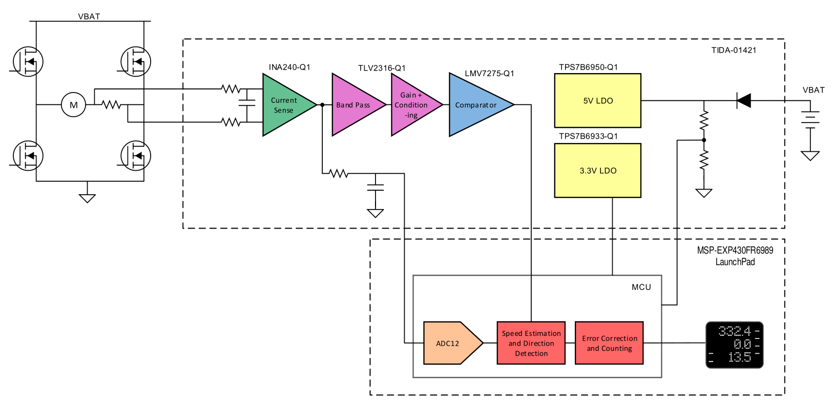
Below is a block diagram provided by TI.
Figure 1 – Ripple Counting Block Diagram, Texas Instruments
The Circuit provided by Texas Instruments also included a very helpful design guide which took some time to wrap our heads around, given our limited exposure to electronic applications up to this point in our education.
The circuit diagram we were working with is shown below
Figure 2 – TI Circuit Diagram
Not shown here are the LDO’s for both a 5 volt and 3.3-volt lines needed to supply power to most of the chips as well as add a bias at certain junctions. This board was designed to work in an automotive environment with voltages ranging from 9 – 18 but the 3Dot board runs a native 3.3 voltage lines from most its chips as well as providing a boost converting to 5 volts if necessary.
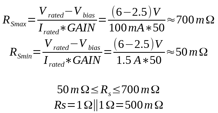
Getting into the operation of this circuit, the first place to start would be the resistor in line with the motor. This Sense Resistor has to be chosen to allow for the largest operating voltage. Based upon the motor we are using we have a stall current of 1.5 A and a no-load current of 100 mA with a max RPM of 220. The current sensing chip chosen has a gain of 50 and is biased via ground and 5-volt reference. The bias places the spikes on the 2.5 voltage DC bias which will be reintroduced at different sections of this analysis. All that allows us to calculate a range for the Resistor we need to use for sensing.
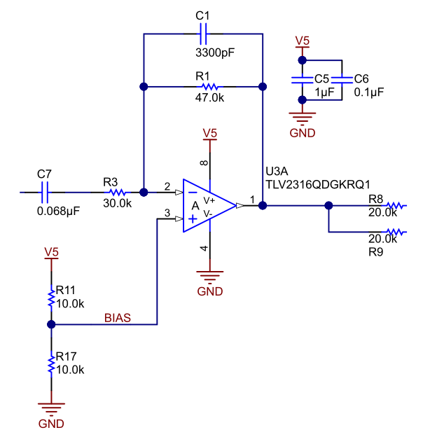
Figure 3 – Band Pass Filter Stage TI
The output from the current sensing stages is then fed into an active inverting band-pass filter.
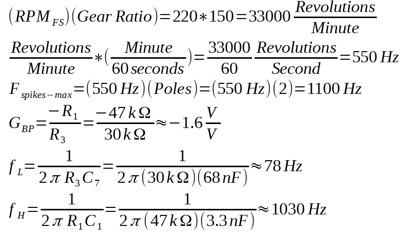
The gain of this stage is determined by the two resistors R1 and R3. The lower cutoff frequency is defined by the C7 and R3 while the upper cutoff is defined by C1 and R1.
The free spin RPM is 220 at the shaft but we have a gear ratio of 150:1 which will mean we have 150 turns of the smaller extended shaft for every one turn of the top. Since the commutation spikes will be caused by the turning of the driving motor we have to take that into consideration when determining output bandwidth. Finally, we have to remember that we are going to have a certain number of spikes depending on the # poles in the motor itself. Taking a magnet on a string we slowly rotated the motor near the magnet to find out how many times it’s attracted and repulsed. It was a crude method but we are pretty certain we’re dealing with a 2 pole permanent magnet motor.
Considering we’re not likely to every reach anything like free spin and that 220 RPM is probably a bit of marketing fluff we can probably stick the same values as used in the TI Circuit.
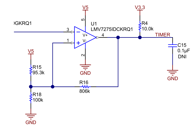
After the Band pass filter comes the differential amplification stage. Both inverting and non-inverting inputs are fed from the same source with the bottom leg being slightly phase shifted by the RC filter. This has the effect of mitigating the fairly large time constant of the high pass section of the previous stage while resulting into a clean channel of spikes that can be used for the comparator stage. The comparator stage is actually working with positive feedback to create a hysteresis loop. That is what lets translate the spikes into a clean transitioning rectangle wave. The thresholds are determined by a formula in the design guide as well.
Figure 4 – TI Comparator Circuit
PCB Design
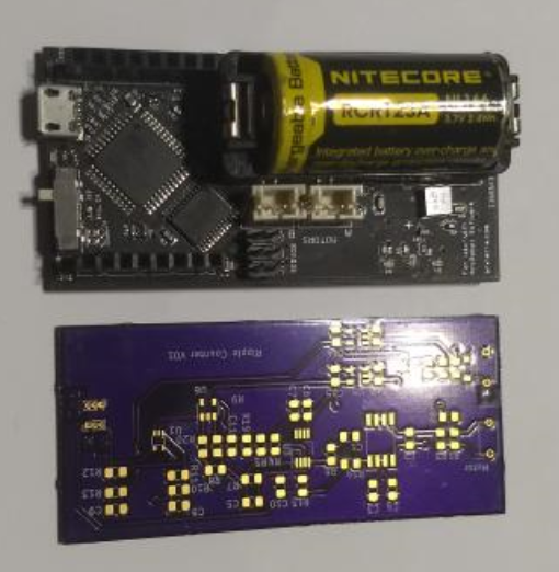
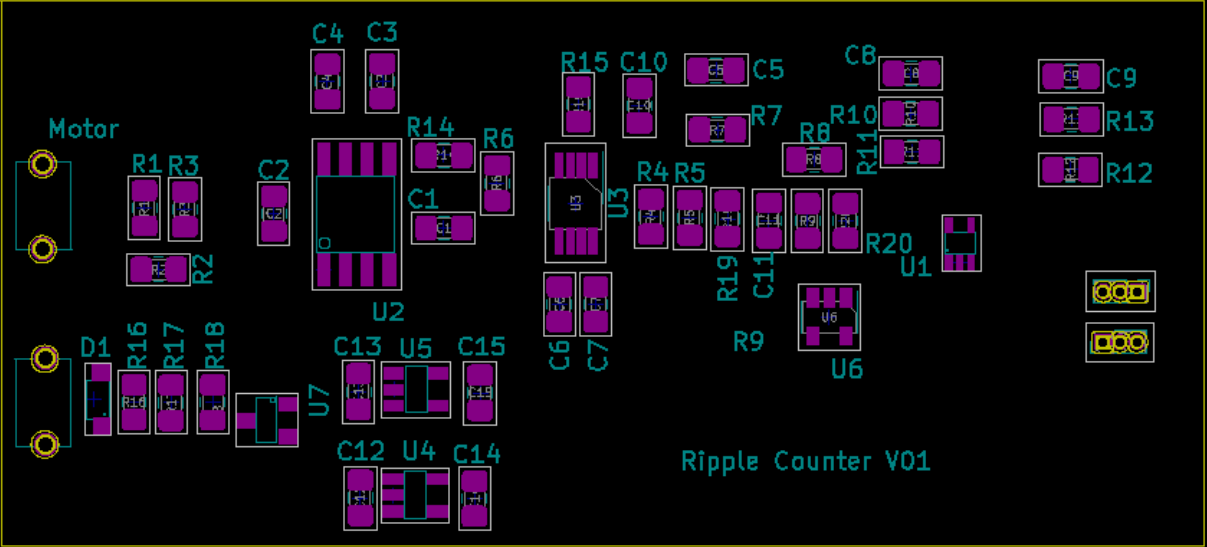
The circuit was an application of the ripple counter shown in the TI application note but the form was set to be similar in size the the 3Dot board. This consideration was so an second edition could be easily adapted from the prototype to the shield. Unfortunately, due to expended shipping times are lost time we were unable to have a fulled tested board working. KICAD was used to make this board.
Figure 5 – PCB & 3Dot size comparison
The board has plenty of room needed for header pins that would be used in the next generation of a stacked ripply board used for sensor-less RPM readings.
Figure 6 – Ripple Counter V01
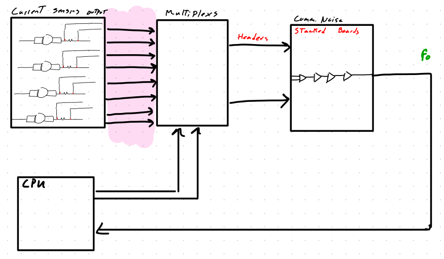
Implementing the circuit in the future could be done by adding a mutliplexer attached to each circuit and sending those signals above to separate board that can be stacked on the motor control board. We then use two signals to control the mutliplexer and the single line to get the frequency coming out of the top board.
Implementation
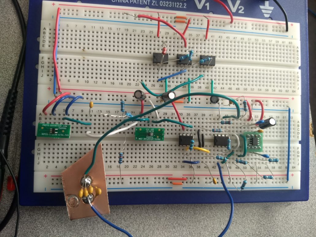
Building this circuit turned out to be more difficult than originally predicted. Originally we had planned to use the PCB we ordered from OSh park but the first time soldering it together was a mess and the voltage regulator we placed on the wrong pads. Regardless of what I tried I couldn’t get the thing de-soldered so we purchased many of the same components.
While building the second circuit, I realized the foot print of the comparator was different from the one i had used on the board and we had to abandon using the PCB.
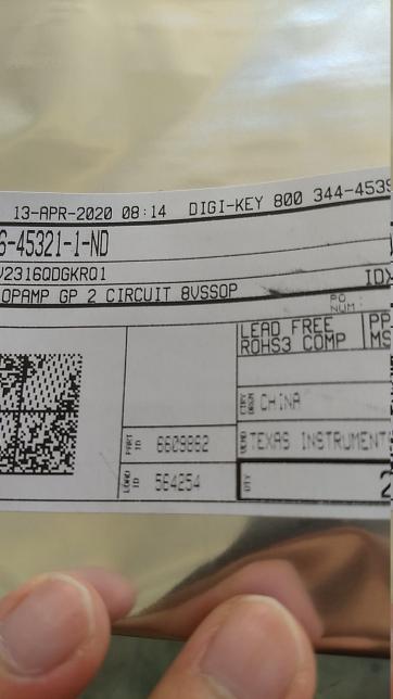
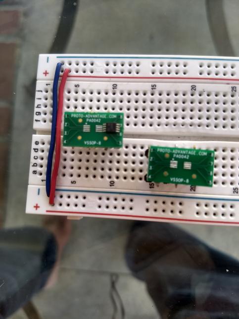
In order to recover from this we purchased some small boards we could use to mount SMD parts on for bread boarding. This was a task in itself to get the parts soldered onto such a small area. I also found that the labeled footprint for the two op-amps was not correct and had to resort to using general purpose uA741 op-amps I had on hand.
Figure 6 – PCB problems
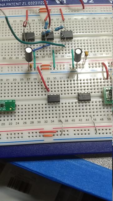
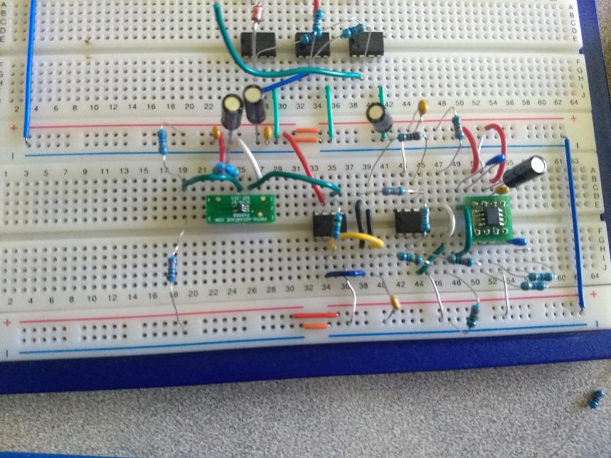
Figure 7 – Bread Boarded Comm Noise Circuit
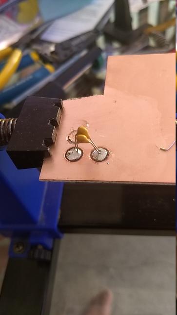
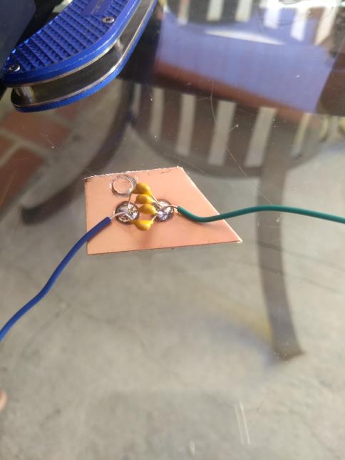
In order to get a 3300 pF cap for the band pass filter I had to do some creative soldering. I got a piece of copper clad board and used a drill press with a hole cutter to make some islands. I was able to solder 3 1000pF caps and a 330pF cap in parallel to get an equivalent capacitor. The one thing to remember is that capacitors in parallel add like resistor in series.
Figure8 – Makeshift Capacitor
In putting this circuit together there was another part that we should pay close attention to. The resistors i had on hand for current sensing are a puny 1/4 W type. My worry is the worst case scenario of close to 6 volts at the motor and pumping 1.5 amps. We’re looking at near 9 Watts of pure circuit crashing, component frying, magic smoke releasing power being hatefully dropped onto my dainty 5 bands. If even 1/36th of that gets spent of my lil’ ol resistors then were looking at melted plastic and broken dreams. It’s advised you get resistors rated far above the nightmare scenario. Of course, these being the times we have, the experiment must proceed and the power supply must be limited.
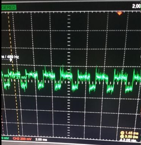
Yet another limitation from a single power supply was the voltage needed to run the chips was different than the voltage needed to run the motor. Since I was using an Arduino to run the experiment anyways, I tried to use the on board 5 volt line to run my chips but once loaded down with the rest of the circuit, the voltage on the rails dropped down to around 3.3. I believe this was the reason most of the circuit was not functioning as cleanly we would have hoped.
Software
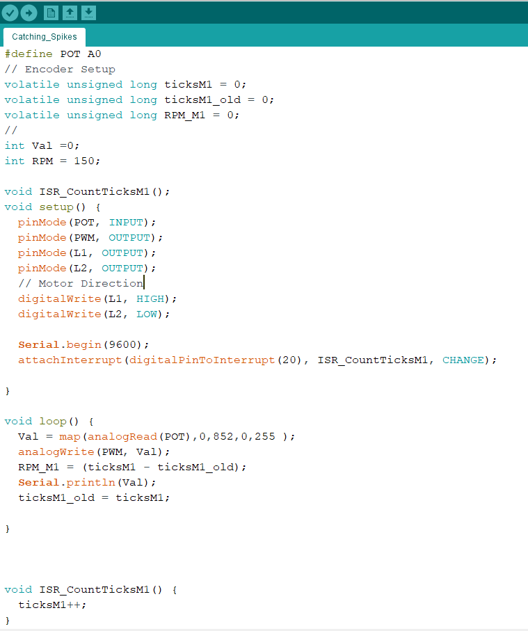
A very simple code was written, mostly to control the L298N used to drive the motor at 6 volts.
Intended Results
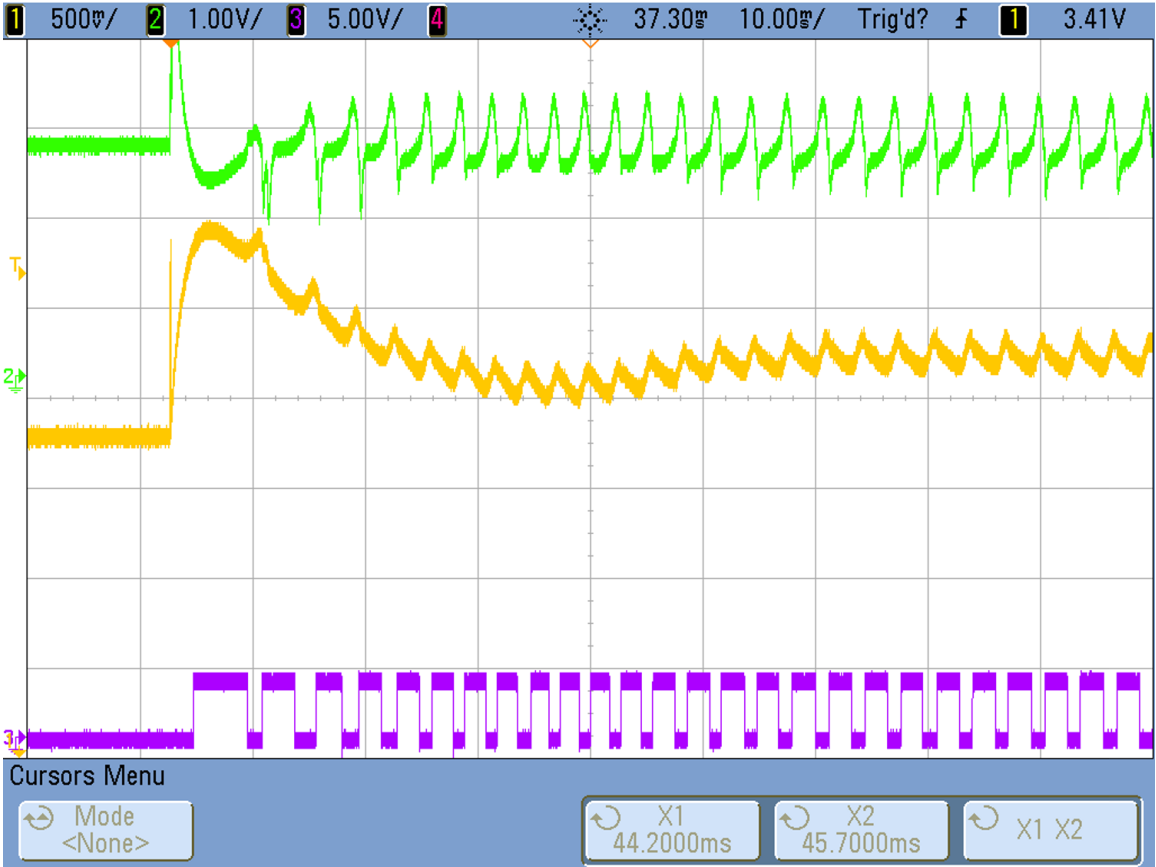
According to the TI design guide we should expect to see a square wave generated at the output whose frequency is a function of the RPM of the motor in test. We can do some sanity check on the circuit by taking measurements are 2 other keys junctions. First we would want to test the output of the band pass filter. This should show us some ripple with a slow drop off between spikes. This large time constant is what we would expect to see introduced by the 3300pF cap of the band-pass stage. That is displayed by the yellow trace on the waveforms provided in the design guide. The next spot to check would be the output of the differential amplifier stage to make sure we have reduced the time constant distortion. This is the green trace of the provided waveform.
Figure 9 – TI Design Guide Scope Outputs
Conclusion
In conclusion, the commutator noise method is a viable way of measuring rpm. The commutator noise is capable of getting readings from the motor going forward and backwards which is an advantage over the back emf method. The commutator noise method was troublesome at first, but we were able to make more progress after finding the texas instruments design guide.
Results
References
- Electronic Design; Bob Pease – What’s all this copper clad stuff, anyhow?
- Electronics Tutorials – Active Band Pass Filter
- Electronics Tutorials – Differential Amplifier
- Electronics Tutorials – Operational Amplifier Comparator
- Electronics Tutorials – Capacitors in parallel and Parallel
- Texas Instruments – Automotive Brushed-Motor Ripple Counter
- Texas Instruments – uA741 Operational Amplifier

