Current Test of the Power HD High Torque Servo 1501 MG
Experiment Conducted by: Matthew Clegg (Controls – Spiderbot), Elaine Doan (Systems Engineering Division), and Kristine Abatay(Project Manager – Spiderbot)
Test Setup written by: Matthew Clegg and Kristine Abatay
Discussion and Results written by: Elaine Doan
A test will be performed in attempt to find the current the Power HD High Torque Servo 1501 MG consumes during operation of the Spiderbot or Biped when 6 volts is applied. From the test, the idle current of the Power HD High Torque Servo 1501 MG will also be identified.
Test Setup
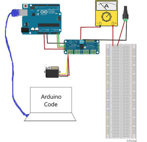
The following setup was used for this test:
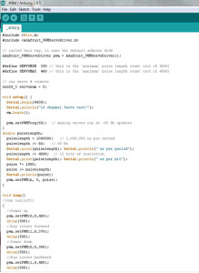
The test was run using breakout boards since they will be used to power the many servo motors in the final construction of Spiderbot. A plastic indicator was attached to the wheel of the servo, which was placed in front of a protractor since the test code used was based off of PWM adjustment as opposed to angle. The following image shows the test code that was used. Matthew Clegg modified the code that was provided by Adafruit (the brand of the breakout board used) to cater to this test:
The final construction of Spiderbot will involve the use of metal brackets to securely connect the servos with the designed components, so a metal bracket was also used in this test. In order to acquire accurate current readings and properly mimic the motion that Spiderbot’s legs will use, small weights were attached to the end of the bracket.
The estimated weight that a single leg servo on Spiderbot will have to support came out to be 437.55 g. This value was acquired using estimates provided by SolidWorks for the designed components and actual weight measurements from a scale for components that we had. The total is comprised of a single femur and tibia component, as well as three servos to account for a single leg, and 1/6 of the chassis design with all of the components it will hold (i.e. Android phone, pan and tilt platform). The total mass that was tested went up to as high as 500 g in order to account for the possibility of undershooting the final mass, keeping in mind the total mass that the servo can handle with the extended arm attached. The following image provides an idea of the approach taken in finding the current for varying lengths of the servo arm:
The first panel of the image shows the metal bracket and the small weights that were attached to it. In order to maintain a constant test mass with a varying arm length, the weights were first placed on the inner and outer portions of the bracket without exceeding the initial length of the arm, as depicted in the second panel of the image. Finally, the masses were stacked on the bracket to extend the length of the arm, as shown in third panel, and more current measurements were obtained.
The current read through the multimeter varied constantly throughout the test, so the values that were recorded were the largest values that appeared consistently on the multimeter for each angle value. A quick video depicting the setup of this servo test can be found in the link below:
Discussion and Results
When working with servos, there are two currents worth noting: the idle current and the stall current. The idle current is the current consumed by the servo when it is not performing but connected to the power source. It is important to identify the idle current because it will provide users with the upper bound on how long a battery powered application can run. The stall current is the maximum current drawn by the servo when it is performing. The stall current will provide users with the minimum current requirement for the power supply. The actual current a servo consumes during operation will vary between the idle current and stall current. Servo currents usually are not specified by the manufacturer and the user is required to run tests to find the idle current and stall current. It’s easy to measure the idle current since it is low, constant, and only requires a simple connection to a power supply. A standard servo such as the Power HD High Torque Servo 1501 MG will have an idle current around 0.01 -0.03 amps depending on the power supply. Stall currents are more difficult to measure because stalling a servo can result in a damaged servo. A standard servo such as the Power HD High Torque Servo 1501 MG will have a stall current around 1 amp (finding the stall current of the Power HD High Torque Servo 1501 MG will not be attempted in this test. Finding the current a servo draws during normal operation of the Spiderbot and Biped will be attempted instead). The current will be approximately linear with the supply voltage, so the currents drawn at 7 V will be almost double those at 4 V. Adjusting the rotational degrees of the servo will typically draw more current linearly. Increasing the torque by ten times will typically draw ten times the current.
Part A
IDLE CURRENT
Idle Current at 6.0 V = 0.03 amps
Part B
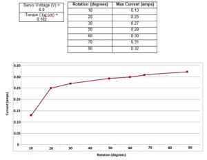
SHAFT ROTATION VS CURRENT
The graph shows how the current draw is affected by the increasing rotation of the servo’s shaft from 10 to 90 degrees. The current drawn increases steadily by approximately 10 mA as the rotation degrees increase by increments of 10 degrees.
Part C
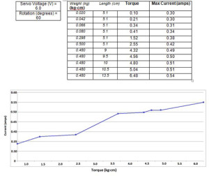
TORQUE VS CURRENT
The graph shows how the current draw is affected by the increasing torque from 0.10 to 6.48 kg•cm. The current drawn increases by approximately 40 mA as the torque increase by increments of 1 (kg•cm).


