Custom Chassis PCB
Author: Diane Kim (Division Manager of E&C Hardware)
Verified By: Jordan Smallwood (Project Manager)
Approved By: Miguel Garcia (Quality Assurance)
Table of Contents
Introduction
Unlike many of the other projects that are required to use the 3DoT board, we will be using the ATMega 2560 due to a large amount of connections. Since many of the interconnections are from pin to pin, specifically the motor drivers, we have made a custom shield to route many of these signals.
Aside from the connections to the peripheral devices that are mentioned above, the custom PCB for the chassis has the buck converter that will convert the 12v from the battery to 5v to supply power to the ATmega2560.
Design of the PCB
Buck Converter
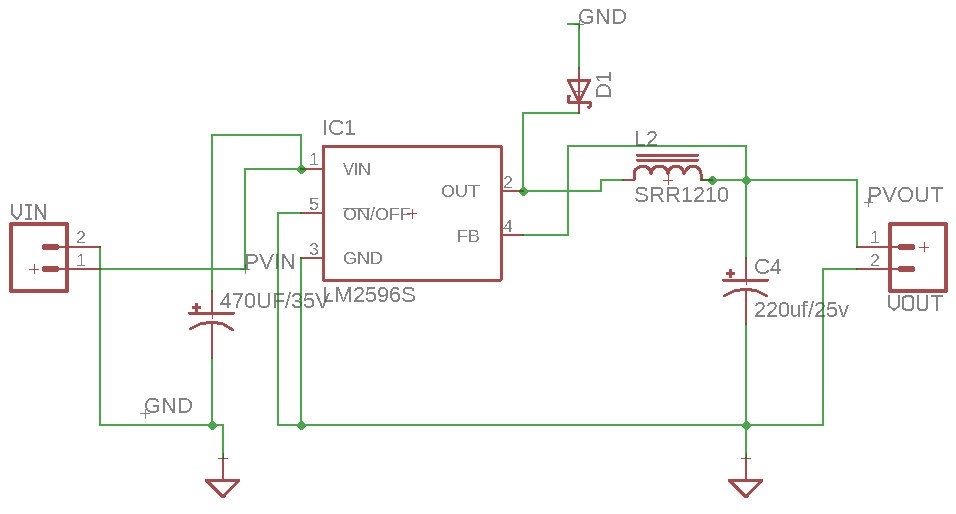
Through a different experiment, we confirmed that we will be using the LM2596 buck converter. Since we will be converting between a fixed voltage of 12v to 5v, we are using the fixed output design from the datasheet.
Based on the datasheet, the Cin , Cout, and inductor value was determined. The capacitors also have to be low-ESR or impedance for the circuit. The traces that are drawn with bolded lines must be kept short and thick for better results.
- Cin: 470uF/35v
- Cout: 220uF/25v
- Inductor: 68uH/3.10A
Connection for the Motor Driver
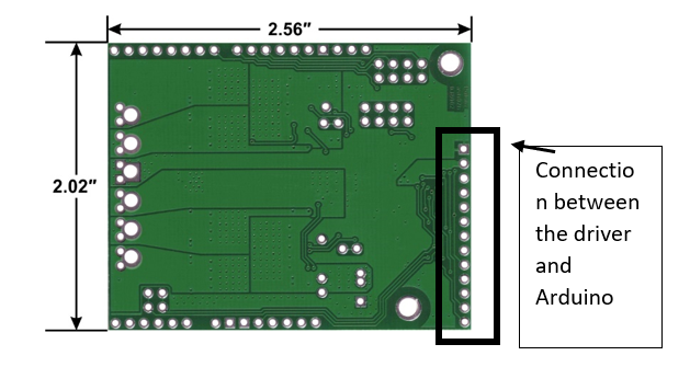
We are using the Pololu dual VNH5019 motor driver for the Pathfinder. Since we are limited to a 5×4 cm (WxL) board, due to limitation’s of the PCB fabrication machine we are using, we have decided to place the connectors so that the board doesn’t exceed the maximum size. The drivers are placed vertically so that the width of the PCB doesn’t exceed 5 cm.
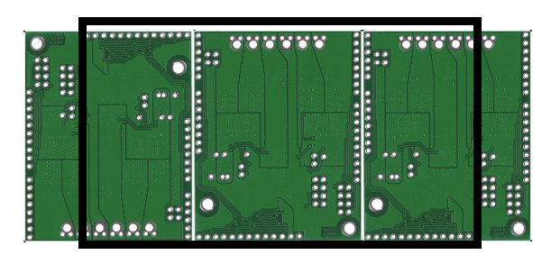
Figure 4: The Overview of how the motor drivers are placed The black outline is the line of dimension of the shield so that it doesn’t exceed 5 cm.
Connection’s of the other peripheral systems
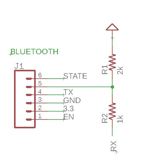
We initially thought about making the HM-10 Bluetooth module a part of our PCB circuit, but we instead decided to use the breakout board and use connectors. Since the RX of the Arduino can only take in 3.3v and the TX of the HM-10 outputs 5v a voltage divider was used. To get 3.3v from 5v, we used 1k and 2k resistors.
- The current sensors are used to measure the amount of current from the motors. Although there are current sensors in the motors, the lower limit of the amount of
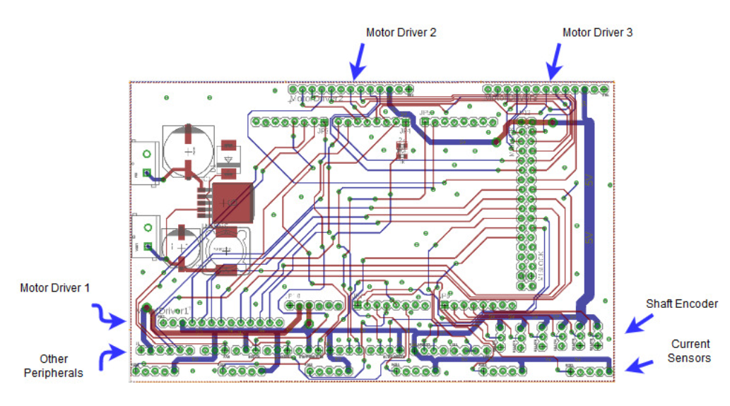
current is not low enough for our no-load protocol. Therefore these current sensors will be connected to the motor drivers and the motor’s pin for the current will be routed through these current sensors. We used the Adafruit INA169 DC current sensor breakout board. - Other peripheral devices are the ones mentioned above: motor drivers (3), shaft encoders for the motors (6), ultrasonic sensors (2), servo motors (2), LEDs (2), fan, HM-10 (Bluetooth), current sensors (6), and stepper motor drivers (3). The connection is based on the interface matrix. The connectors are placed on the outer part of the shield so that the motor drivers do not cover the connections.
Final Version of PCB
Figure 6: Eagle File for Final Chassis PCB with ground pour
Figure 7: Final Chassis PCB without Ground Pour
The board was very simple to design since it essentially connected all the systems together, however, there were some considerations that needed to be accounted for. The size of the board was restricted to 4″ by 5″ due to the fabrication machine used. Since the motor drivers had to be placed horizontally and the board was a shield for the ATmega2560, the positions of the connectors were fixed and some of the traces had more resistance than the shorter wires. In addition, the ground and the power
planes needed to be laid out so that there is a good connection. This means that ground vias were added and the trace for the power was thicker than the traces for transmitting data. Another problem that arose was the connection between the pads and the connectors. The connectors did have a connection but it was easily disconnected if a small force was applied to it.
References
- EAGLE File: https://drive.google.com/open?id=1-hPQAabUNwHn-SUBNcfJ6V6lTwZHwjUo under MotorDriverShield_aaproved.brd and .sch
- Buck Converter: http://www.ti.com/product/LM2596
- Motor Driver: https://www.pololu.com/product/2502


