Custom PCB for Solar Panels
Author: Diane Kim (Division Manager of E&C Hardware)
Verified By: Jordan Smallwood (Project Manager)
Approved By: Miguel Garcia (Quality Assurance)
Table of Contents
Introduction
The second PCB is for the solar panels which consists of the connection for the stepper motor drivers (3), current sensors (6), and GPIO expander. We are using the stepper motor from Sparkfun therefore we decided to go with the stepper motor driver associated with it—the EasyDriver. Although we wanted to implement the circuit itself, the IC that is used for the EasyDriver was not available, therefore we are going with the shield. To decrease the pins from the EasyDriver to the ATmega2560, we are using the I2C bus for the EasyDriver and the current sensors.
Stepper Motor Driver Connection
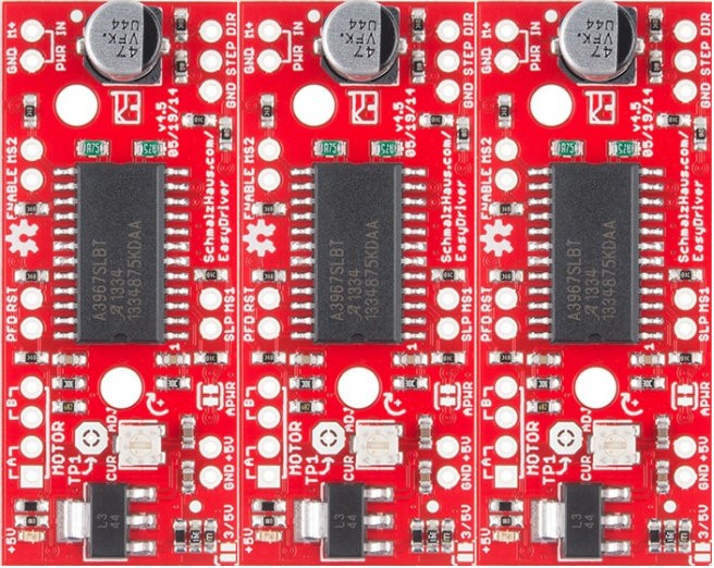
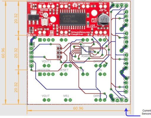
The connection from the EasyDriver to the ATmeag2560 are the MS1, MS2, DIR, ENABLE, and STEP. The Eagle file for the EasyDriver schematic can be found on Sparkfun’s website. The 3 stepper motor drivers are placed side-by-side horizontally.
Figure 1: Placement of the Stepper Motor Driver
Figure 2: Placement of Motor Drivers on Solar PCB
- MS1 and MS2
MS stands for micro-step and is used to determine the resolution of the step. For our specific design, we will be setting both MS1 and MS2 to ground or both to low since we don’t need high resolution to fold and unfold the solar panels.
Figure 3: Truth Table of MS1 and MS2 Resolution
- DIR & ENABLE
The DIR pin is a logic input that determines the direction of the stepper motor. The ENABLE pin is a logic input that determines whether the IC drives the motor. These two inputs will connect with the Atmega2560 by the I2C bus.
- STEP
STEP is a logic input that is triggered when the pin goes from high to low. The STEP is connected between all three motor drivers since they will all be operating at the same time.
I2C Bus
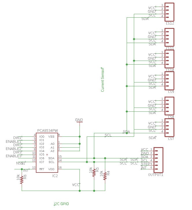
I2C connection uses the two connections SDA and SCL to connect between the master and the slaves. If we didn’t go with the I2C connection, we would have needed 7 wires from the stepper motor driver to the ATmeaga2560. By using the GPIO expander, we connect DIR and ENABLE for all 3 stepper motor driver to SCL and SDA. For our circuit, we are using the TCA9534APWR chip from Texas Instruments. Each I2C bus needs a pull-up resistor for both SDA and SCL. In addition to the SDA and SCL from the GPIO expander, we are adding the SDA and SCL from the current sensors to the I2C bus. We are using the 1NA3221 Breakout Board from Switch Doc which has four programmable addresses.
Figure 4: I2C Bus connection of Stepper Motor (DIR and ENABLE) and Current Sensors)
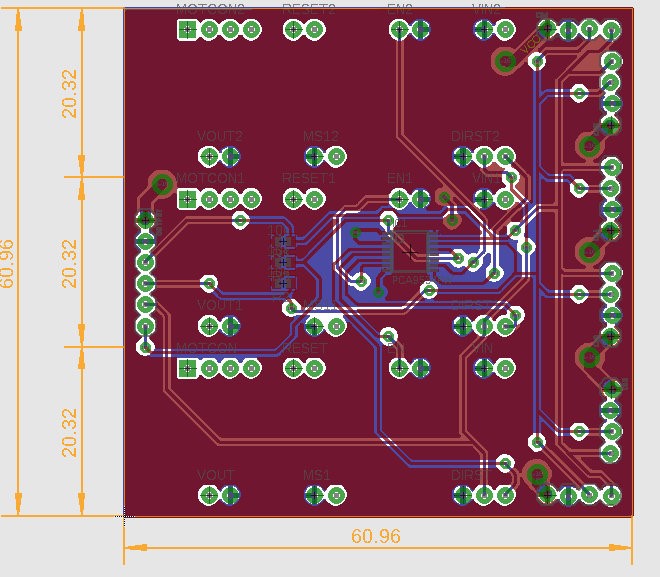
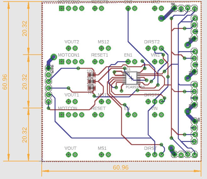
Final Version of the PCB
Figure 5: Final Version of PCB with Copper Ground and Power Planes
Figure 6: Final Version of PCB without Copper Ground and Power Planes
Conclusion:
The Solar Panel PCB was never tested due to the solar panel mechanism never being completed.
References
- Eagle File: https://drive.google.com/open?id=1-hPQAabUNwHn-SUBNcfJ6V6lTwZHwjUo under SolarPanelShield.brd and .sch
- I2C Bus: https://learn.sparkfun.com/tutorials/i2c
- Stepper Driver: https://www.sparkfun.com/products/12779

